DCS BGRU3030 BK INSTL BACKGUARD SV-B DCS US
- Taper
- BK INSTL BACKGUARD SV-B DCS US

US CA
Installation instructions
Backguard for professional
ranges and cooktops
Models BGRU, BGRU2 and BGCU
Modèles BGRU, BGRU2 et BGCU
Guide d’installation
Dosseret pour cuisinières et
tables de cuisson professionnelles


1
US
CA
WARNING!
Improper installation, adjustment, alteration, service or maintenance can cause property damage, injury or death.
Read the installation, operating and maintenance instructions thoroughly before installing, using or servicing this
equipment.
WARNING!
If the information in this manual is not followed exactly, a fire or explosion may result causing property damage,
personal injury or death.
Do not store or use gasoline or other flammable vapors and liquids in the vicinity of this or any other appliance.
DANGER
If You Smell Gas:
1. Do not try to light any appliance.
2. Do not touch any electrical switch; do not use any phone in your building.
3. Immediately call your gas supplier from a neighbor’s phone. Follow the gas supplier’s instructions.
4. If you cannot reach your gas supplier, call the fire department.
5. Installation and service must be performed by a qualified installer, service agency or the gas supplier.
WARNING!
To reduce the risk of injury to persons in the event of a cooktop grease fire, observe the following: Turn burner off
first. Smother flames with a close-fitting lid, cookie sheet, metal tray, baking soda or use a dry chemical or foam-type
fire extinguisher. Be careful to prevent burns. If the flames do not go out immediately evacuate and call the fire de-
partment. Never pick up a flaming pan - You may be burned. DO NOT USE WATER ON GREASE FIRES, including wet
dishcloths or towels - a violent steam explosion will result. Use an extinguisher ONLY if:
1. You know you have a Class ABC extinguisher, and you already know how to operate it.
2. The fire is small and contained in the area where it started.
3. The fire department is being called.
4. You can fight the fire with your back to an exit.
WARNING!
Do not place items of interest to children on racks or appliance. Children could be seriously injured if they should
climb onto or into the appliance to reach these items.
WARNING!
Do not place combustible material (paper, cloth, plastic, etc.) on the rack.
PLEASE RETAIN THIS MANUAL FOR FUTURE REFERENCE.
A MESSAGE TO OUR CUSTOMERS
Thank you for selecting this Backguard System. Because of the unique features of this accessory we have
developed this Installation Guide. It contains valuable information on how to install your new Backguard System.
Keep this guide handy, as it will help answer questions that may arise as you use your new accessory.
For your convenience, product questions can be answered by a DCS Customer Care Representative by phone:
1-888-
936-7872
, or email:
.
NOTE: Inspect the product to verify that there is no shipping damage. If any damage is detected, call the shipper
and initiate a damage claim. DCS by Fisher & Paykel is not responsible for shipping damage.
DO NOT discard any packing material (box, pallet, straps) until the unit has been inspected.

2
US
CA

3
US
CA
TABLE OF CONTENTS
Backguards for ranges – BGRU & BGRU2 models
SPECIFICATIONS 4
RANGE MOUNT STANDARD BACKGUARD INSTALLATION 4
WALL MOUNT FULL BACKGUARD INSTALLATION 5
Backguards for cooktops – BGCU models
SPECIFICATIONS 8
WALL MOUNT STANDARD BACKGUARD INSTALLATION 8
WALL MOUNT FULL BACKGUARD INSTALLATION 9

4
US
CA
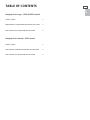
SPECIFICATIONS
RANGE MOUNT STANDARD BACKGUARD
INSTALLATION
1. Unpack the backguard and screw the front section onto the back section, as shown (Fig. 01)
2. Align the backguard with the range, so that it rests on the island trim. Fasten the bottom of the backguard to the
rear of the range using all the screws provided, as shown (Fig. 02). The two center screws come already attached
to the range for your convenience.
Fig.01
Fig.02
A
8-3/4 "
26-1/2 "
11-13/32 "
12 "
A
13/16 "
1-5/16 "
# 8
Self-tapping
sheet metal
screws
Back Section
Screw is loosened
Front Section
BACKGUARDS FOR RANGES - BGRU2 MODELS
WALL MOUNT FULL BACKGUARDS
MODEL A RACK (13-5/8”) QTY. RACK (16-5/8”) QTY.
BGRU-3030 29-7/8” 2 -
BGRU-3036 35-7/8” - 2
BGRU-3048 47-7/8” 2 1
RANGE MOUNT STANDARD BACKGUARDS
MODEL A
BGRU2-1530 29-7/8”
BGRU2-1536 35-7/8”
BGRU2-1548 47-7/8”

5
US
CA
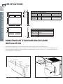
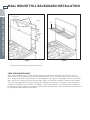
WALL MOUNT FULL BACKGUARD INSTALLATION
RECOMMENDED INSTALLATION ORDER:
1) VENT HOOD 2)BACKGUARD SYSTEM 3) RANGE
1. Locate and level range per installation instructions.
2. After unpacking all backguard system parts, locate the Back Section 1/4” (see fig. 03) above and centered over
the Island Trim attached to the range.* Secure Back Section to wall with the appropriate fasteners (not supplied)
to anchors or wood stud (fig. 03).
WARNING:
The Back Section must be securely fastened to the wall. Failure to do so could cause damage or personal injury if
the Backguard was to pull free from wall when racks are loaded. The maximum weight placed on each rack should
be 10 lbs.
*After 1/4” is located, slots in back section may be used to adjust spacing between range island trim and
backguard for a flush fit.
3. Attach rod, end caps and center stanchion to Front Section of backguard with #10 machine screws supplied
(fig. 04).
4. Bend wedge-shaped tabs down on top of the front section approximately 3/16”. When mounting the front
section, insure that these tabs engage the mating holes in the top of the rear section (see fig. 05, page 4).
5. Secure Front Section of backguard to Back Section with #8 self-tapping sheet metal screws supplied
(fig. 05, page 4).
6. Attach racks to rod (fig. 06, page 4). The maximum weight placed on each rack should be 10 lbs.
Fig.03
Fig.04
#10
Machine
Screws
Back Section
Island
Trim
Front Section
End
Cap
End
Cap
Center
Stanchion
Rod
Slots to choose
desired spacing
between Range Island
Trim and Backguard.
Bend down approx. 3/16”
1/4”
BACKGUARDS FOR RANGES - BGRU2 MODELS
16” for 30” Range
32” for 36/48” Range

6
US
CA
WALL MOUNT FULL BACKGUARD INSTALLATION
Fig.05 Fig.06
#8
Self-
tapping
sheet
metal
screws
Back Section
Front Section
Rack
Holes*
Tabs*
*Insure tabs and holes engage to secure top of backguard.
CARE AND MAINTENANCE
This is made of stainless steel. Use the mildest cleaning procedure first. Hot soapy water, rinse and dry. If
the panel has food soil remaining, try a general kitchen cleaner, such as Fantastik®, Simple Green® or Formula
409®. Apply cleaner with a damp sponge, rinse thoroughly and dry. Always scrub lightly in the direction of the
grain. Do not use a steel wool pad, it will scratch the surface. To touch up noticeable scratches in the stainless
steel, sand very lightly with dry 100 grit emery paper, rubbing in the direction of the grain. After cleaning use
a stainless steel polish, such as Stainless Steel Magic®. If the rear top burners are used extensively on high it is
possible for the vertical stainless steel panel to discolor from the burner heat. This discoloration can be removed
by using Revere Ware Stainless Steel Cleaner.
BACKGUARDS FOR RANGES - BGRU2 MODELS

7
US
CA
NOTES

8
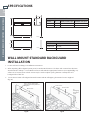
# 8
Self-tapping
sheet metal
screws
Back Section
Back Section
Front Section
Trim
Slots to choose desired spac-
ing between Cooktop Trim and
Backguard.
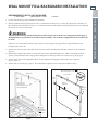
Fig.07 Fig.08
32”
US
CA
SPECIFICATIONS
WALL MOUNT STANDARD BACKGUARD
INSTALLATION
1. Locate and level cooktop per installation instructions.
2. After unpacking all backguard system parts, locate the Back Section 1/4” above and centered over the Trim
attached to the cooktop.* Secure Back Section to wall with the appropriate fasteners (not supplied)(fig. 07).
*After 1/4” is located, slots in back section may be used to adjust spacing between cooktop trim and
backguard for a flush fit.
3. Secure Front Section of backguard to Back Section with #8 self-tapping sheet metal screws supplied
(fig. 08).
A
8-3/4 "
30 "
12 "
A
13/16 "
1-5/16 "
11-13/32 "
1/4”
BACKGUARDS FOR COOKTOPS - BGCU MODELS
WALL MOUNT FULL BACKGUARDS
MODEL A RACK (13-5/8”) QTY. RACK (16-5/8”) QTY.
BGCU-3036 35-7/8” - 2
BGCU-3048 47-7/8” 2 1
WALL MOUNT STANDARD BACKGUARDS
MODEL A
BGCU-1236 35-7/8”
BGCU-1248 47-7/8”

9
US
CA
1/4”
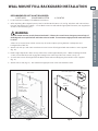
WALL MOUNT FULL BACKGUARD INSTALLATION
RECOMMENDED INSTALLATION ORDER:
1) VENT HOOD 2) BACKGUARD SYSTEM 3) COOKTOP
1. Locate and level cooktop per installation instructions.
2. After unpacking all backguard system parts, locate the Back Section 1/4” (see fig. 09) above and centered over
the Trim attached to the cooktop.* Secure Back Section to wall with the appropriate fasteners (not supplied) to
anchors or wood stud (fig. 09).
WARNING:
The Back Section must be securely fastened to the wall. Failure to do so could cause damage or personal injury if
the Backguard was to pull free from wall when racks are loaded. The maximum weight placed on each rack should
be 10 lbs.
*After 1/4” is located, slots in back section may be used to adjust spacing between cooktop trim and
backguard for a flush fit.
3. Attach rod, end caps and center stanchion to Front Section of backguard with #10 machine screws supplied
(fig. 10).
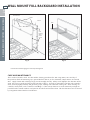
4. Bend wedge-shaped tabs down on top of the front section approximately 3/16”. When mounting the front
section, insure that these tabs engage the mating holes in the top of the rear section (see fig. 11).
5. Secure Front Section of backguard to the Back Section with #8 self-tapping sheet metal screws supplied
(fig. 11).
6. Attach racks to rod (fig. 12). The maximum weight placed on each rack should be 10 lbs.
#10
Machine
Screws
Back Section
Trim
Front Section
End
Cap
End
Cap
Center
Stanchion
Rod
Slots to choose
desired
spacing between
Cooktop Trim
and Backguard.
Bend down approx. 3/16”
Fig.09 Fig.10
32”
BACKGUARDS FOR COOKTOPS - BGCU MODELS

10
US
CA
WALL MOUNT FULL BACKGUARD INSTALLATION
Back Section
Front Section
Rack
Holes*
Tabs*
*Insure tabs and holes engage to secure top of backguard.
Fig.11 Fig.12
CARE AND MAINTENANCE
This is made of stainless steel. Use the mildest cleaning procedure first. Hot soapy water, rinse and dry. If
the panel has food soil remaining, try a general kitchen cleaner, such as Fantastik®, Simple Green® or Formula
409®. Apply cleaner with a damp sponge, rinse thoroughly and dry. Always scrub lightly in the direction of the
grain. Do not use a steel wool pad, it will scratch the surface. To touch up noticeable scratches in the stainless
steel, sand very lightly with dry 100 grit emery paper, rubbing in the direction of the grain. After cleaning use
a stainless steel polish, such as Stainless Steel Magic®. If the rear top burners are used extensively on high it is
possible for the vertical stainless steel panel to discolor from the burner heat. This discoloration can be removed
by using Revere Ware Stainless Steel Cleaner.
#8
Self-
tapping
sheet
metal
screws
BACKGUARDS FOR COOKTOPS - BGCU MODELS

11
US
CA
NOTES

12
US
CA
FR

13
US
CA
FR
AVERTISSEMENT!
Toute installation, ajustement, altération, maintenance ou entretien incorrect peut causer des dommages matériels,
des blessures ou la mort. Veuillez lire soigneusement ces instructions d’installation, d’utilisation et d’entretien
avant d’installer, utiliser ou effectuer l’entretien de cet appareil.
AVERTISSEMENT!
Si les informations de ce manuel ne sont pas suivies à la lettre, un incendie ou une explosion peuvent se produire
et causer des dommages matériels, des blessures ou la mort.
Évitez de stocker ou d’utiliser de l’essence ou tout autre liquide et vapeur inflammable à proximité de cet appareil
ou de tout autre.
POUR VOTRE SÉCURITÉ
Si vous sentez une odeur de gaz :
1. N’essayez pas d’allumer aucun appareil électroménager.
2. Ne touchez aucun interrupteur électrique; n’utilisez aucun téléphone dans l’édifice.
3. Appelez immédiatement votre fournisseur de gaz de chez un voisin. Suivez les instructions du fournisseur de gaz.
4. Si vous n’arrivez pas à joindre votre fournisseur de gaz, appelez les pompiers.
5. Toute installation ou service doit être confié à un installateur qualifié, un organisme de service ou le fournisseur de gaz.
AVERTISSEMENT!
Pour réduire les risques de blessures en cas de feu de graisse sur la table de cuisson, respectez les consignes suivantes: Éteignez
d’abord le brûleur. Étouffez les flammes à l’aide d’un couvercle hermétique, d’une plaque à biscuits, d’un plateau métallique,
avec du bicarbonate de soude ou à l’aide d’un extincteur à poudre ou à mousse. Attention à ne pas vous brûler. Si les flammes ne
s’éteignent pas immédiatement, évacuez les lieux et appelez les pompiers. Ne prenez jamais en main une poêle ou une casserole
qui a pris feu, vous pourriez vous brûler. N’UTILISEZ PAS D’EAU SUR LES FEUX DE GRAISSE, y compris des serviettes mouillées;
une explosion de vapeur violente pourrait en résulter. Utilisez un extincteur SEULEMENT si :
1. Vous êtes sûr qu’il s’agit d’un extincteur de classe ABC et savez comment le faire fonctionner.
2. Le feu est limité et restreint à la zone où il s’est déclenché.
3. Le service des pompiers a été appelé.
4. Vous pouvez combattre l’incendie le dos tourné vers une sortie.
AVERTISSEMENT!
Évitez de ranger sur les grilles ou l’appareil des objets pouvant attirer les enfants. Ceux-ci peuvent se blesser
sérieusement s’ils grimpent sur ou dans l’appareil pour atteindre les objets en question.
AVERTISSEMENT!
Évitez de placer des matériaux combustibles (papier, tissu, plastique, etc.) sur la grille.
À L’INTENTION DE NOS CLIENTS
Nous vous remercions d’avoir choisi ce dosseret. Nous avons conçu ce Manuel d’installation pour expliquer ses
fonctions uniques. Il contient des informations extrêmement utiles sur la façon d’installer correctement votre
nouveau dosseret. Gardez ce manuel à portée de main afin de rapidement trouver réponse à vos questions
durant l’utilisation de votre nouvel accessoire.
Si vous avez des questions au sujet de notre produit, communiquez avec un représentant du centre de service à
la clientèle DCS par téléphone : 1-888-
936-7872
, ou par courriel :
.
REMARQUE : Inspecter le produit pour vérifier qu’il n’a pas été endommagé pendant l’expédition. En cas de
dommages, contacter le transporteur et entamer une déclaration pour dommage. DCS by Fisher & Paykel n’est
en aucun cas responsable des dommages pendant l’expédition.
Ne pas jeter le matériau d’emballage (boîte, palette, sangles) avant d’avoir inspecté l’unité.
VEUILLEZ CONSERVER CE MANUEL À TITRE DE RÉFÉRENCE.

14
US
CA
FR
TABLE DES MATIÈRES
Dosserets pour cuisinières – modèles BGRU2
SPÉCIFICATIONS 15
INSTALLATION DU DOSSERET ORDINAIRE 15
INSTALLATION DU DOSSERET MURAL INTÉGRAL 16
Dosserets pour tables de cuisson – modèles BGCU
SPÉCIFICATIONS 19
INSTALLATION DU DOSSERET MURAL ORDINAIRE 19
INSTALLATION DU DOSSERET MURAL INTÉGRAL 20

15
US
CA
FR
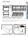
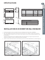
SPÉCIFICATIONS
INSTALLATION DU DOSSERET ORDINAIRE
1. Déballez le dosseret et vissez la section avant sur la section arrière, comme illustré (Fig.01).
2. Alignez le dosseret sur l’arrière de la cuisinière de façon à ce qu’il repose sur la garniture d’îlot, puis fixez. Fixez le dosseret sur
l’arrière de la cusinière avec tous les vis fournies, comme illustré (Fig. 02).
Fig.02
Fig.01
A
22,23 cm
(8-3/4 po)
30,5 cm
(12 po)
67,3 cm
(26-1/2 po)
29 cm
(11-13/32 po)
A
3,33 cm
(1-5/16 po)
2 cm
(13/16 po)
DOSSERETS POUR CUISINIÈRES– MODÈLES BGRU2
DOSSERET MURAL INTÉGRAL
MODÉLE A GRILLES
(34,6cm)
(13-5/8 po)
QTÉ.
GRILLES
(42,2cm)
(16-5/8 po)
QTÉ.
BGRU-3030 75,9cm (29-7/8 po) 2 -
BGRU-3036 91,1cm (35-7/8 po) - 2
BGRU-3048 121,6cm (47-7/8 po) 2 1
DOSSERET ORDINAIRE
MODÉLE A
BGRU2-1530 75,9cm (29-7/8 po)
BGRU2-1536 91,1cm (35-7/8 po)
BGRU2-1548 121,6cm (47-7/8 po)
Section avant
Section arrière
Vis à tôle
autotarau-
deuses n° 8
Vis desserrée

16
US
CA
FR
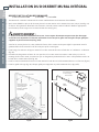
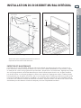
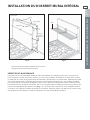
INSTALLATION DU DOSSERET MURAL INTÉGRAL
ORDRE D’INSTALLATION RECOMMANDÉ :
1) HOTTE À ÉVACUATION 2) DOSSERET 3) CUISINIÈRE
1. Positionnez la cuisinière et mettez-la de niveau conformément aux instructions d’installation.
2. Après avoir déballé les pièces du dosseret, placez la section arrière en la centrant à 6,5 mm (1/4 po) (voir fig. 03)
au-dessus de la garniture d’îlot fixée à la cuisinière.* Fixez la section arrière à l’aide des fixations appropriées
(non fournies) aux ancrages ou à l’ossature de bois du mur (fig. 03).
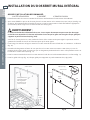
AVERTISSEMENT :
La section arrière doit être solidement fixée au mur. Le non respect de cette mesure peut causer des dommages
ou des blessures corporelles si le dosseret se décroche du mur lorsque les grilles sont chargées. Chaque grille peut
supporter un poids maximum de 4,5 kg (10 lb).
*Une fois la section placée à 6,5 mm, utilisez les fentes de la section arrière pour régler l’espacement entre la
garniture d’îlot de la cuisinière et le dosseret pour qu’ils soient égaux.
3. Fixez la tige, les embouts et l’appui central à la section avant du dosseret à l’aide des vis à métaux n° 10 fournies
(fig. 04).
4. Recourbez les languettes en forme de coin par-dessus la section avant sur environ 5 mm (3/16 po). Lors du
montage de la section avant, assurez-vous que ces languettes pénètrent dans les trous correspondants situés sur
le haut de la section arrière (voir fig. 05).
5. Fixez la section avant du dosseret à la section arrière à l’aide des vis à tôle autotaraudeuses n° 8 fournies (fig. 05).
6. Fixez les grilles à la tige (fig. 06). Chaque grille peut supporter un poids maximum de 4,5 kg (10 lb).
Fig.03 Fig.04
Vis à
métaux
n° 10
Section arrière
Garniture
d’îlot
Section avant
Embout
Embout
Appui
central
Tige
Fentes pour choisir
l’espacement voulu
entre la garniture
d’îlot de la cuisinière
et le dosseret.
Recourbez sur environ
5 mm (3/16 po).
DOSSERETS POUR CUISINIÈRES– MODÈLES BGRU2
40 cm pour cuisinières de 76 cm
(16 po pour cuisinières de 30 po)
91 cm pour cuisinières de 91/122 cm
(36 po pour cuisinières de 36/48 po)
6,5 mm
(1/4 po)

17
US
CA
FR
INSTALLATION DU DOSSERET MURAL INTÉGRAL
Fig.05 Fig.06
Vis à tôle
autota-
raudeuses
n° 8
Section arrière
Section avant
Grille
Languettes*
Trous*
*Assurez-vous que les languettes pénètrent dans les trous cor-
respondants de sorte à fixer le haut du dosseret.
ENTRETIEN ET MAINTENANCE
Ce produit est en acier inoxydable. Employez d’abord la méthode de nettoyage la plus douce. Lavez avec de
l’eau savonneuse chaude, rincez puis séchez. S’il y a encore des souillures alimentaires sur le panneau, essayez
un nettoyant de cuisine d’usage général tel que Fantastik®, Simple Green® ou Formula 409®. Appliquez le produit
avec une éponge humide, rincez abondamment puis séchez. Frottez toujours dans le sens du grain. N’utilisez
pas de laine d’acier car cela peut égratigner la surface. Pour réparer des égratignures visibles à l’œil nu, frottez
très légèrement avec du papier de verre fin, dans le sens du grain. Après le nettoyage, utilisez un produit à polir
pour acier inoxydable tel que Stainless Steel Magic®. Il est possible que le panneau en acier inoxydable vertical
se décolore sous l’effet de la chaleur du brûleur si les brûleurs supérieurs arrière sont utilisés très souvent. Cette
décoloration peut être éliminée à l’aide du nettoyant pour acier inoxydable Revere Ware.
DOSSERETS POUR CUISINIÈRES– MODÈLES BGRU2

18
US
CA
FR
La page est en cours de chargement...
La page est en cours de chargement...
La page est en cours de chargement...
La page est en cours de chargement...
-
 1
1
-
 2
2
-
 3
3
-
 4
4
-
 5
5
-
 6
6
-
 7
7
-
 8
8
-
 9
9
-
 10
10
-
 11
11
-
 12
12
-
 13
13
-
 14
14
-
 15
15
-
 16
16
-
 17
17
-
 18
18
-
 19
19
-
 20
20
-
 21
21
-
 22
22
-
 23
23
-
 24
24


DCS BGRU3030 BK INSTL BACKGUARD SV-B DCS US
- Taper
- BK INSTL BACKGUARD SV-B DCS US
dans d''autres langues
- English: DCS BGRU3030