American Standard 7025115.002 Guide d'installation
- Catégorie
- Articles sanitaires
- Taper
- Guide d'installation
Ce manuel convient également à

1
M965985 (11/18)
© 2018 AS America Inc.
Installation Instructions
Certied to comply with ASME A112.18.1
© 2018 AS America, Inc.
NOTE TO INSTALLER: Please give this manual to the customer after installation.
To learn more about American Standard Selectronic
®
Products visit our website at: www.americanstandard-us.com
or e-mail us at: CRTTEAM@lixilamericas.com
For Parts, Service, Warranty or other Assistance,
please call (844) CRT-TEAM / (844) 278-8326 (In Canada: 1-800-387-0369)
(In Toronto Area only: 1-905-306-1093)
Paradigm
™
Selectronic
®
Integrated
Faucet with Optional Above-Deck Mixing
& SmarTherm
®
MODEL NUMBERS
7025.1xx 702B.1xx
7025.2xx 702B.2xx
7025.3xx 702B.3xx
CAUTION: Use only American Standard supplied
transformers and cable sets. Using non-AS supplied
cables, or cutting, splicing or modifying any components
will void the warranty.
Product No’.s & Options 2
Specications 3
Faucet Installation 3
Electrical Installation 4-5
FAQ’s / Troubleshooting 9
Parts 10
Start-up / Maintenance 6-8

2
M965985 (11/18)
Thank you for selecting American-Standard...the benchmark of ne quality for over 100 years. To ensure that your
installation proceeds smoothly--please read these instructions carefully before you begin.
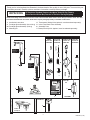
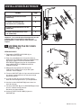
Remove the tting and loose items from the carton. The illustration below shows all the ttings and loose items after they
have been removed from the carton. Some items may be packaged partially assembled to other items.
UNPACKING
All American Standard Products Are Water Tested At Our Factory.
Some Residual Water May Remain In The Valve During Shipping.
1. Installation Instructions
2. Paradigm Spout Assembly (less mixing)
2a. Paradigm Spout Assembly (mixing)
3. Mounting Kit
4. Thermostatic Mixing Valve (optional, must be ordered separately)
5. Inline Filter/Check Valve Assembly
6. Assembly Parts
7. Battery Back-Up Unit (optional, must be ordered separately)
Deck Plate
Plug-In AC
Power Kit
Hard-Wired AC
Power Kit
Multi-AC
Power Kit
PWRX
Power Kit
PK00.PACPK00.WRK
PK00.HAC PK00.MAC
PK00.BBU
Battery
Back-Up
Kit
7
POWER KITS SOLD SEPARATELY
702P.400
Paradigm 4"
605XTMV1070
4
Mixing Valve
3
6
1
1
© 2018 AS America Inc.
Installat ion Inst ructions
© 2018 AS America, Inc.
NOTE TO INSTALLER: Please give this manual to the customer after installation.
To learn more about American Standard Selectronic
®
Products visit our website at: www.americanstandard-us.com
or e-mail us at: CRTTEAM@americanstandard.com
For Parts, Service, Warranty or other Assistance,
please call (844) CRT-TEAM / (844) 278-8326 (In Canada: 1-800-387-0369)
(In Toronto Area only: 1-905-306-1093)
Paradigm Integrated Faucet
with Optional Above-Deck
Mixing & SmarTherm
®
MODEL NUMBERS
7025.1xx 702B.1xx
7025.2xx 702B.2xx
7025.3xx 702B.3xx
M965985 (11/18)
CAUTION: Use only American Standard supplied
transformers and cable sets. Using non-AS supplied
cables, or cutting, splicing or modifying any components
will void the warranty.
Product No’.s & Options 2
3
Faucet Installation 3
Electrical Installation 4-5
FAQ’s / Troubleshooting 9
Parts 10
Start-up / Maintenance 6-8
2
5
DO NOT REMOVE
PROTECTIVE
FILM FROM
SENSOR EYE UNTIL
INSTALLATION IS
COMPLETE.
2a
5
DO NOT REMOVE
PROTECTIVE
FILM FROM
SENSOR EYE UNTIL
INSTALLATION IS
COMPLETE.

3
M965985 (11/18)
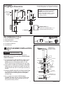
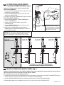
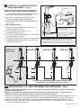
Paradigm
Roughing-in Dimensions
RECOMENDED CONTROL BOX OR
EQUIVALENT BY OTHERS
4" (102mm) SQ. X 2-1/2" (64mm) DEEP 2-GANG ELECTRICAL
BOX Appleton #4SD1 OR EQUAL (BY OTHERS).
(Used with Hard-Wired AC Transformer)
FINISHED WALL
OR BACKSPLASH
169 mm
(6-5/8")
192 mm
(7-1/2")
51 mm
(2")
28 mm
(Ø1-1/8")
3/8" COMPRESSION
CONNECTORS
189 mm
(7-1/2")
140 mm
(5-1/2")
38 mm
(1-1/2")
597 mm
(23-1/2")
39 mm
(1-1/2")
59 mm
(2-3/8")
CLEARANCE
25 mm (min)
(1" min)
Note: All plumbing and electrical wiring must be installed in
accordance with applicable codes, regulations and standards.
CAUTION: Use only American Standard
supplied transformers and cable sets.
Using non-AS supplied cables, or cutting,
splicing or modifying any components
will void the warranty.
1
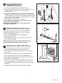
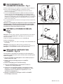
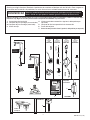
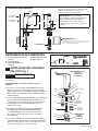
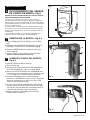
SPOUT ASSEMBLY INSTALLATION;
Fig. 1
1. Make sure O-RING (1) is installed in spout base.
IMPORTANT: Do not use putty when installing faucet
without escutcheon.
2. If installing DECK PLATE (2) (optional): Apply a bead
of putty to bottom edge of PUTTY PLATE (2). Install
SCREW (11) into the MOUNTING BASE OF THE
FAUCET (13) and allign SCREW (11) with HOLE (12).
3. Insert SUPPLY HOSES (3), SHANK (4) and SENSOR
CABLE (5) (only included in base model) through hole
in DECK PLATE with PUTTY PLATE (2) and mounting
surface.
4. Assemble RUBBER WASHER (7), BRASS WASHER (8)
and THREADED LOCKNUT (9) onto SHANK (4) from
underside of sink or mounting surface. Hand tighten
LOCKNUT (9).
5. Use a screwdriver to tighten SCREWS (10) on
LOCKNUT (9). Work your way around LOCKNUT (9),
tightening the screws slightly each time until all are
snug to ensure even pressure.
1. 2.5 mm Hex Wrench (Included)
2. Adjustable Wrench
3. Plumbers’ Putty or Caulking
4. Flat Blade Screwdriver
5. Tape Measure
RECOMMENDED TOOLS
CAUTION
Turn off hot and cold water
supplies before beginning
10
MOUNTING
SURFACE
TIGHTEN
SPIN NUTS
3
5
I
MPORTANT: Do not
use sealent on threads
Fig. 2
1
2
3
4
5
10'
Fig. 1
PUTTY
(If required)
(OPTIONAL)
2
1
4
12
13
7
8
9
I
MPORTANT: Do not
use putty when installing
faucet without escutcheon.
11

M965985 (11/18)
4
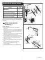
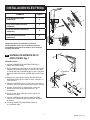
ELECTRICAL INSTALLATION
Product Page
PWRX Power Kit
(PK00.WRK)
4
Plug-In AC Power Kit (PK00.PAC)
5
Hard-Wired AC Power Kit (PK00.HAC)
5
Multi-AC Power Kit (PK00.MAC)
5
Important: All faucets with the standard CR-P2 battery
come preaseambled from the factory. No further action
necessary.
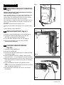
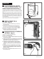
A
PWRX 10 YEAR BATTERY
SYSTEM; Fig. 1
PWRK
™
VERSION;
1. Connect PWRX BATTERY PACK (1) to SENSOR
CABLE (2).
2. Secure the connections by installing into CONNECTOR
LOCKING DEVICE (3) as shown. Rotate the END CAPS
(4) to secure the connection within the CONNECTOR
LOCKING DEVICE (3).
3. Determine the mounting location of the PWRX BATTERY
PACK (1) by marking center lines as shown.
4. Place the BRACKET (5) on the horizontal center line
and mark the location of the mounting holes to be drilled.
5. Using 1/4" diameter drill bit, drill two mounting holes
aproximately 1" deep.
6. Install the two ANCHORS (6) provided into the mounting
holes.
7. Place the BRACKET (5) over the ANCHORS (6)
and secure with the SCREWS (7) provided.
Do not overtighten.
8. Insert PWRX BATTERY PACK (1) into BRACKET (5).
7
6
5
VERTICAL
C/L
HORIZONTAL
C/L
1
BRACKET INSTALLATION
Fig. 1
1
3
2
3
4
4

M965985 (11/18)
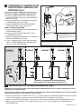
5
Unit #1
(Already Installed)
Fig. 3
Unit #2 Unit #3 Unit #4
1
2
4
3
MAXIMUM OF 15 UNITS PER TRANSFORMER.
10' MAXIMUM CABLE LENGTH BETWEEN UNITS.
BLACK & WHITE
POWER
CONNECTIONS
C
MULTI-AC VERSION (DAISY-CHAIN); Fig. 3
Important: Disconnect the rst unit’s Multi-AC Adapter from power supply before making daisy-chain connections.
Note: For Unit #1 electrical instructions, refer to Figure 2 (above).
For subsequent Units, refer to instructions below...
1. Connect one end of the 10' EXTENSION (1) to the available terminal of the previous unit’s MULTI-AC ADAPTER (2), and
the other end to the single terminal of the current unit’s MULTI-AC ADAPTER (3).
2. Connect SENSOR CABLE (4) to either of the two available terminals of MULTI-AC ADAPTER (3).
3. Repeat Steps above for each additional Unit, for a Max. of 15 Units on one AC POWER SUPPLY.
CAUTION: Use only American Standard supplied transformers
and cable sets. Using non-AS supplied cables, or cutting,
splicing or modifying any components will void the warranty.
B
AC VERSIONS (HARD-WIRED /
PLUG-IN POWER SUPPLY); Fig. 2
Important: Turn off power to outlet or electrical box.
FOR PLUG-IN VERSION;
1. Connect PLUG-IN AC POWER SUPPLY (2) to one end of
the SINGLE AC ADAPTER (6).
2. Connect SENSOR CABLE (4) to the other end of the
SINGLE AC ADAPTER (6).
3. Connect PLUG-IN AC POWER SUPPLY (2) to wall outlet.
FOR HARD-WIRED VERSION;
1. Connect HARD-WIRED AC TRANSFORMER (3) to
AC-DC CONVERTER (7).
2. Connect 10’ EXTENSION CABLE (1) to AC-DC
CONVERTER (7).
3. Connect SENSOR CABLE (4) to the other end of the
10' EXTENSION CABLE (1).
4. Make Black and White power line connections to
HARD-WIRED AC TRANSFORMER (3) and mount on
ELECTRICAL BOX (5).
Fig. 2
6
4
2
3
5
1
1
WALL
OUTLET
4" CONTROL BOX
OR EQUIVALENT BY
OTHERS (6)
BLACK & WHITE
POWER
CONNECTIONS
10' EXTENSION
7
AC-DC
CONVERTER
Do not connect power to transformer
until installation of faucet is complete.
Recommended Electrical Box or Equivalent
by others 4” (102mm) SQ. X 2-1/2” (64mm)
DEEP 2-GANG ELECTRICAL BOX Appleton
#4SD1 OR EQUAL (BY OTHERS).

6
M965985 (11/18)
Fig. 4
DETECTION
ZONE
PROTECTIVE FILM
IMPORTANT: Do not
use sealent on threads
1
2
3
COLD
HOT
(3) INLINE
FILTER
Fig. 6
5
4
Fig. 5
1
9
8
7
5
3
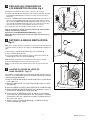
D
MAKE WATER SUPPLY
CONNECTIONS; Fig. 4
1. Turn off hot and cold water supplies before beginning.
2. Install INLINE FILTER (3) on each wall supply outlet. Be sure that
INLINE FILTER (3) is inserted in the correct direction.
(See Illustration)
3. Connect HOT FLEXIBLE SUPPLY (marked with red stripe) (1) to
INLINE FILTER (3) on hot water control stop (4). Connect COLD
FLEXIBLE SUPPLY (marked with blue stripe) (2) to INLINE FILTER
(3) on cold water control stop (5). Use adjustable wrench to tighten
connections. Do not over tighten.
4. Faucet supplies are 24" long from faucet base.
Note; If additional supply length is required, installer must
purchase those parts separately.
Important; If SUPPLY HOSES (1, 2) are too long, loop as
illustrated to avoid kinking.
E
REMOVE MIXING HANDLE; Fig. 5
Note: Before removing the handle, preset the desired water
temperature and while disassembling make sure to keep the
SHAFT EXTENSION (8) in place.
1. Unthread SET SCREW (3) and remove HANDLE (5).
2. Remove LIMIT STOP (1).
3. Using a Slotted screwdriver unthread SCREW (7) and remove
SHAFT EXTENSION (8).
Note: Hold the extension in place while unthreading the screw.
4. Install CAP (9) onto the Body and press until you hear a click.
Note: Sharper side faces towards the back of the body.
F
ADJUST HOT LIMIT STOP; Fig. 5, 6
To reduce the amount of hot water that can mix with cold, the
installer can adjust hot limit stop (Four different settings).
1. Rotate LEVER HANDLE (5) counter-clockwise to its stop position
(100% cold).
2. Remove SET SCREW (3) and pull off the LEVER HANDLE (5).
3. Pull out LIMIT STOP (1) from the SHAFT EXTENSION (8).
4. Rotate LIMIT STOP (1) between the shaded area and insert back
onto SHAFT EXTENSION (8).
5. Each notch on the LIMIT STOP (1) will reduce the amount of hot
water by approximately 3%. For example, the 2nd notch will have
97% of maximum temp, the 3rd notch will have 94% and the fourth
will be 91%.
6. Replace LEVER HANDLE (5), SET SCREW (3) and tighten.
1
2
Fig. 6

7
M965985 (11/18)
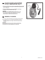
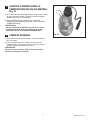
MAINTENANCE
A
HAND WASH SENSOR OPERATION;
Fig. 7
REMOVE PROTECTIVE FILM FROM SENSOR EYE WHEN
INSTALLATION IS COMPLETE.
When the Sensor detects a user, the water immediately starts
to ow. Water ow will stop 1.5 seconds after user is out of
sensor range. This Comfort delay allows the user to comfort-
ably move their hands without the water turning off.
As a precaution, a Safety Timer will turn off the water after the
sensor has been blocked for 59 seconds. The water will stay
off until the
blockage is removed from the detection zone.
The Comfort and Safety time settings can be adjusted using
the
Optional Remote Control (605XRCT).
B
REPLACE BATTERY; Fig. 8, 9
1. Remove 3 COVER SCREWS (1) and lift COVER (15) off.
2. Disconnect SENSOR CABLES (6) and (7) from the
BATTERY and SOLENOID VALVE. (Fig. 9)
3. Push BATTERY (17) forward and Pull it out. (Fig. 8)
4. Replace the new battery with the same placement.
(Insert terminal side rst)
C
CHANGE SENSOR RANGE;
Fig. 8, 9
1. Remove 3 COVER SCREWS (1).
2. Remove the COVER (15).
3. Disconnect the BLACK POWER SUPPLY CONNECTOR (7)
and reconnect. Fig. 9.
4. While the SENSOR CONTROL LED (9) is blinking slowly,
place your hand 1 - 2 in. (25.4-50.8mm) in front of the sensor.
5. When the LED stops blinking and stays “ON”, move your hand
to the desired position and hold in place until the LED begins
to blink again.
6. Once the SENSOR CONTROL LED (9) begins to blink
again,
remove your hand from the detection zone. When the ashing
stops, the detection distance is set.
7. Reassemble the COVER (15) and secure it with COVER
SCREWS (1).
15
16
2
1
4
9
14
7
Fig. 8
Fig. 9
6
12
17
Fig. 4
DETECTION
ZONE
PROTECTIVE FILM
IMPORTANT: Do not
use sealent on threads
1
2
3
COLD
HOT
(3) INLINE
FILTER
Fig. 6
5
4
Fig. 5
1
9
8
7
5
3
1
Fig. 7

8
M965985 (11/18)
D
ADJUST OR REPLACE MAXIMUM
OUTLET TEMPERATURE; Fig. 10
1. With the COVER off, the installer can reduce the maximum mixed
water temperature by turning the THERMO VALVE (4) clockwise
with a screwdriver.
2. Remove SCREW (6) and unthread THERMO VALVE (4).
Replace with new THERMO VALVE (4).
WARNING
• Do not turn the THERMO VALVE (4) More than 1 turn.
• The maximum mixed water temperature can not be
increased due to ASSE 1070 requirements.
E
GENERAL CLEANING
1. Only use a damp, soft cloth to clean the spout and the sensor.
2. For tougher dirt, use a soft cloth with diluted dish washing
detergent. Wipe the area using a wet cloth and dry using a
soft cloth.
CAUTION
Do not scratch the sensor when cleaning. Avoid using
any abrasives or harsh detergents or chemicals.
Fig. 12
4
1
2
3
6
5
Fig. 10

9
M965985 (11/18)
HOT LINE FOR HELP
For toll-free information and answers to your questions, call:
(844) CRT-TEAM / (844) 278-8326
IN CANADA 1-800-387-0369 (TORONTO 1-905-306-1093)
Weekdays 8:00 a.m. to 7:00 p.m. EST
IN MEXICO 01-800-839-1200
Product names listed herein are trademarks of AS America, Inc. ©2018
To learn more about American Standard Selectronic
®
Products visit our website at:
www.americanstandard-us.com or e-mail us at: CRTTEAM@
lixilamericas.com
Mon. - Fri. 8:00 a.m. to 8:00 p.m. EST Saturday 10:00 a.m. to 4:00 p.m. EST
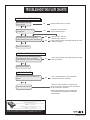
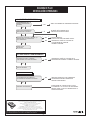
TROUBLESHOOTING FLOW CHARTS
UNIT DOES NOT FUNCTION
1 1
2 2
YES
YES
NO
NO
YES
NO
OPEN EXTERNAL SUPPLY STOPS.
CRITICALLY LOW BATTERY.
INSTALL NEW BATTERY.
DEAD BATTERY. INSTALL
NEW BATTERY. REPEAT.
NO
CHECK FOR DAMAGE TO SENSOR WIRE INSULATION.
REPLACE SENSOR.
ARE EXTERNAL SUPPLY
STOPS OPEN?
REPEATED DOUBLE FLASH
ON SENSOR?
RECONNECT BATTERY TO SENSOR.
DOES SENSOR FLASH FOR 5 SECONDS?
REPLACE SOLENOID
YES
YES
NO
CHECK FOR DAMAGE TO SENSOR WIRE INSULATION.
REPLACE SENSOR.
RECONNECT BATTERY TO SENSOR.
DOES SENSOR FLASH FOR 5 SECONDS?
NO
FULLY OPEN EXTERNAL SUPPLY STOPS BY
TURNING COUNTER CLOCKWISE.
INSPECT FILTER ASSEMBLY, AERATOR AND
SOLENOID VALVE. REMOVE, CLEAN AND INSERT
BACK TO ORIGINAL POSITION.
NOTE: AERATOR MUST ONLY BE SERVICED
WITH APPROPRIATE AMERICAN STANDARD
REPAIR PARTS.
CHECK FOR BLOCKAGE
ARE EXTERNAL SUPPLY STOPS FULLY
OPEN?
REPLACE SOLENOID
WATER IS CONTINUOUSLY RUNNING
LOW FLOW ISSUES

1
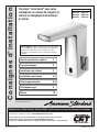
Consignes d’installation
Certié conforme aux exigences ASME A112.18.1.
© 2018 AS America, Inc.
REMARQUE À L’INTENTION DE L’INSTALLATEUR : Veuillez donner ce manuel au client après l’installation.
Pour en savoir plus sur les produits Selectronic® d’American Standard, visitez notre site Web au : www.americanstandard-us.com
ou écrivez-nous à l’adresse suivante : [email protected]
Pour les pièces, les services d’entretien, la garantie ou toute autre assistance,
veuillez communiquer avec nous au 844-CRT-TEAM/844-278-8326
(au Canada : 1-800-387-0369). (Dans la région de Toronto uniquement : 1-905-306-1093).
M965985 FR (11/18)
© 2018 AS America Inc.
Paradigm
™
Selectronic
®
avec valve
mélangeuse au-dessus du comptoir et
limiteur de température SmarTherm
™
en option
NUMÉROS DE MODÈLE
7025.1xx 702B.1xx
7025.2xx 702B.2xx
7025.3xx 702B.3xx
MISE EN GARDE : Utilisez uniquement les transformateurs
et les ensembles de câbles fournis par American Standard.
L’utilisation de câbles non fournis par AS, ou la coupe,
l’épissage ou la modication de tout composant annulera
la garantie.
Nos de produits et options 2
Caractéristiques 3
Installation du robinet 3
Installation électrique 4-5
FAQ/dépannage 9
Pièces 10
Démarrage/entretien 6-8

2
M965985 FR (11/18)
PK00.PACPK00.WRK
PK00.HAC PK00.MAC
PK00.BBU
7
702P.400
Paradigm 4"
Ensemble
d’alimentation
en C.A. xe
Ensemble
d’alimentation
par multi C.A.
Ensemble
d’alimentation
PWRX
Ensemble
d’alimentation
par branchement
C.A.
ENSEMBLES D'ALIMENTATION VENDUS SÉPARÉMENT
605XTMV1070
4
3
6
1
1
© 2018 AS America Inc.
Installat ion Inst ructions
© 2018 AS America, Inc.
NOTE TO INSTALLER: Please give this manual to the customer after installation.
To learn more about American Standard Selectronic
®
Products visit our website at: www.americanstandard-us.com
or e-mail us at: CRTTEAM@americanstandard.com
For Parts, Service, Warranty or other Assistance,
please call (844) CRT-TEAM / (844) 278-8326 (In Canada: 1-800-387-0369)
(In Toronto Area only: 1-905-306-1093)
Paradigm Integrated Faucet
with Optional Above-Deck
Mixing & SmarTherm
®
MODEL NUMBERS
7025.1xx 702B.1xx
7025.2xx 702B.2xx
7025.3xx 702B.3xx
M965985 (11/18)
CAUTION: Use only American Standard supplied
transformers and cable sets. Using non-AS supplied
cables, or cutting, splicing or modifying any components
will void the warranty.
Product No’.s & Options 2
3
Faucet Installation 3
Electrical Installation 4-5
FAQ’s / Troubleshooting 9
Parts 10
Start-up / Maintenance 6-8
Plaque de tablier
Valve mélangeuse
Ensemble de
piles de secours
2
5
2a
5
NE RETIREZ PAS LE
FILM DE PROTECTION
DE L'ŒIL DU CAPTEUR
AVANT D'AVOIR
TERMINÉ
L'INSTALLATION.
NE RETIREZ PAS LE
FILM DE PROTECTION
DE L'ŒIL DU
CAPTEUR AVANT
D'AVOIR TERMINÉ
L'INSTALLATION.
Merci d’avoir choisi American Standard… la référence en matière de qualité depuis plus de 100 ans. An de
garantir une installation sans problème, veuillez lire ces instructions attentivement avant de commencer.
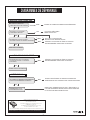
Retirez les raccords et les éléments en vrac de la boîte. L’illustration ci-dessous présente les raccords et les éléments en
vrac une fois retirés de la boîte. Certains éléments peuvent être emballés partiellement assemblés à d’autres éléments.
DÉBALLAGE
Tous les produits American Standard sont éprouvés avec de l’eau dans notre usine.
De l’eau résiduelle peut rester dans le robinet pendant le transport.
1. Consignes d’installation
2. Assemblage du bec Paradigm (sans mélangeur)
2a. Assemblage du bec Paradigm (avec mélangeur)
3. Ensemble d’installation
4. Valve mélangeuse thermostatique
(en option, doit être commandée séparément)
5. Assemblage du ltre en ligne et du clapet antiretour
6. Pièces d’assemblage
7. Unité de pile de secours
(en option, doit être commandée séparément)

3
M965985 FR (11/18)
169 mm
(6-5/8 po)
192 mm
(7-1/2 po)
51 mm
(2 po)
28 mm
(Ø1-1/8 po)
189 mm
(7-1/2 po)
140 mm
(5-1/2 po)
38 mm
(1-1/2 po)
597 mm
(23-1/2 po)
39 mm
(1-1/2 po)
59 mm
(2-3/8 po)
JEU DE 25 mm (min)
(1 po min)
MUR FINI OU
DOSSERET
RACCORDS À
COMPRESSION DE 3/8 po
BBOÎTIER DE COMMANDE RECOMMANDÉ OU L’ÉQUIVALENT
PROVENANT D’AUTRES FOURNISSEURS
BOÎTER ÉLECTRIQUE DOUBLE 4 po (102 mm) carrés X 2-1/2 po
(64 mm) de profondeur Appleton #4SD1 OU ÉQUIVALENT
PROVENANT D’AUTRES FOURNISSEURS).
(À utiliser avec un transformateur AC fixe)
1. Consignes d’installation
2. Assemblage du bec Paradigm (sans mélangeur)
2a. Assemblage du bec Paradigm (avec mélangeur)
3. Ensemble d’installation
4. Valve mélangeuse thermostatique
(en option, doit être commandée séparément)
5. Assemblage du ltre en ligne et du clapet antiretour
6. Pièces d’assemblage
7. Unité de pile de secours
(en option, doit être commandée séparément)
Dimensions d’installation
Remarque : L’ensemble de la tuyauterie et du câblage
électrique doivent être installés conformément aux codes,
réglementations et normes applicables.
MISE EN GARDE : Utilisez uniquement les
transformateurs et les ensembles de câbles
fournis par American Standard. L’utilisation
de câbles non fournis par AS, ou la coupe,
l’épissage ou la modication de tout
composant annulera la garantie.
1
INSTALLATION DU BEC – Fig. 1
1. Assurez-vous que le JOINT TORIQUE (1) est installé
dans la base du bec.
IMPORTANT : N’utilisez pas de mastic en cas
d’installation du robinet sans écusson.
2. Si vous installez la PLAQUE DE TABLIER (2)
(en option) : Appliquez un trait de mastic sur le bord
inférieur de la PLAQUE D’ÉTANCHÉITÉ (2). Installez
la VIS (11) dans la BASE DE MONTAGE DU ROBINET
(13) et alignez la VIS (11) avec le TROU (12).
3. Insérez les TUYAUX D’ALIMENTATION (3), la TIGE (4)
et le CÂBLE DU CAPTEUR (5) (inclus dans le modèle
de base uniquement) dans le trou de la PLAQUE DE
TABLIER avec la PLAQUE D’ÉTANCHÉITÉ (2)
et la surface de montage.
4. Assemblez la RONDELLE EN CAOUTCHOUC (7),
la RONDELLE EN LAITON (8) et le CONTRE-ÉCROU
FILETÉ (9) sur la TIGE (4) à partir de la sous-face
du lavabo ou de la surface de montage. Serrez le
CONTRE-ÉCROU (9) à la main.
5. Utilisez un tournevis pour serrer les VIS (10) sur le
CONTRE-ÉCROU (9). Serrez légèrement les vis du
CONTRE-ÉCROU (9) tour à tour jusqu’à ce qu’elles
soient bien ajustées an de garantir une pression
uniforme.
1. Clé hexagonale 2,5 mm
(incluse)
2. Clé à ouverture réglable
3. Mastic ou calfatage
4. Tournevis plat
5. Galon à mesurer
OUTILS RECOMMANDÉS
MISE EN
GARDE
Fermez l’alimentation en eau chaude et en
eau froide avant de commencer.
10
3
5
MASTIC
(si nécessaire)
SURFACE
DE MONTAGE
(EN OPTION)
SERREZ
LES ÉCROUS
À SERRAGE RAPIDE
IMPORTANT : N'utilisez pas de
mastic en cas d'installation
du robinet sans écusson.
IMPORTANT :
N’utilisez pas de
mastic sur les filets
Fig. 2
1
2
3
4
5
10'
Fig. 1
2
1
4
12
13
7
8
9
11

M965985 FR (11/18)
4
7
6
5
1
Fig. 1
1
3
2
3
4
4
LC VERTICALE
LC HORIZONTALE
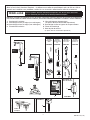
INSTALLATION DU SUPPORT
INSTALLATION ÉLECTRIQUE
Produit Page
Ensemble d’alimentation PWRX
(PK00.WRK)
4
Ensemble d’alimentation par
branchement C.A. (PK00.PAC)
5
Ensemble d’alimentation en C.A. xe
(PK00.HAC)
5
Ensemble d’alimentation par multi
C.A. (PK00.MAC)
5
Important : Les raccordements électriques de tous les
produits dotés d’une pile CR-P2 régulière sont
préassemblés à l’usine. Aucune autre mesure n’est
requise.
A
SYSTÈME DE PILE DE 10 ANS
PWRX – Fig. 1
VERSION PWRX™ :
1. Raccordez le PORTE-PILES PWRX (1) au
CÂBLE DU CAPTEUR (2).
2. Fixez ces raccordements en les installant dans le
DISPOSITIF DE VERROUILLAGE DU CONNECTEUR
(3), comme indiqué. Tournez les CAPUCHONS
D’EXTRÉMITÉ (4) pour bien xer le raccordement
dans le DISPOSITIF DE VERROUILLAGE DU
CONNECTEUR (3).
3. Déterminez l’emplacement de montage du
PORTE-PILES PWRX (1) en traçant des lignes
centrales, comme indiqué.
4. Placez le SUPPORT (5) sur la ligne centrale horizontale
et indiquez l’emplacement où les trous de montage
devront être percés.
5. À l’aide d’un foret de 1/4 po de diamètre, percez
deux trous de montage d’environ 1 po de profondeur.
6. Installez les deux ANCRAGES (6) fournis dans les
trous de montage.
7. Placez le SUPPORT (5) sur les ANCRAGES (6) et xez
le tout à l’aide des VIS (7) fournies.
Ne serrez pas excessivement.
8. Insérez le PORTE-PILES PWRX (1) dans le
SUPPORT (5).

M965985 FR (11/18)
5
Fig. 3
1
2
4
3
Unité no 1
(déjà installée)
Unité no 2 Unité no 3 Unité no 4
15 UNITÉS PAR TRANSFORMATEUR MAXIMUM. CÂBLE D’UNE
LONGUEUR DE 10 PI MAXIMUM ENTRE LES UNITÉS.
RACCORDEMENTS
ÉLECTRIQUES
NOIR ET BLANC
MISE EN GARDE : Utilisez uniquement les transformateurs
et les ensembles de câbles fournis par American Standard.
L’utilisation de câbles non fournis par AS, ou la coupe, l’épissage
ou la modication de tout composant annulera la garantie.
B
VERSIONS C.A. (ALIMENTATION FIXE/
PAR BRANCHEMENT) – Fig. 2
Important : Fermez l’alimentation vers la prise ou le
boîtier électrique. POUR LA VERSION BRANCHÉE :
1. Connectez l’ALIMENTATION CA À BRANCHER (2) à une
extrémité de l’ADAPTATEUR CA UNIQUE (6).
2. Connectez le CÂBLE DU CAPTEUR (4) à l’autre
extrémité de l’ADAPTATEUR CA UNIQUE (6).
3. Connectez l’ALIMENTATION CA À BRANCHER (2) à la
prise murale.
POUR LA VERSION FIXE :
1. Raccorder le TRANSFORMATEUR CA FIXE (3) au
CONVERTISSEUR CA-CC (7).
2. Raccorder la RALLONGE DE 10 PI (1) au
CONVERTISSEUR AC-CC (7).
3. Raccorder le CÂBLE DU CAPTEUR (4) à l’autre extrémité
de la RALLONGE DE 10 PI (1).
4. Connecter les raccords noir et blanc de la ligne électrique
au TRANSFORMATEUR CA FIXE (3) et le xer sur le
BOÎTIER ÉLECTRIQUE (5).
C
VERSION MULTI C.A. (RACCORDEMENT EN GUIRLANDE) – Fig. 3
Important : Déconnectez l’adaptateur multi c.a. de la première unité de l’alimentation électrique avant d’effectuer
les connexions en guirlande.
Remarque : Pour obtenir des consignes concernant l’installation électrique de l’unité no 1, reportez-vous à
la gure 2 (ci-dessus). Pour les autres unités, consultez les instructions ci-dessous...
1. Connectez une extrémité du CÂBLE D’EXTENSION DE 10 PI (1) à la borne disponible de l’ADAPTATEUR MULTI C.A.
(2) de l’unité précédente, et l’autre extrémité à la borne unique de l’ADAPTATEUR MULTI C.A. (3) de l’unité actuelle.
2. Connectez le CÂBLE DU CAPTEUR (4) à l’une des deux bornes disponibles de l’ADAPTATEUR MULTI C.A. (3).
3. Répétez les étapes ci-dessus pour chaque unité supplémentaire, en veillant à ne pas excéder la limite maximale de
15 unités par ALIMENTATION EN C.A.
Fig. 2
6
4
2
3
5
1
1
PRISE DE
COURANT
MURALE
BOÎTIER DE
COMMANDE DE 4
PO OU ÉQUIVALENT
FOURNI PAR D’AUTRES
FOURNISSEURS
RACCORDEMENTS
ÉLECTRIQUES
NOIR ET BLANC
CÂBLE D’EXTENSION
DE 10 PI
7
CONVERTISSEUR
CA-CC
Ne branchez pas l’alimentation au
transformateur avant de terminer
l’installation du robinet.
Boîtier électrique recommandé ou équivalent
provenant d’autres fournisseurs BOÎTIER
ÉLECTRIQUE DOUBLE 4 po (102 mm) carrés.
X 2-1/2 po (64 mm) de profondeur Appleton
#4SD1 OU ÉQUIVALENT PROVENANT
D’AUTRES FOURNISSEURS).

6
M965985 FR (11/18)
Fig. 4
1
2
3
Fig. 6
5
4
IMPORTANT : N’utilisez pas
de mastic sur les filets.
FROID
CHAUD
(3) FILTRE
EN LIGNE
ZONE DE
DÉTECTION
FILM DE
PROTECTION
Fig. 5
1
9
8
7
5
3
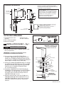
D
RACCORDEMENTS DE
L’ALIMENTATION EN EAU – Fig. 4
1. Fermez l’alimentation en eau chaude et en eau froide avant de commencer.
2. Placez chaque FILTRE EN LIGNE (3) sur chaque prise murale .
Assurez-vous que le FILTRE EN LIGNE (3) est inséré dans la bonne
direction (voir l’illustration).
3. Connectez l’ALIMENTATION EN EAU CHAUDE FLEXIBLE (identiée par
la bande rouge) (1) à la FILTRE EN LIGNE (3) à la soupape de contrôle
d’eau chaude (4). Connectez l’ALIMENTATION EN EAU FROIDE FLEXIBLE
(identiée par la bande bleue) (2) à la FILTRE EN LIGNE (3) à la soupape de
contrôle d’eau froide (5). Utilisez une clé ajustable pour serrer les raccords.
Veillez à ne pas trop serrer.
4. Les tuyaux d’alimentation du robinet ont une longueur de 24 po à partir de la
base du robinet.
Remarque : Si une longueur plus importante est requise, l’installateur doit
acheter les pièces nécessaires séparément. Important : Si les TUYAUX
D’ALIMENTATION (1, 2) sont trop longs, enroulez-les comme indiqué sur
l’illustration pour éviter toute formation de coudes.
E
RETIRER LA POIGNÉE DU MÉLAN-
GEUR
– Fig. 5
Remarque : Avant de retirer la poignée, régler la température de l’eau désirée,
et veiller à tenir l’EXTENSION DE LA TIGE (8) en place pendant que vous
démontez le produit.
1. Dévisser la VIS DE PRESSION (3) et retirer la POIGNÉE (5).
2. Retirer le LIMITEUR (1).
3. À l’aide d’un tournevis à cran, dévisser la VIS (7) et retirer l’EXTENSION DE
LA TIGE (8).
Remarque : Tenir l’extension en place lorsque vous dévissez la vis.
3. Installer le CAPUCHON (9) sur le corps et appuyer jusqu’à entendre un clic.
Remarque : Le côté pointu doit être tourné vers l’arrière du corps.
F
RÉGLAGE DU LIMITEUR D’EAU
CHAUDE – Fig. 5, 6
An de réduire la quantité d’eau chaude pouvant être mélangée à
l’eau froide, l’installateur peut ajuster le limiteur d’eau chaude (quatre
différents réglages).
1. Tournez la POIGNÉE À LEVIER (3) dans le sens antihoraire jusqu’à sa
position d’arrêt (100 % froid).
2. Retirez la VIS DU LEVIER (5) et enlevez la POIGNÉE À
LEVIER (3).
3. Retirez le LIMITEUR (1) de la TIGE DE VALVE (5).
4. Tournez le LIMITEUR (1) entre la zone ombrée et insérez-le à
nouveau sur la TIGE DE VALVE (5).
5. Chaque cran sur le LIMITEUR (1) réduira la quantité d’eau chaude
d’environ 3 %. Par exemple, le deuxième cran représente 97 % de la
température maximum, le troisième cran représente 94 %, et le
quatrième cran représente 91 %.
6. Replacez la POIGNÉE À LEVIER (3) et la VIS DE LA POIGNÉE
À LEVIER (5), et serrez le tout.
1
2
Fig. 6

7
M965985 FR (11/18)
Fig. 4
1
2
3
Fig. 6
5
4
IMPORTANT : N’utilisez pas
de mastic sur les filets.
FROID
CHAUD
(3) FILTRE
EN LIGNE
ZONE DE
DÉTECTION
FILM DE
PROTECTION
Fig. 5
1
9
8
7
5
3
7
Fig. 9
6
ENTRETIEN
A
FONCTIONNEMENT DU CAPTEUR
POUR LE LAVAGE DES MAINS – Fig. 7
RETIREZ LE FILM DE PROTECTION DE L’ŒIL DU
CAPTEUR LORSQUE L’INSTALLATION EST TERMINÉE.
Lorsque le capteur détecte un utilisateur, l’eau commence à s’écouler
immédiatement. L’eau cesse de couler 1,5 seconde après que l’utilisa-
teur
est passé hors de la portée du capteur. Ce délai de sécurité permet à
l’utilisateur de bouger les mains sans que l’eau ne cesse de couler.
Par mesure de précaution, une minuterie de sécurité coupe l’eau après
que le capteur a été bloqué pendant 59 secondes. Le robinet d’eau
restera fermé jusqu’à ce que la source du blocage du capteur sorte de
la zone de détection.
Les paramètres du délai et de la minuterie de sécurité peuvent être
réglés à l’aide de la télécommande en option (605XRCT).
B
REMPLACEMENT DE LA
PILE – Fig. 8, 9
1. Retirez les 3 VIS DU COUVERCLE (1) et soulevez le
COUVERCLE(15).
2. Déconnectez les CÂBLES DU CAPTEUR (6) et (7)
de la PILE et de la VALVE DE SOLÉNOÏDE. (Fig. 9)
3. Poussez la PILE (17) vers l’avant et retirez-la. (Fig. 8)
4. Replacez la nouvelle pile au même endroit
(insérez le côté de la borne en premier).
C
MODIFICATION DE LA PORTÉE DU
CAPTEUR – Fig. 8, 9
1. Retirez les 3 VIS DU COUVERCLE (1).
2. Retirez le COUVERCLE (15).
3. Déconnectez le CONNECTEUR D’ALIMENTATION NOIR (7)
et reconnectez-le. Fig. 9.
4. Pendant que la DEL DE LA COMMANDE DU CAPTEUR (9)
clignote lentement, placez votre main devant le capteur à une
distance de 1 à 2 po (25,4 à 50,8 mm) de celui-ci.
5. Lorsque la DEL arrête de clignoter et reste en position
« MARCHE », déplacez votre main à l’endroit souhaité et
maintenez-la en place jusqu’à ce que la DEL recommence à
clignoter.
6. Lorsque la DEL DE LA COMMANDE DU CAPTEUR (9)
recommence à clignoter, enlevez votre main de la zone de
détection. Lorsque le clignotement s’arrête, la distance de
détection est réglée.
7. Réassemblez le COUVERCLE (15) et xez-le avec la VIS
DU COUVERCLE (1).
Fig. 7
15
16
2
1
4
9
14
Fig. 8
12
17
1

8
M965985 FR (11/18)
Fig. 12
4
1
2
3
6
5
Fig. 10
D
AJUSTEMENT OU REMPLACEMENT DE
LA TEMPÉRATURE MAXIMALE DE LA
SORTIE – Fig. 10
1. Lorsque le couvercle est enlevé, l’installateur peut réduire la
température maximum de l’eau mitigée en tournant le CAPUCHON
DE LA VALVE (4) dans le sens horaire à l’aide d’un tournevis.
2. Retirez la VIS (6) et deletez le ROBINET THERMOSTATIQUE (4).
Remplacez-le par le nouveau ROBINET THERMOSTATIQUE (4).
AVERTISSEMENT
• Ne tournez pas le CAPUCHON DE LA VALVE (4) plus d’un tour.
• La température maximum de l’eau mitigée ne peut pas être
augmentée en raison des exigences ASSE 1070.
E
NETTOYAGE GÉNÉRAL
1. Utilisez uniquement un chiffon doux et humide pour
nettoyer le bec et le capteur.
2. En cas de saleté plus tenace, utilisez un chiffon doux avec
du détergent à vaisselle dilué. Frottez la zone avec un chif
fon humide et séchez-la avec un chiffon doux.
MISE EN GARDE
Veillez à ne pas rayer le capteur lors du nettoyage. Évitez d’utiliser
des détergents ou des produits abrasifs ou puissants.

9
M965985 FR (11/18)
DIAGRAMMES DE DÉPANNAGE
L'UNITÉ NE FONCTIONNE PAS.
1 1
2 2
OUI
OUI
NON
NON
OUI
NON
OUVREZ LES VANNES D'ALIMENTATION EXTÉRIEURES.
LA PILE EST TRÈS FAIBLE.
REMPLACEZ LA PILE.
PILE À PLAT. INSTALLEZ UNE
NOUVELLE PILE. RÉPÉTEZ L'ÉTAPE.
NON
VÉRIFIEZ SI L'ISOLATION DU CÂBLE DU CAPTEUR
EST ENDOMMAGÉE. REMPLACEZ LE CAPTEUR.
LES VANNES D'ALIMENTATION
EXTÉRIEURES SONT-ELLES OUVERTES?
LE CAPTEUR A-T-IL UN DOUBLE
CLIGNOTEMENT RÉPÉTITIF?
RECONNECTEZ LA PILE AU CAPTEUR.
LE CAPTEUR CLIGNOTE-T-IL PENDANT 5 SECONDES?
REMPLACEZ LE SOLÉNOÏDE.
OUI
OUI
NON
VÉRIFIEZ SI L'ISOLATION DU CÂBLE DU CAPTEUR
EST ENDOMMAGÉE. REMPLACEZ LE CAPTEUR.
RECONNECTEZ LA PILE AU CAPTEUR.
LE CAPTEUR CLIGNOTE-T-IL PENDANT
5 SECONDES?
NON
OUVREZ COMPLÈTEMENT LES VANNES D'ALIMENTATION
EXTÉRIEURES EN LES TOURNANT DANS LE SENS ANTIHORAIRE.
INSPECTEZ L’ASSEMBLAGE DU FILTRE, L’AÉRATEUR ET LA
VALVE DE SOLÉNOÏDE. RETIREZ, NETTOYEZ ET REMETTEZ
LE FILTRE À SON EMPLACEMENT INITIAL.
VÉRIFIEZ QU’IL N’Y A
PAS D’OBSTRUCTION.
LES VANNES D'ALIMENTATION EXTÉRIEURES
SONT-ELLES ENTIÈREMENT OUVERTES?
REMPLACEZ LE SOLÉNOÏDE.
L'EAU COULE SANS CESSE
DÉBIT FAIBLE
SERVICE D'ASSISTANCE TÉLÉPHONIQUE
Pour toutes questions, composez sans frais le numéro suivant :
844-CRT-TEAM / 844-278-8326
Les noms des produits indiqués dans la présente sont des marques de commerce d’AS America Inc. ©2017
Pour en savoir plus sur les produits Selectronic® d'American Standard, visitez notre site Web au
www.americanstandard-us.com, ou envoyez-nous un courriel à l'adresse suivante : CR[email protected]
Du lundi au vendredi de 8 h à 20 h, HNE Samedi de 10 h à 16 h
AU MEXIQUE 01-800-839-1200
AU CANADA 1-800-387-0369 (TORONTO 1-905-306-1093)
Du lundi au vendredi de 8 h à 19 h, HNE

1
Instrucciones de instalación
Certicado de cumplimiento con ASME A112.18.1
© 2017 AS America, Inc
NOTA PARA EL INSTALADOR: Entregue este manual al cliente después de la instalación.
Para obtener más información sobre los productos Selectronic® de American Standard, visite nuestro sitio web: www.amer-
icanstandard-us.com o escríbanos a: [email protected]
Para piezas, servicio, garantía u otra asistencia, llame al
(844) CRT-TEAM / (844) 278-8326 (En Canadá: 1-800-387-0369)
(Únicamente en el área de Toronto: 1-905-306-1093)
NÚMEROS DE MODELO:
7025.1xx 702B.1xx
7025.2xx 702B.2xx
7025.3xx 702B.3xx
M965985 SP (11/18)
© 2018 AS America Inc.
Paradigm
™
Selectronic
®
Llave Integrada
con Mezcladora Encima de la Plataforma
y Limitador de Temperatura SmarTherm
™
Opcionales
PRECAUCIÓN: Use únicamente los transformadores
y cables suministrados por American Standard. Si
utiliza cables no suministrados por AS o corta, separa o
modica cualquier componente, se anulará la garantía.
Nro. de producto y opciones 2
Especicaciones 3
Instalación de la llave 3
Instalación eléctrica 4-5
Preguntas frecuentes /
Resolución de problemas
Piezas 10
Inicio / Mantenimiento 6-8
9

2
M965985 SP (11/18)
PK00.PACPK00.WRK
PK00.HAC PK00.MAC
PK00.BBU
7
702P.400
Paradigm 4"
Kit de
electricidad
Enchufe AC
Kit de
electricidad
Cableado AC
Kit de
electricidad
Multi AC
Kit de
electricidad
PWRX
LOS KITS DE ELECTRICIDAD SE VENDEN POR SEPARADO
Kit de
reemplazo
de la batería
605XTMV1070
4
3
6
1
1
© 2018 AS America Inc.
Installat ion Inst ructions
© 2018 AS America, Inc.
NOTE TO INSTALLER: Please give this manual to the customer after installation.
To learn more about American Standard Selectronic
®
Products visit our website at: www.americanstandard-us.com
or e-mail us at: CRTTEAM@americanstandard.com
For Parts, Service, Warranty or other Assistance,
please call (844) CRT-TEAM / (844) 278-8326 (In Canada: 1-800-387-0369)
(In Toronto Area only: 1-905-306-1093)
Paradigm Integrated Faucet
with Optional Above-Deck
Mixing & SmarTherm
®
MODEL NUMBERS
7025.1xx 702B.1xx
7025.2xx 702B.2xx
7025.3xx 702B.3xx
M965985 (11/18)
CAUTION: Use only American Standard supplied
transformers and cable sets. Using non-AS supplied
cables, or cutting, splicing or modifying any components
will void the warranty.
Product No’.s & Options 2
3
Faucet Installation 3
Electrical Installation 4-5
FAQ’s / Troubleshooting 9
Parts 10
Start-up / Maintenance 6-8
Placa para plataforma
Válvula mezcladora
2
5
2a
5
NO RETIRE LA
PELÍCULA
PROTECTORA DEL
OJO DEL SENSOR
HASTA COMPLETAR
LA INSTALACIÓN.
NO RETIRE LA
PELÍCULA
PROTECTORA DEL
OJO DEL SENSOR
HASTA COMPLETAR
LA INSTALACIÓN.
Gracias por elegir American Standard, el parámetro de excelente calidad por más de 100 años. Para asegurarse
de realizar una instalación sin problemas, lea estas instrucciones cuidadosamente antes de comenzar.
Retire la conexión y los artículos ojos de la caja. La ilustración muestra todas las conexiones y todos los artículos ojos
fuera de la caja. Algunos artículos pueden haberse empacado ensamblados en parte a otros.
DESEMPACAR
Todos los productos de American Standard son probados con agua en nuestra
fábrica. Puede ser que quede un resto de agua en la válvula durante el envío.
1. Instrucciones de instalación
2. Conjunto del pico Paradigm (sin mezclador)
2a. Conjunto del pico Paradigm (mezclador)
3. Kit de montaje
4. Válvula mezcladora termostática (opcional, debe pedirse por
separado)
5. Conjunto de ltro incorporado/válvula de retención
6. Partes del conjunto
7. Unidad de reemplazo de la batería (opcional, debe pedirse por separado)
La page est en cours de chargement...
La page est en cours de chargement...
La page est en cours de chargement...
La page est en cours de chargement...
La page est en cours de chargement...
La page est en cours de chargement...
La page est en cours de chargement...
-
 1
1
-
 2
2
-
 3
3
-
 4
4
-
 5
5
-
 6
6
-
 7
7
-
 8
8
-
 9
9
-
 10
10
-
 11
11
-
 12
12
-
 13
13
-
 14
14
-
 15
15
-
 16
16
-
 17
17
-
 18
18
-
 19
19
-
 20
20
-
 21
21
-
 22
22
-
 23
23
-
 24
24
-
 25
25
-
 26
26
-
 27
27


American Standard 7025115.002 Guide d'installation
- Catégorie
- Articles sanitaires
- Taper
- Guide d'installation
- Ce manuel convient également à
dans d''autres langues
Documents connexes
-
American Standard 702B103.295 Guide d'installation
-
-
-
-
-
-
-
-
-