LG LMU363HV Mode d'emploi
- Catégorie
- Climatiseurs split-system
- Taper
- Mode d'emploi

Multi Type
Please read this installation manual completely before installing the product.
Installation work must be performed in accordance with the national wiring
standards by authorized personnel only.
Please retain this installation manual for future reference after reading it
thoroughly.
INSTALLATION MANUAL
AIR
CONDITIONER
MFL63260126
Rev.00_042022
www.lghvac.com
www.lg.com
Copyright © 2022 LG Electronics Inc. All Rights Reserved.
ENGLISH FRANÇAIS ESPAÑOL
*MFL63260126*

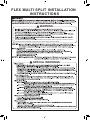
FLEX MULTI SPLIT INSTALLATION
INSTRUCTIONS
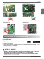
Do not turn on the breaker or power under condition that front panel, cabinet, top cover, control box cover are
removed or opened. Otherwise, it may cause fire, electric shock, explosionor death.
WARNING
!
SPECIAL WARNINGS
!

Installation Manual 3
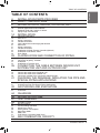
TABLE OF CONTENTS
ENGLISH
4 INSTALLATION PARTS PROVIDED
5 SAFETY INSTRUCTIONS
8 INSTALLATION OF INDOOR, OUTDOOR UNIT
8 Select the best location
10 Seaside Applications and Installation
11 Seasonal Wind And Cautions In Winter
12 Piping length and elevation
14 INSTALLATION
14 Connecting the piping
18 How To Fix
19 Wiring Connection
19 Conduit connection
20 Ceiling dimension and hanging bolt location
21 How to Fix
21 Wiring Connection
21 Conduit connection
22 Installation of Wired Remote Controller(Optional)
24 Installation of Decorative Panel
26 Drain Piping
29 FLARING WORK AND CONNECTION OF PIPING
29 Flaring work
30 Connection of piping - Outdoor
33 Installation
34 Installation of The Main Unit
35 CONNECTING THE CABLE BETWEEN INDOOR UNIT,
DISTRIBUTOR UNIT AND OUTDOOR UNIT
35 Connect the cable to the Indoor unit
36 Connect the cable to the Distributor unit
38 Connect the cable to the Outdoor unit
40 Connection method of the connecting cable(Example)
41 CHECKING THE DRAINAGE, INSULATING THE PIPE AND
SPECIAL PIPING APPLICATIONS
41 Checking the drainage
41 Insulating the Pipe and Special Piping Applications
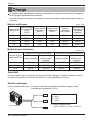
42 AIR PURGING AND EVACUATION
42 Leak Checking
43 Evacuation
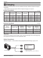
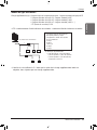
44 CHARGING
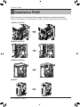
46 INSTALLATION PI485
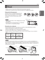
47 TEST RUNNING
48 FUNCTION
48 DIP S/W Setting
49 Forced Cooling Operation
50 Wiring Error Check
50 Saving Power Consumption
51 Night Quiet Mode
52 Mode Lock
53 PCB Display(18/24/60 k Model Only)
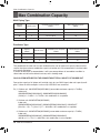
54 MAX COMBINATION CAPACITY
TABLE OF CONTENTS

4Multi Air Conditioner
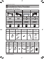
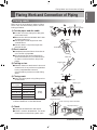
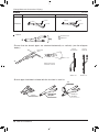
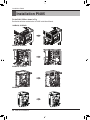
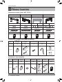
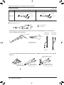
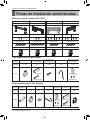
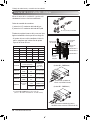
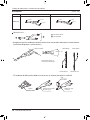
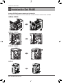
Installation Parts Provided
Installation Parts Provided
[Wall mounted / ART COOL Mirror]
[Ceiling Concealed Duct Type]
[Ceiling Cassette Type]
Type "A" screw Type "A" screw
Type "B" screw Type "B" screw
Remote control holderRemote control holder
Type 1 Type 2
Installation plate Installation plate
Type “A” screw Type “A” screw
Type "B" screw Type "C" screw Type "B" screw Type "C" screw
Remote control holderRemote control holder
Type 3 Type 4
Installation plate Installation plate
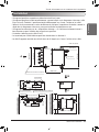
Name
Quantity
Shape for gas pipe
for liquid pipe
Clamp metal
1 EA
Insulation for
fitting
1 set
Clamp
8 EA
Screws for
duct flanges
1 set
Conduit Bracket
Screw(M4) 2 EA
Conduit
Bracket
1 EA
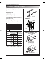
Name
Quantity
Shape for gas pipe
Conduit Bracket
Screw(M4) 2 EA
for liquid pipe
Clamp metal
1 EA
Insulation for Remote
control holderfitting
1 SET 1 EA
Drain hose
1 EA
Clamp Conduit
Bracket
8 EA
Washer for
hanging backet
8 EA 1 EA

Installation Manual 5
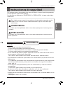
Safety Instructions
ENGLISH
hThe figure can be changed according to model.
Safety Instructions
Installation
• Always perform grounding.
- Otherwise, it may cause electrical shock.
• Don’t use a power cord, a plug or a loose socket which is damaged.
- Otherwise, it may cause a fire or electrical shock.
• For installation of the product, always contact the service center or a professional installation
agency.
- Otherwise, it may cause a fire, electrical shock, explosion or injury.
• Securely attach the electrical part cover to the indoor unit and the service panel to the outdoor
unit.
- If the electrical part cover of the indoor unit and the service panel of the outdoor unit are not
attached securely, it could result in a fire or electric shock due to dust, water, etc.
• Always install an air leakage breaker and a dedicated switching board.
- No installation may cause a fire and electrical shock.
• Do not keep or use flammable gases or combustibles near the air conditioner.
- Otherwise, it may cause a fire or the failure of product.
• Ensure that an installation frame of the outdoor unit is not damaged due to use for a long time.
- It may cause injury or an accident.
• Do not disassemble or repair the product randomly.
- It will cause a fire or electrical shock.
• Do not install the product at a place that there is concern of falling down.
- Otherwise, it may result in personal injury.
WARNING
!
The following safety guidelines are intended to prevent unforeseen risks or damage from
unsafe or incorrect operation of the appliance.
The guidelines are separated into ‘WARNING’ and ‘CAUTION’ as described below.
WARNING
This indicates that the failure to follow the instructions can cause serious injury or death.
CAUTION
This indicates that the failure to follow the instructions can cause the minor injury or
damage to the product.
This symbol is displayed to indicate matters and operations that can cause risk.
Read the part with this symbol carefully and follow the instructions in order to avoid risk.
!
!
!

6Multi Air Conditioner
Safety Instructions
• Use caution when unpacking and installing.
- Sharp edges may cause injury.
• Use a vacuum pump or Inert (nitrogen) gas when doing leakage test or air purge. Do not
compress air or Oxygen and Do not use Flammable gases. Otherwise, it may cause fire or
explosion.
- There is the risk of death, injury, fire or explosion.
Operation
• Do not share the outlet with other appliances.
- It will cause an electric shock or a fire due to heat generation.
• Do not use the damaged power cord.
- Otherwise, it may cause a fire or electrical shock.
• Do not modify or extend the power cord randomly.
- Otherwise, it may cause a fire or electrical shock.
• Take care so that the power cord may not be pulled during operation.
- Otherwise, it may cause a fire or electrical shock.
• Unplug the unit if strange sounds, smell, or smoke comes from it.
- Otherwise, it may cause electrical shock or a fire.
• Keep the flames away.
- Otherwise, it may cause a fire.
• Take the power plug out if necessary, holding the head of the plug and do not touch it with wet
hands.
- Otherwise, it may cause a fire or electrical shock.
• Do not use the power cord near the heating tools.
- Otherwise, it may cause a fire and electrical shock.
• Do not open the suction inlet of the indoor/outdoor unit during operation.
- Otherwise, it may electrical shock and failure.
• Do not allow water to run into electrical parts.
- Otherwise, it may cause the failure of machine or electrical shock.
• Hold the plug by the head when taking it out.
- It may cause electric shock and damage.
• Never touch the metal parts of the unit when removing the filter.
- They are sharp and may cause injury.
• Do not step on the indoor/outdoor unit and do not put anything on it.
- It may cause an injury through dropping of the unit or falling down.
• Do not place a heavy object on the power cord.
- Otherwise, it may cause a fire or electrical shock.
• When the product is submerged into water, always contact the service center.
- Otherwise, it may cause a fire or electrical shock.
• Take care so that children may not step on the outdoor unit.
- Otherwise, children may be seriously injured due to falling down.

Installation Manual 7
Safety Instructions
ENGLISH
Installation
• Install the drain hose to ensure that drain can be securely done.
- Otherwise, it may cause water leakage.
• Install the product so that the noise or hot wind from the outdoor unit may not cause any damage
to the neighbors.
- Otherwise, it may cause dispute with the neighbors.
• Always inspect gas leakage after the installation and repair of product.
- Otherwise, it may cause the failure of product.
• Keep level parallel in installing the product.
- Otherwise, it may cause vibration or water leakage.
Operation
• Avoid excessive cooling and perform ventilation sometimes.
- Otherwise, it may do harm to your health.
• Use a soft cloth to clean. Do not use wax, thinner, or a strong detergent.
- The appearance of the air conditioner may deteriorate, change color, or develop surface flaws.
• Do not use an appliance for special purposes such as preserving animals vegetables, precision
machine, or art articles.
- Otherwise, it may damage your properties.
• Do not place obstacles around the flow inlet or outlet.
- Otherwise, it may cause the failure of appliance or an accident.
CAUTION
!
• Do not install the unit in potentially explosive atmospheres.

8Multi Air Conditioner
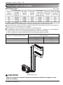
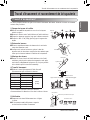
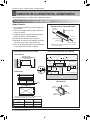
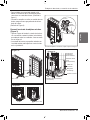
Installation of Indoor, Outdoor Unit
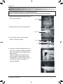
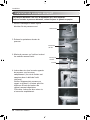
Read completely, then follow step by step.
Indoor unit
1. Do not have any heat or steam near the unit.
2. Select a place where there are no obstacles in
front of the unit.
3. Make sure that condensation drainage can be
conveniently routed away.
4. Do not install near a doorway.
5. Ensure the unit is unobstructed, allow proper
space on all sides according to the arrows and
distance measurements in the figures.
6.
Use a Metal Detector or Metal Scanner to locate
studs to prevent unnecessary damage to the wall.
Select the best location
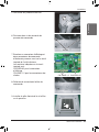
Top view
Front view
H=20(25/32) or more
Service Space
Ceiling
A
B
Capacity(Btu/h class)
AB
9/12 k 600(23-5/8) 900(35-7/16)
18 k 600(23-5/8)
1 100(43-5/16)
Unit: mm(inch)
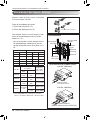
[Ceiling Concealed Duct Type] [Ceiling Cassette Type]
[ART COOL Gallery]
* Suitable dimention “H” is necessary to get a slope to
drain as show in the figure.
600
(23-5/8)
600
(23-5/8)
Inspection hole
[600(23-5/8) x 600(23-5/8)]
Control box
Ceiling
Ceiling Board Ceiling Board
Unit: mm(inch)
At least 1 800(70-
7
/
8
)
3 600(141-
23
/
32
) or less
1 000(39-
3
/
8
)
or more
500(19-
11
/
16
)
or more
10(
13
/
32
)
or more
500(19-11/16)
or more
300(11-
13
/16) or less
30(1-3/16)
±3(1/8)
More than
200(7-87/100)
More than
500(19-11/16)
More than
1 500(59-11/200)
More than
500(19-11/16)
FloorFloorFloor
More than 200(7-7/8)
Recommended height
2 000(78-3/4)
More than
100(3-15/16)
More than
100(3-15/16)
Unit:mm(inch)
[Wall mounted / ART COOL Mirror]
❈
Note : remove obstructions to prevent blockage of airflow path
Floor
Installation of Indoor, Outdoor Unit

Installation Manual 9
Installation of Indoor, Outdoor Unit
ENGLISH
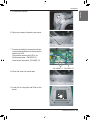
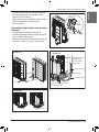
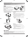
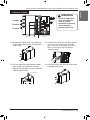
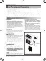
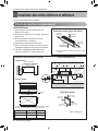
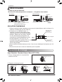
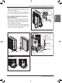
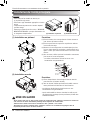
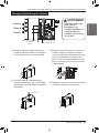
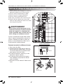
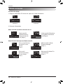
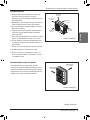
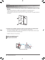
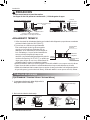
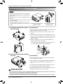
Outdoor unit
1. If an awning is built over the unit to prevent di-
rect sunlight or rain exposure, make sure that
heat radiation from the condenser is not re-
stricted.
2. Ensure the unit is unobstructed, allow proper
space on all sides according to the arrows
and distance measurements in the figures.
3. Do not place animals and plants in the path of
the warm air.
4. Take the air conditioner weight into account
and select a place where noise and vibration
are minimum.
5.
Select a place so that the warm air and sound
from the air conditioner does not disturb
neighbors.
6. Place that can sufficiently endure the weight
and vibration of the outdoor unit and where
even installation is possible.
7. Place that has no direct influence of snow or
rain.
8. Place with no danger of snowfall or icicle drop.
9. Place without weak floor or base such as de-
crepit part of the building or with a lot of snow
accumulation.
Rooftop Installations:
If the outdoor unit is installed on a roof structure,
be sure to level the unit. Ensure the roof struc-
ture and anchoring method are adequate for the
unit location. Consult local codes regarding
rooftop mounting.
more than
700 (27 9/16)
more than
300 (11 13/16)
more than
600 (23 21/32)
more than
300 (11 13/16)
more than
600 (23 21/32)
Unit:mm(inch)
more than 300
(11 13/16)
more than 300
(11 13/16)
Unit:mm(inch)

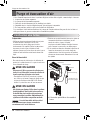
10 Multi Air Conditioner
Installation of Indoor, Outdoor Unit
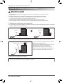
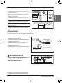
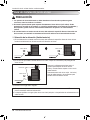
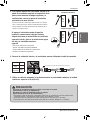
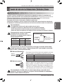
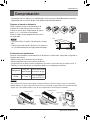
Seaside Applications and Installation
1.
Air conditioners should not be installed in areas where corrosive gases, such as acid or alkaline gas, are
produced.
2. Do not install the product where it could be exposed to sea wind (salty wind) directly. It can result
corrosion on the product. Corrosion, particularly on the condenser and evaporator fins, could
cause product malfunction or inefficient performance.
3. If outdoor unit is installed close to the seaside, it should avoid direct exposure to the sea wind.
1) If the outdoor unit is to be installed close to the seaside, direct exposure to the sea wind should be avoided.
Install the outdoor unit on the opposite side of the sea wind direction.
2)
In case, to install the outdoor unit on the seaside, set up a windbreaker/barrier, to lessen the unit's exposure to sea air
3) Select a well-drained place.
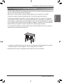
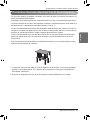
• It should be strong enough (like concrete) to obstruct
the wind from the sea.
• The height and width should be more than 150 % of
the outdoor unit.
• A minimum of 70 cm (27 1/16 inches)
of space between outdoor unit and the windbreak
for easy air flow.
Sea wind Sea wind
Sea wind
Windbreaker/Barrier
Periodic ( more than once/year ) cleaning of the dust or salt particles stuck on the heat exchanger
using water is recommended.
1. Selecting the location(Outdoor Unit)
CAUTION
!

Installation Manual 11
Installation of Indoor, Outdoor Unit
ENGLISH
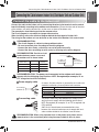
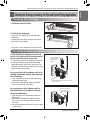
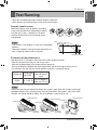
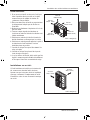
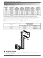
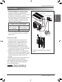
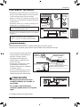
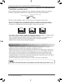
Seasonal Wind And Cautions In Winter
- Sufficient measures are required in a snow area or severe cold area in winter so that product can
be operated well.
- Get ready for seasonal wind or snow in winter even in other areas.
- Install a suction and discharge duct not to let in snow or rain.
- Install the outdoor unit not to come in contact with snow directly. If snow piles up and freezes on the
air suction hole, the system may malfunction. If it is installed at snowy area, attach the hood to the
system.
- Install the outdoor unit at the higher installation console by 50 cm than the average snowfall (annual
average snowfall) if it is installed at the area with much snowfall.
- Where snow accumulated on the upper part of the Outdoor Unit by more than 10 cm, always re-
move snow for operation.
1. The height of H frame must be more than 2 times the snowfall and its width shall not exceed the
width of the product. (If width of the frame is wider than that of the product, snow may accumulate)
2. Don't install the suction hole and discharge hole of the Outdoor Unit facing the seasonal wind.

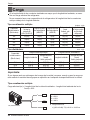
12 Multi Air Conditioner
Installation of Indoor, Outdoor Unit
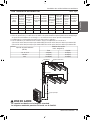
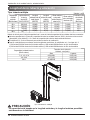
Multi Piping Type
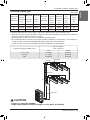
Piping length and elevation
h2
h1
A
B
Multiple Piping Type
Unit : m(ft)
18 k 50(164) 25(82) 3(10) 15(49) 7.5(25) 24 k
24 k 70(230) 25(82) 3(10) 15(49) 7.5(25) 33 k
30 k 75(246) 25(82) 3(10) 15(49) 7.5(25) 40 k
36 k 75(246) 25(82) 3(10) 15(49) 7.5(25) 48 k
Outdoor Unit
Capacity
(Btu/h class)
Max total length
of all pipes
(A+B)/(A+B+C)/
(A+B+C+D)
Max length of
each pipe
(A/B/C/D)
Min length of
each pipe
(A/B/C/D)
Max Elevation
between each
indoor unit and
outdoor unit (h1)
Max elevation
between indoor
units (h2)
Max.Combination
of Indoor unit
(Btu/h class)
Indoor unit Capacity (Btu/h class)
Pipe Diameter
Unit : mm(inch)
Gas Liquid
7, 9, 12, 15 k 9.52(3/8) 6.35(1/4)
18, 24 k 12.7(1/2) 6.35(1/4)
36 k 15.88(5/8) 9.52(3/8)
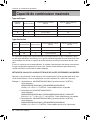
Calculation method for total capacity index = sum up the capacity index of connected indoor units.
Total capacity index = [Sum of all VAHU & Ceiling Concealed Duct (High Static) type indoor units capacity (if
any)] x 1.3 + Sum of all other indoor unit’s capacity
The multiplier(1.3) is only necessary for calculation of combination ratio.
For combinations where it contains one of below conditions, multiplier is 1.2 instead of 1.3. (See example 3)
1) ONE 24 k high static ducted unit/VAHU AND ONE 24 k high static ducted unit/VAHU
2) ONE 24 k high static ducted unit/VAHU AND ONE 36 K high static ducted unit/VAHU
CAUTION
Capacity is based on standard length and maximum allowance length is on the
basis of reliability.
!

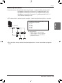
Installation Manual 13
Installation of Indoor, Outdoor Unit
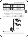
Distributor Piping Type
h1
C
Branch Pipe
Main Pipe
Distributor
Distributor
A
B
h2
Unit : m(ft)
Outdoor Unit
Capacity
(Btu/h class)
Max total length
of all pipes
(Main + Branch
pipes)
Max length
of
Main pipe
(A+B+C)
Max length
of
Branch
pipes
Max length
of each
Branch pipe
Min length of
each pipe
(Main /
Branch
pipes)
Max Elevation
Between each
indoor unit and
outdoor unit
(h1)
Max Eleva-
tion
Between in-
door
(h2)
Max Combi-
nation
of indoor
unit
48 k 145(476) 55(180) 90(295) 15(49) 3(10) 30(98) 15(49) 65 k
54 k 145(476) 55(180) 90(295) 15(49) 3(10) 30(98) 15(49) 73 k
60 k 145(476) 55(180) 90(295) 15(49) 3(10) 30(98) 15(49) 83 k
ENGLISH
Indoor unit Capacity (Btu/h class)
Pipe Diameter
Unit : mm(inch)
Gas Liquid
7, 9, 12, 15 k 9.52(3/8) 6.35(1/4)
18, 24 k 12.7(1/2) 6.35(1/4)
36 k 15.88(5/8) 9.52(3/8)
Calculation method for total capacity index = sum up the capacity index of connected indoor units.
hTotal capacity index = [Sum of all VAHU & Ceiling Concealed Duct (High Static) type indoor units capacity (if
any)] x 1.3 + Sum of all other indoor unit’s capacity
hThe multiplier(1.3) is only necessary for calculation of combination ratio.
hFor combinations where it contains one of below conditions, multiplier is 1.2 instead of 1.3. (See example 3)
1) ONE 24 k high static ducted unit/VAHU AND ONE 24 k high static ducted unit/VAHU
2) ONE 24 k high static ducted unit/VAHU AND ONE 36 K high static ducted unit/VAHU
CAUTION
Capacity is based on standard
length and maximum allowance length is on the basis of reliability.
!

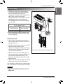
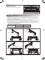
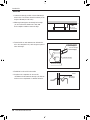
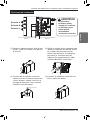
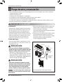
14 Multi Air Conditioner
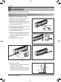
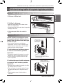
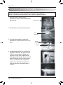
Installation
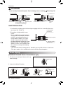
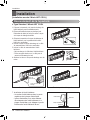
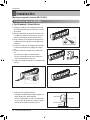
# Standard / Artcool Mirror Type
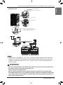
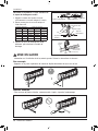
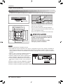
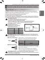
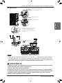
1. Prepare the indoor unit's piping and drain
hose for installation through the wall.
2. Remove the plastic tubing retainer(see the il-
lustration on the right) and pull the tubing and
drain hose away from chassis.
3. Route the indoor tubing and the drain hose to
the required piping hole position.
4. Insert the piping, drain hose, and the connect-
ing cable into the piping hole.
5.
Insert the connecting cable into the indoor unit.
• Don't connect the cable to the indoor unit.
• Make a small loop with the cable for easy
connection later.
6. Tape the tubing and drain hose.
7. Indoor unit installation
• Hang the indoor unit from the hooks at the
top of the installation plate.
• Insert the spacer etc. between the indoor
unit and the installation plate and separate
the bottom of the indoor unit from the wall.
Drain pipe
Connecting
pipe
Tape
Drain hose
Installation plate
Spacer
Indoor unit
80(3 5/32)
For right rear piping For left rear piping
Connecting the piping
[Wall mounted / ART COOL Mirror]
Installation

Installation Manual 15
Installation
ENGLISH
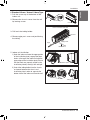
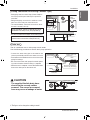
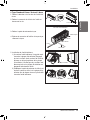
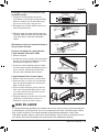
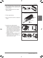
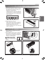
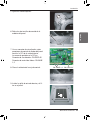
# Standard Libero / Artcool Libero Type
1. Pull the screw cap at the bottom of the
indoor unit
2. Remove the chassis cover from the unit
by loosing screws
3. Pull back the tubing holder.
4. Remove pipe port cover and positioning
the tubing
Chassis cover
Right
Indoor unit back side view
Tubing holder
Backwards
Left
Pipe Port
5. Indoor unit installation
1) Hook the indoor unit onto the upper portion
of the installation plate.( engage the three
hooks at the top of the indoor unit with the
upper edge of the installation plate) Ensure
that the hooks are properly seated on the
installation plate by moving it left and right
2) Unlock the tubing holder from the chassis
and mount between the chassis and
installation plate in order to separate the
bottom side of the indoor unit from the wall
Tubing Holder
Installation plate

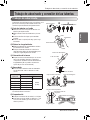
16 Multi Air Conditioner
Installation
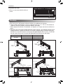
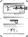
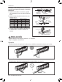
Connecting the piping to the indoor unit
and drain hose to drain pipe.
1. Align the center of the pipes and suffi-
ciently tighten the flare nut by hand.
2. Tighten the flare nut with a wrench.
3. Next, extend the indoor unit's drain hose.
Then attach the drain pipe.
Indoor unit tubing Flare nut Pipes
Wrench
Indoor unit tubing
Open-end wrench (fixed)
Connection pipe
Flare nut
Vinyl tape(narrow)
Adhesive
Drain pipe
Indoor unit drain hose
CAUTION
Installation Information. For left piping. Follow the instruction below.
!
Good case
• Press on the upper side of clamp and unfold the tubing to slowly downward.
Bad case
• Bending the pipe from right to left may cause damage to the tubing.
Outside diameter Torque
mm inch N.m kgf.m lbf.ft
Ø 6.35 1/4 14~18 1.4~1.8 10~13
Ø 9.52 3/8 34~42 3.5~4.3 25~31
Ø 12.7 1/2 49~61 5.0~6.2 36~45
Ø 15.88 5/8 69~82 7.0~8.4 51~60
Ø 19.05 3/4 100~120 10.0~12.2 73~88

Installation Manual 17
Installation
ENGLISH
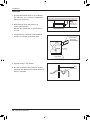
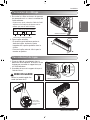
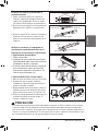
Wrap the insulation material around the con-
necting portion.
1. Overlap the connection pipe insulation and the
indoor unit pipe heat insulation material. Bind
them together with vinyl tape so that there is no
gap.
2. Wrap the area which accommodates the rear
piping housing section with vinyl tape.
3. Bundle the piping and drain hose together by
wrapping them with vinyl tape over the range
within which they fit into the rear piping housing
section.
Reroute the pipings and the drain hose across
the back of the chassis.
Finishing the indoor unit installation
# Standard / Artcool Mirror Type
1. Remove the spacer.
2. Ensure that the hooks are properly seated on
the installation plate by moving it left and right.
3. Press the lower left and right sides of the unit
against the installation plate until the hooks en-
gage into their slots(clicking sound).
# Standard Libero / Artcool Libero Type
1.
Mount the tubing holder in the original positon.
2.
Ensure that the hooks are properly seated on the
installation plate by moving it left and right.
3. Press the lower left and right sides of the unit
against the installation plate until the hooks
engage into their slots (clicking sound).
4.
Finish the assembly by screwing the unit to the
installation plate by using two pieces of type "C"
screws. And assemble a chassis cover.
Plastic bands Insulation material
Vinyl tape(narrow)
Connection pipe
Vinyl tape (wide) Wrap with vinyl tape
Indoor unit pipe
Pipe
Drain hose
Vinyl tape(wide)
Piping for
passage through
piping hole
Drain hose
Connecting
Type 'C' screw
CAUTION
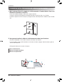
If the split type Indoor unit is installed in a wall having hole or opening near by or back side of the
unit, then the air from other side of the wall can come inside the condition space through that hole /
opening. That air can cause unwanted dew / water droplet formation when it comes in contact with
body of the indoor unit. So all hole or opening on the wall must be blocked very well to avoid water
dropping from the body of the unit.
!

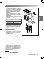
18 Multi Air Conditioner
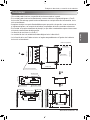
Installation
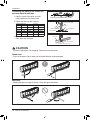
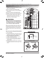
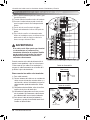
The wall you select should be strong and solid enough to prevent vibration
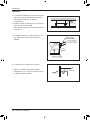
1. Mount the installation plate on the wall with
type "A" screws. If mounting the unit on a concrete wall, use anchor bolts.
• Mount the installation plate horizontally by aligning the centerline using a level.
2. Measure the wall and mark the centerline. It is also important to use caution concerning the lo-
cation of the installation plate-routing of the wiring to power outlets is through the walls typically.
Drilling the hole through the wall for piping connections must be done safely.
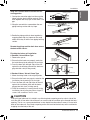
How To Fix
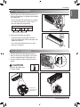
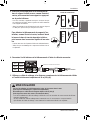
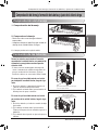
Installation of filters
1) Detach two attached tapes from the plasma
filter.
Plasma Filter
Ø 65
(2 11/20) Ø 65
(2 11/20)
110(4 11/32)
110
(4 11/32)
90
(3 17/32)
70
(2 3/4)
Chassis
Hook
Installation Plate
Type “A”
Left rear piping Right rear piping
Ø 65
(2 11/20)
133(5 1/4)
Ø 65
(2 11/20)
100(3 15/16)
Chassis
Hook
Installation Plate
Type “A”
Left rear piping Right rear piping
Ø 65
(2 11/20)
133(5 1/4)
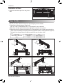
95(5 3/4)
217(8 17/32)
175(6 7/8)
442(17 13/32) 442(17 13/32)
Ø 65
(2 11/20)
Installation Plate
Chassis
Hook
Type "A" Screws
Right rear piping
Left rear piping Installation Plate
Place a level on raised tab
Unit Outline
Ø 65
(2 11/20)
Ø 65
(2 11/20)
69(2 23/32)
56(2 7/32)
207(8 5/32)
105(4 1/8)
460(18 1/8) 570(22 7/16)
Installation Plate
Chassis
Hook
Type "A" Screws
Left rear piping
Installation Plate
Place a level on raised tab
Unit Outline
Right
rear
piping
Measuring Tape
Hanger
Measuring Tape
<Type 1> <Type 2>
<Type 3> <Type 4>
Indoor Type Capacity (kBtu/h) Type
Wall mounted / ART COOL
Mirror
7/9/12/15 Type 1 / Type 3
18/24 Type 2 / Type 4

Installation Manual 19
Installation
ENGLISH
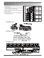
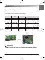
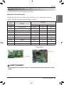
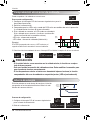
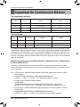
1. Connect the wires to the terminals on the con-
trol board individually according to the outdoor
unit connection.
• Ensure that the color of the wires of outdoor
unit and the terminal No. are the same as
those of indoor unit respectively.
2. Attach the Grille onto the cabinet.
• Grasp the lower left and right side of the
Grille and engage four tabs on the top inside
edge of the chassis.
• Press the Grille toward the chassis until it
goes back into place.
Connecting cable
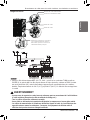
Conduit connection
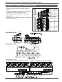
1. Set the connecting cable into the terminal
block of indoor unit, and tighten set screw to
lock the conduit bracket to the indoor unit.
2. Join the conduit and the conduit bracket to-
gether.
Connecting cable
Lock nut
Conduit
Conduit
bracket
Terminal Block in Indoor
1(L1) 2(L2) 3 4
Connected to Outdoor Unit
View
Terminal block
Connecting cable
Cable retainer
CAUTION
Must use the elbow type
(L-Type) conduit.
!
Wiring Connection

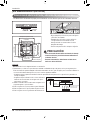
20 Multi Air Conditioner
Installation
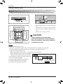
[Ceiling Cassette Type]
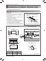
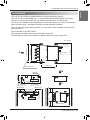
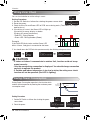
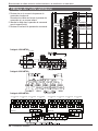
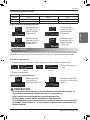
Ceiling dimension and hanging bolt location
Level gauge
Ceiling
Ceiling board
Unit: mm(inch)
585~660(23 1/16~26) (Ceiling Opening)
517(20 3/8)
461(18 5/32)
517(20 3/8)
585~660(23 1/16~26) (Ceiling Opening)
523(20 19/32)
570(22 15/32)
Unit Size
570(22 15/32)
Unit Size
319(12 9/16)
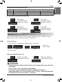
• The dimensions of the paper model for installation are the same as those of the ceiling opening dimensions.
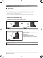
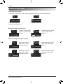
• Avoid the following installation location.
1. Such places as restaurants and kitchen where considerable amount of oil steam and flour is generated.
These may cause heat exchange efficiency reduction, or water drops, drain pump mal-function.
In these cases, take the following actions;
• Make sure that ventilation fan is enough to cover all noxious gases from this place.
• Ensure enough distance from the cooking room to install the air
conditioner in such a place where it may not suck oily steam.
2. Avoid installing air conditioner in such places where cook-
ing oil or iron powder is generated.
3. Avoid places where inflammable gas is generated.
4. Avoid place where noxious gas is generated.
5. Avoid places near high frequency generators.
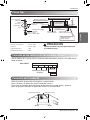
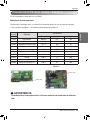
NOTICE
CAUTION
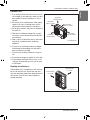
• This air-conditioner uses a drain pump.
• Install the unit horizontally using a level gauge.
• During the installation, care should be taken not
to damage electric wires.
!
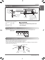
• Select and mark the position for fixing bolts and piping
hole.
• Decide the position for fixing bolts slightly tilted to the
drain direction after considering the direction of drain
hose.
• Drill the hole for anchor bolt on the wall.
Use the ventilation fan
for smoke-collecting
hood with sufficient
capacity.
Cooking table
Air conditioner
Take enough
distance
La page est en cours de chargement...
La page est en cours de chargement...
La page est en cours de chargement...
La page est en cours de chargement...
La page est en cours de chargement...
La page est en cours de chargement...
La page est en cours de chargement...
La page est en cours de chargement...
La page est en cours de chargement...
La page est en cours de chargement...
La page est en cours de chargement...
La page est en cours de chargement...
La page est en cours de chargement...
La page est en cours de chargement...
La page est en cours de chargement...
La page est en cours de chargement...
La page est en cours de chargement...
La page est en cours de chargement...
La page est en cours de chargement...
La page est en cours de chargement...
La page est en cours de chargement...
La page est en cours de chargement...
La page est en cours de chargement...
La page est en cours de chargement...
La page est en cours de chargement...
La page est en cours de chargement...
La page est en cours de chargement...
La page est en cours de chargement...
La page est en cours de chargement...
La page est en cours de chargement...
La page est en cours de chargement...
La page est en cours de chargement...
La page est en cours de chargement...
La page est en cours de chargement...
La page est en cours de chargement...
La page est en cours de chargement...
La page est en cours de chargement...
La page est en cours de chargement...
La page est en cours de chargement...
La page est en cours de chargement...
La page est en cours de chargement...
La page est en cours de chargement...
La page est en cours de chargement...
La page est en cours de chargement...
La page est en cours de chargement...
La page est en cours de chargement...
La page est en cours de chargement...
La page est en cours de chargement...
La page est en cours de chargement...
La page est en cours de chargement...
La page est en cours de chargement...
La page est en cours de chargement...
La page est en cours de chargement...
La page est en cours de chargement...
La page est en cours de chargement...
La page est en cours de chargement...
La page est en cours de chargement...
La page est en cours de chargement...
La page est en cours de chargement...
La page est en cours de chargement...
La page est en cours de chargement...
La page est en cours de chargement...
La page est en cours de chargement...
La page est en cours de chargement...
La page est en cours de chargement...
La page est en cours de chargement...
La page est en cours de chargement...
La page est en cours de chargement...
La page est en cours de chargement...
La page est en cours de chargement...
La page est en cours de chargement...
La page est en cours de chargement...
La page est en cours de chargement...
La page est en cours de chargement...
La page est en cours de chargement...
La page est en cours de chargement...
La page est en cours de chargement...
La page est en cours de chargement...
La page est en cours de chargement...
La page est en cours de chargement...
La page est en cours de chargement...
La page est en cours de chargement...
La page est en cours de chargement...
La page est en cours de chargement...
La page est en cours de chargement...
La page est en cours de chargement...
La page est en cours de chargement...
La page est en cours de chargement...
La page est en cours de chargement...
La page est en cours de chargement...
La page est en cours de chargement...
La page est en cours de chargement...
La page est en cours de chargement...
La page est en cours de chargement...
La page est en cours de chargement...
La page est en cours de chargement...
La page est en cours de chargement...
La page est en cours de chargement...
La page est en cours de chargement...
La page est en cours de chargement...
La page est en cours de chargement...
La page est en cours de chargement...
La page est en cours de chargement...
La page est en cours de chargement...
La page est en cours de chargement...
La page est en cours de chargement...
La page est en cours de chargement...
La page est en cours de chargement...
La page est en cours de chargement...
La page est en cours de chargement...
La page est en cours de chargement...
La page est en cours de chargement...
La page est en cours de chargement...
La page est en cours de chargement...
La page est en cours de chargement...
La page est en cours de chargement...
La page est en cours de chargement...
La page est en cours de chargement...
La page est en cours de chargement...
La page est en cours de chargement...
La page est en cours de chargement...
La page est en cours de chargement...
La page est en cours de chargement...
La page est en cours de chargement...
La page est en cours de chargement...
La page est en cours de chargement...
La page est en cours de chargement...
La page est en cours de chargement...
La page est en cours de chargement...
La page est en cours de chargement...
La page est en cours de chargement...
La page est en cours de chargement...
La page est en cours de chargement...
La page est en cours de chargement...
La page est en cours de chargement...
La page est en cours de chargement...
La page est en cours de chargement...
La page est en cours de chargement...
La page est en cours de chargement...
La page est en cours de chargement...
La page est en cours de chargement...
La page est en cours de chargement...
La page est en cours de chargement...
-
 1
1
-
 2
2
-
 3
3
-
 4
4
-
 5
5
-
 6
6
-
 7
7
-
 8
8
-
 9
9
-
 10
10
-
 11
11
-
 12
12
-
 13
13
-
 14
14
-
 15
15
-
 16
16
-
 17
17
-
 18
18
-
 19
19
-
 20
20
-
 21
21
-
 22
22
-
 23
23
-
 24
24
-
 25
25
-
 26
26
-
 27
27
-
 28
28
-
 29
29
-
 30
30
-
 31
31
-
 32
32
-
 33
33
-
 34
34
-
 35
35
-
 36
36
-
 37
37
-
 38
38
-
 39
39
-
 40
40
-
 41
41
-
 42
42
-
 43
43
-
 44
44
-
 45
45
-
 46
46
-
 47
47
-
 48
48
-
 49
49
-
 50
50
-
 51
51
-
 52
52
-
 53
53
-
 54
54
-
 55
55
-
 56
56
-
 57
57
-
 58
58
-
 59
59
-
 60
60
-
 61
61
-
 62
62
-
 63
63
-
 64
64
-
 65
65
-
 66
66
-
 67
67
-
 68
68
-
 69
69
-
 70
70
-
 71
71
-
 72
72
-
 73
73
-
 74
74
-
 75
75
-
 76
76
-
 77
77
-
 78
78
-
 79
79
-
 80
80
-
 81
81
-
 82
82
-
 83
83
-
 84
84
-
 85
85
-
 86
86
-
 87
87
-
 88
88
-
 89
89
-
 90
90
-
 91
91
-
 92
92
-
 93
93
-
 94
94
-
 95
95
-
 96
96
-
 97
97
-
 98
98
-
 99
99
-
 100
100
-
 101
101
-
 102
102
-
 103
103
-
 104
104
-
 105
105
-
 106
106
-
 107
107
-
 108
108
-
 109
109
-
 110
110
-
 111
111
-
 112
112
-
 113
113
-
 114
114
-
 115
115
-
 116
116
-
 117
117
-
 118
118
-
 119
119
-
 120
120
-
 121
121
-
 122
122
-
 123
123
-
 124
124
-
 125
125
-
 126
126
-
 127
127
-
 128
128
-
 129
129
-
 130
130
-
 131
131
-
 132
132
-
 133
133
-
 134
134
-
 135
135
-
 136
136
-
 137
137
-
 138
138
-
 139
139
-
 140
140
-
 141
141
-
 142
142
-
 143
143
-
 144
144
-
 145
145
-
 146
146
-
 147
147
-
 148
148
-
 149
149
-
 150
150
-
 151
151
-
 152
152
-
 153
153
-
 154
154
-
 155
155
-
 156
156
-
 157
157
-
 158
158
-
 159
159
-
 160
160
-
 161
161
-
 162
162
-
 163
163


LG LMU363HV Mode d'emploi
- Catégorie
- Climatiseurs split-system
- Taper
- Mode d'emploi
dans d''autres langues
- English: LG LMU363HV Operating instructions
- español: LG LMU363HV Instrucciones de operación