
DANBY PRODUCTS LIMITED, ONTARIO, CANADA N1H 6Z9
DANBY PRODUCTS INC., FINDLAY, OHIO, USA 45840
OWNER’S MANUAL
MANUEL DU PROPRIÉTAIRE
MANUAL DEL PROPIETARIO
www.Danby.com
THROUGH-THE-WALL AIR CONDITIONER
Owner’s Manual.............................1 - 11
CLIMATISEUR MURAL
Manual du propriétaire.................12 - 22
AIRE ACONDICIONADO DE PARED
Manual del propietario..................23 - 33
2019.12.11
MODEL • MODÈLE • MODELO
DPTA090HEB1WDB
DPTA120HEB1WDB
DPTA150HEB1WDB

Welcome
Welcome to the Danby family. We are proud of our quality products and we believe in
dependable service. We suggest that you read this owner’s manual before plugging in your new
appliance as it contains important operation information, safety information, troubleshooting and
maintenance tips to ensure the reliability and longevity of your appliance.
Visit www.Danby.com to access self service tools, FAQs and much more. For additional assistance
call 1-800-263-2629.
Note the information below; you will need this information to obtain service under warranty.
You must provide the original purchase receipt to validate your warranty and receive service.
Model Number: _________________________________________________
Serial Number: _________________________________________________
Date of Purchase: _______________________________________________
Need Help?
Before you call for service, here are a few things you can do to help us serve you better.
Read this owner’s manual:
It contains instructions to help you use and maintain your appliance properly.
If you receive a damaged appliance:
Immediately contact the retailer or builder that sold you the appliance.
Save time and money:
Check the troubleshooting section at the end of this manual before calling. This section
will help you solve common problems that may occur.
1-800-26- Danby
(1-800-263-2629)
1

Important Safety Information
READ AND FOLLOW ALL SAFETY INSTRUCTIONS
SAVE THESE INSTRUCTIONS!
ELECTRICAL REQUIREMENTS
All wiring must comply with local and national
codes and must be installed by a qualifi ed
electrician. Check the available power supply and
resolve any wiring problems before installing and
operating this appliance.
This 230 V appliance may be used in any properly
wired, general purpose household receptacle.
The rating plate located on the right side of the
appliance just above the power cord contains
electrical and other technical data.
SAFETY INSTRUCTIONS
This appliance is not intended for use by persons,
including children, with reduced physical, sensory
or mental capabilities or lack of experience and
knowledge, unless they have been given supervision
or instruction concerning use of the appliance by a
person responsible for their safety.
Children should be supervised to ensure that they
do not play with the appliance.
Do not install the appliance where leakage of
combustible gas is suspected.
POWER CORD INSTRUCTIONS
The power supply cord contains a current device
that senses damage to the power cord. To test the
power supply cord:
1. Press the TEST button on the power supply cord.
The RESET button will click and pop out.
2. Press the RESET button until it clicks into place.
3. The power supply cord is now supplying
electricity to the appliance.
Do not use this device to turn the appliance on or
off. Ensure that the RESET button is pushed in for
correct operation. The power supply cord must be
replaced if it fails to reset when the TEST button is
pushed.
2
GROUNDING INSTRUCTIONS
This appliance must be grounded. Grounding
reduces the risk of electrical shock by providing an
escape wire for the electrical current.
This appliance has a cord that has a grounding
wire with a 3-prong plug. The power cord must be
plugged into an outlet that is properly grounded.
If the outlet is a 2-prong wall outlet, it must be
replaced with a properly grounded 3-prong wall
outlet.
WARNING - Improper use of the grounding
plug can result in a risk of electric shock.
Consult a qualifi ed electrician or service agent
if the grounding instructions are not completely
understood, or if doubt exists as to whether the
appliance is properly grounded.
Do not connect your appliance to extension
cords or together with another appliance in the
same wall outlet. Do not splice the power cord.
Do not under any circumstances cut or remove the
third ground prong from the power cord. Do not
use extension cords or ungrounded (two prongs)
adapters.
If the power supply cord is damaged, it must be
replaced by the manufacturer, its service agent or
similar qualifi ed person in order to avoid hazard.

INSTALLATION INSTRUCTIONS
3
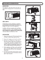
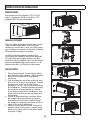
DIMENSIONS
This appliance is 42 inches (106.7 cm) wide, 16
inches (40.8 cm) high and 23.9 inches (60.6 cm)
deep.
WALL SLEEVE
All wall sleeves used to install the air conditioner
must be in good structural condition and have a
rear grille that securely attaches to the sleeve or the
fl ange of the sleeve to secure the appliance.
Install the wall sleeve according to the wall sleeve
installation instructions. When installing the sleeve
make certain there is nothing within 20 inches (50.8
cm) of the back of the appliance that would interfere
with heat radiation and exhaust air fl ow.
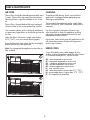
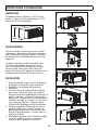
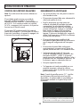
INSTALLATION
1. Remove the front panel. Pull out from the bottom
to release it from the tabs and then lift up.
2. Remove the shipping screw from the vent door.
3. Rotate the vent control lever to either open or
close the vent door. When the vent control lever
is set to “close”, only the air inside the room is
circulated. When the vent control lever is set to
“open”, outdoor air will be drawn into the room.
This can reduce heating or cooling effi ciency.
4. Lift the appliance and slide it into the wall sleeve
until it is set fi rmly against the front wall of the
sleeve and secure with four screws through the
fl ange holes.
5. Reinstall the front panel. Place the tabs over the
top rail and push inward at the bottom until the
panel snaps into place.
1
2
3
4
4
5

INSTALLATION INSTRUCTIONS
4
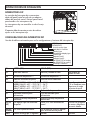
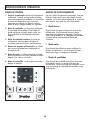
DIP SWITCHES
Dip switch controls are located behind the front
panel through an opening below the control panel.
Remove the front panel to access the dip switches.
Dip switches are accessible without opening the
control box.
The appliance should be unplugged before making
adjustments to the dip switches.
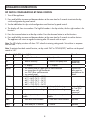
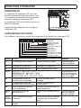
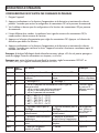
DIP SWITCH CONFIGURATIONS
See the table below for dip switch confi gurations and functions.
UP(ON)
DOWN(OFF)
1 2 3 4 1 2 3 4
S
1
S2
S
3
S
4
S5
S6
S7
S8
X
S
9
A0-
A3
1 2 1 2 3 4
S11
Wall thermostat type
Load delay for 3 seconds
Heating type
Temperature display type
Control type
Setpoint limit 1
Setpoint limit 2
Fan CON/CYC for heating
Fan CON/CYC for cooling
Low temp. Protection
Number UP (ON) DOWN (OFF) Remarks
S1 Electric heat only Electric and pump heat Heat pump model
only
S2 Temperature display °F Temperature display °C
S3 Wall thermostat enable Control panel enable
S4*S5 UP*UP: 61°F ~ 86°F (16°C ~ 30°C)
UP*DOWN: 65°F ~ 78°F (18°C ~ 26°C)
DOWN*UP: 63°F ~ 80°F (17°C ~ 27°C)
DOWN*DOWN: 68°F ~ 75°F (20°C ~ 24°C)
Confi guration of S4
and S5 combine to
select set point range
S6 Fan continuous run for heating Fan cycle for heating
S7 Fan continuous run for cooling Fan cycle for cooling
S8 Low temperature protection enable Low temperature protection disable
S9 (S3
UP)
Use some types of wall thermostat Use PTAC other wall thermostat Consult with
sales agent or
manufacturer for
details
S9 (S3
DOWN)
Use control panel only Use control panel or some types of
wall thermostat
Sw11 Load delay for 3 seconds Normal Optional

5
INSTALLATION INSTRUCTIONS
DIP SWITCH CONFIGURATIONS BY PANEL CONTROL
1. Turn off the appliance.
2. Press and hold the increase and decrease buttons at the same time for 3 seconds to activate the dip
switch confi guration by panel control.
3. See the table below for dip switch confi gurations and functions by panel control.
4. The display will show two numbers. The high left number is for dip switches, the low right number is for
functions.
5. Press the increase button to set the dip switches. Press the decrease button to set the functions.
6. Press and hold the increase and decrease buttons at the same time for 3 seconds to confi rm choices.
The appliance will return to regular functioning after 30 seconds with no input.
Note: The LED display window will show “00” when fi rst entering setting mode. Set switches in sequence
one at a time.
Note: To activate front desk control function, set dip switch SW7 to “DOWN(OFF)” and then set the panel
control to “A0”.
Number High (left) Low (right) Remarks
/ 0 1 - by panel control 0 - by dip switches
S1 1 1 - electric heat only 0 - electric and pump heat Heat pump
model only
S2 2 1 - °F display 0 - °C display
S3*S9 3 3 - use control panel or some types of wall thermostat
2 - use some types of wall thermostat
1 - use PTAC other wall thermostat
0 - use control panel
Consult with
sales agent or
manufacturer for
details
S4*S5 4 4 - 62°F ~ 86°F (17°C ~ 30°C)
3 - 61°F ~ 86°F (16°C ~ 30°C)
2 - 65°F ~ 78°F (18°C ~ 26°C)
1 - 63°F ~ 80°F (17°C ~ 27°C)
0 - 68°F ~ 75°F (20°C ~ 24°C)
S6 6 1 - continuous fan for heating 0 - fan cycle for heating Not available
for “use PTAC
other wall
thermostat”
S7 7 1 - continuous fan for cooling 0 - fan cycle for cooling
S8 8 1 - low temperature protection
enable
0 - low temperature protection
disable
Optional
SW7 A 1 - front desk control enable 0 - front desk control disable Optional
Sw11 B 1 - load delay for 3 seconds 0 - normal Optional

6
INSTALLATION INSTRUCTIONS
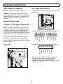
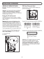
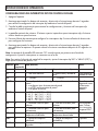
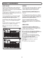
WALL THERMOSTAT TERMINAL
Note: Using a wall thermostat is optional.
Important: Only trained, qualifi ed personnel
should access the electrical panel on the appliance
and install electrical accessories. Contact a local
electrical contractor, dealer or distributor for
assistance.
Thermostat Wire Routing
Thermostat wire is fi eld supplied. Recommended
wire gauge is 18 to 20 gauge solid thermostat wire.
Note: It is recommended that extra wires are run
to the appliance in case any are damaged during
installation. Thermostat wire should always be
routed around or under, never through the wall
sleeve. The wire should be routed behind the front
panel to the easily accessible terminal connector.
Pull the dip switch to the DOWN(OFF) position.
Insert the wire connector of the wall thermostat
into the relevant terminal according to the different
shapes as shown.
A: Dip switch
B: Terminal
A
B
B
PTAC Other Wall Thermostat
Remove the two screws as shown and take the cover
panel down.
Terminal of PTAC other wall thermostat (MODE A)
FC(L)
FC(N)
LOW-FAN
HI-FAN
4-WAY
HEAT2
HEAT1
COMP
24V(N)
24V(L)
Terminal of PTAC other wall thermostat (MODE B)
LOW-FAN
HI-FAN
4-WAY
HEAT1
COMP
24V(L)
24V(N)
Caution: Failure to follow this caution may result
in equipment damage or improper operation.
Improper wiring may damage the electronics.
Common busing is not permitted. Damage or erratic
operation may result.

FRONT DESK CONTROL
Note: Using the front desk control is optional.
The controller can handle a switch signal from
FC(L) and FC(N) input, called front desk control.
Input must be 24VAC. If the system does not receive
a 24VAC signal it will turn off; otherwise the
appliance runs in normal control.
The dip switch can control the front desk control
feature. If the dip switch is in the down position,
the appliance will turn off, otherwise it will run as
normal.
ADDITIONAL REQUIREMENTS
• Use 4-way terminal for heat pump connection
only.
• Wall thermostat must be heating changeover
4-way valve.
• For thermostats that have only one fan speed
output (on or auto) the fan speed is determined
by how the terminal connector is wired. If
low fan is desired, wire the G output from the
thermostat to (LOW-FAN) on the appliance’s
terminal block. If high fan is desired, wire the
G output from the thermostat to (HI-FAN) on the
appliance’s terminal block.
• The range of set temperature of wall thermostat
must be in consonance with the range of dip
switch setting.
• Wall thermostat must be set the type properly in
consonance with the appliance type; heat pump
or no heat pump.
• If the wall thermostat has only one electrical
heater output, connect the two terminals of
HEAT 1 and HEAT 2, the appliance can operate
two electrical heaters (only if the appliance has
two electrical heaters). Otherwise operate one
electrical heater.
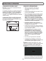
• Do not remove the control panel.
• If the appliance is being controlled by a wall
mounted thermostat, place the provided cover
over the control panel as per the below.
Note: When the display shows “LC” it means the
buttons on the control panel are not available and
the appliance should be controlled by the wall
mounted thermostat that it is connected to.
INSTALLATION INSTRUCTIONS
7
Cette unité est contrôlée par un thermostat mural
This unit is controlled by a wall mounted thermostat

8
OPERATING INSTRUCTIONS
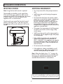
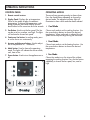
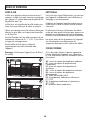
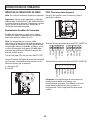
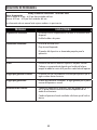
CONTROL PANEL
1. Remote control receiver
2. Display Panel: Displays the set temperature.
When in fan mode, displays the ambient
temperature. To change the temperature scale
being displayed, press and hold the up and
down buttons at the same time for three seconds.
3. Fan Button: Used to set the fan speed. The fan
can be set to low, medium, and high. The lights
will indicate the chosen fan speed.
4. Continuous fan button: In cooling mode, press
to set the fan to run continuously.
5. Increase and decrease buttons: Used to adjust
the set temperature in 1° increments.
6. Mode button: Used to choose the operating
mode. The lights will indicate the chosen mode,
cool, heat or fan.
7. Power button: Used to turn the appliance on or
off.
2
4 7
3
5
6
1
OPERATING MODES
There are three operating modes to choose from.
Press the Mode Button repeatedly to choose the
desired mode. The adjacent indicator light will
illuminate to show which mode has been selected.
• Cool Mode
Choose cool mode to set the cooling function. Use
the up and down buttons to choose the desired
temperature. When cool mode is selected, the fan
speed can be adjusted by pressing the fan button.
• Heat Mode
Choose heat mode to set the heating function. Use
the up and down buttons to choose the desired
temperature.
• Fan Mode
Choose fan mode to run the internal fan without
engaging the cooling function. Press the fan button
repeatedly to choose the fan speed, low, med or
high.

9
AIR FILTER
The air fi lter should be cleaned approximately every
2 weeks. The air fi lter may require more frequent
cleaning if there is signifi cant dander or fur in the
air.
The air fi lter is located behind the front intake grill.
Grasp the fi lter by the center and pull up and out.
Use a vacuum cleaner with a soft brush attachment
to remove any large debris or dust build up from the
air fi lter.
Wash the fi lter in lukewarm, soapy water, below
40°C (104°F), or use a neutral cleaning agent.
Rinse the fi lter with clean water and dry thoroughly
before reinstalling in the appliance.
Note: Do not operate the appliance without the air
fi lter installed.
CARE & MAINTENANCE
CLEANING
To avoid possible electric shock, ensure that the
appliance is unplugged before performing any
cleaning or maintenance.
The outside of the appliance can be wiped clean
with a soft cloth or with a lukewarm, damp cloth if
necessary.
Do not use gasoline, benzene, thinner or any
other chemicals to clean this appliance as these
substances can cause damage to the fi nish and
deformation of plastic parts.
Never pour water directly onto the appliance as this
will cause deterioration of electrical components
and wiring insulation.
ERROR CODES
If any of the below error codes appear on the
display, unplug the appliance and then plug it back
in. If the error code persists, call for service.
AS - room temperature sensor error
ES - evaporator temperature sensor error
CS - condenser temperature sensor error
OS - outside temperature sensor error
HS - exhaust temperature sensor error
LE - wire controller error
LO - room temperature is lower than 0°C / 32°F
HI - room temperature is higher than 37°C / 99°F
FP - low temperature protection
1
2

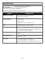
TROUBLESHOOTING
Danby Consumer Care: 1-800-263-2629
Hours of operation:
Monday to Thursday 8:30 am - 6:00 pm Eastern Standard Time
Friday 8:30 am - 4:00 pm Eastern Standard Time
Information in this manual is subject to change without notice.
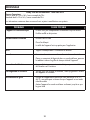
PROBLEM POSSIBLE CAUSE
Appliance will not operate • Plug is not fully inserted into the wall outlet
• Blown fuse or circuit breaker
Insuffi cient cooling • Air fi lter is dirty
• Blocked air fl ow
• Appliance size is too small for application
Noise • Inadequate support in window installation
Odors • Formation of mold or mildew on internal wet surfaces
• Place an algaecide tablet in base pan; push the tablet through
the grill on either side of the appliance
Water dripping inside • Appliance is not properly angled to allow water to drain to the
outside
Water dripping outside • On very hot or humid days dripping water from the back of the
appliance is normal
Frost build up • When outdoor temperatures are below 18.3°C (65°F) frost may
form when the appliance is in cooling mode
• Switch the appliance to fan only mode until the frost melts
10

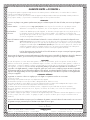
LIMITED IN-HOME APPLIANCE WARRANTY
This quality product is warranted to be free from manufacturer’s defects in material and workmanship, provided that the unit is used under the normal operating
conditions intended by the manufacturer.
This warranty is available only to the person to whom the unit was originally sold by Danby Products Limited (Canada) or Danby Products Inc. (U.S.A.) (hereafter
“Danby”) or by an authorized distributor of Danby, and is non-transferable.
TERMS OF WARRANTY
Plastic parts, are warranted for thirty (30) days only from purchase date, with no extensions provided.
First Year
During the rst twelve (12) months, any functional parts of this product found to be defective, will be repaired or replaced, at warrantor’s
option, at no charge to the ORIGINAL purchaser.
To obtain
Danby reserves the right to limit the boundaries of “In Home Service” to the proximity of an Authorized Service Depot. Any app liance
Service
requiring service outside the limited boundaries of “In Home Service” , it will be the consumer’s responsibility to transport the appliance (at
their own expense) to the original retailer (point of purchase) or a service depot for repair. See “Boundaries of In Home Serv ice” below.
Contact your dealer from whom your unit was purchased, or contact your nearest authorized Danby service depot, where service
must be performed by a qualied service technician.
If service is performed on the units by anyone other than an authorized service depot, or the unit is used for commercial appli cation, all
obligations of Danby under this warranty shall be void.
Boundaries of
If the appliance is installed in a location that is 100 kilometers (62 miles) or more from the nearest service center your unit must be
In Home Service
delivered to the nearest authorized Danby Service Depot, as service must only be performed by a technician qualied and certif ied for
warranty service by Danby. Transportation charges to and from the service location are not protected by this warranty and are t he
responsibility of the purchaser.
Nothing within this warranty shall imply that Danby will be responsible or liable for any spoilage or damage to food or other c ontents of this appliance, whether due
to any defect of the appliance, or its use, whether proper or improper.
EXCLUSIONS
Save as herein provided, Danby, there are no other warranties, conditions, representations or guarantees, express or implied, m ade or intended by Danby or its
authorized distributors and all other warranties, conditions, representations or guarantees, including any warranties, conditio ns, representations or guarantees
under any Sale of Goods Act or like legislation or statue is hereby expressly excluded. Save as herein provided, Danby shall no t be responsible for any damages
to persons or property, including the unit itself, howsoever caused or any consequential damages arising from the malfunction o f the unit and by the purchase of
the unit, the purchaser does hereby agree to indemnify and hold harmless Danby from any claim for damages to persons or propert y caused by the unit.
GENERAL PROVISIONS
No warranty or insurance herein contained or set out shall apply when damage or repair is caused by any of the following:
1) Power failure.
2) Damage in transit or when moving the appliance.
3) Improper power supply such as low voltage, defective house wiring or inadequate fuses.
4) Accident, alteration, abuse or misuse of the appliance such as inadequate air circulation in the room or abnormal operating con ditions
(extremely high or low room temperature).
5) Use for commercial or industrial purposes (ie. If the appliance is not installed in a domestic residence).
6) Fire, water damage, theft, war, riot, hostility, acts of God such as hurricanes, oods etc.
7) Service calls resulting in customer education.
8) Improper Installation (ie. Building-in of a free standing appliance or using an appliance outdoors that is not approved for out door application).
Proof of purchase date will be required for warranty claims; so, please retain bills of sale. In the event warranty service is required, present this document to our
AUTHORIZED SERVICE DEPOT.
Danby Products Limited
PO Box 1778, Guelph, Ontario, Canada N1H 6Z9
Telephone: (519) 837-0920 FAX: (519) 837-0449
Danby Products Inc.
PO Box 669, Findlay, Ohio, U.S.A. 45840
Telephone: (419) 425-8627 FAX: (419) 425-8629
04/09
1-800-263-2629
Warranty Service
In-home
Danby reserves the right to limit the boundaries of “In Home Service” to the proximity of an authorized service
depot. Any appliance requiring service outside the limited boundaries of “In Home Service”, will be the consumer’s
responsibility to transport at their own expense to the original point of purchase or a service depot for repair. If the
appliance is installed in a location that is 100 kilometers (62 miles) or more from the nearest service center, it must
be delivered to the nearest authorized Danby Service Depot by the purchaser.
Transportation charges to and from the service location are not protected by this warranty and are the
responsibility of the purchaser.
During the first twenty four (24) months, any functional parts of this product found to be defective, will be repaired
or replaced, at warrantor’s option, at no charge to the original purchaser.
Contact the dealer where the unit was purchased, or contact the nearest authorized Danby service depot, where
service must be performed by a qualified service technician. If service is performed on the unit by anyone other
than an authorized service depot, all obligations of Danby under this warranty shall be void.
First 24 months
To obtain service
Boundaries of
in-home service
LIMITED “IN HOME” WARRANTY
This quality product is warranted to be free from manufacturer’s defects in material and workmanship, provided that the unit is used
under the normal operating conditions intended by the manufacturer.
This warranty is available only to the person to whom the unit was originally sold by Danby Products Limited (Canada) or Danby
Products Inc. (U.S.A.) (hereafter “Danby”) or by an authorized distributor of Danby, and is non-transferable.
TERMS OF WARRANTY
Plastic parts are warranted for thirty (30) days from the date of purchase, with no extensions provided.
Nothing within this warranty shall imply that Danby will be responsible or liable for any spoilage or damage to food or other
contents of this appliance, whether due to any defect of the appliance, or its use, whether proper or improper.
EXCLUSIONS
Save as herein provided, by Danby, there are no other warranties, conditions, representations or guarantees, express or implied, made
or intended by Danby or its authorized distributors and all other warranties, conditions, representations or guarantees, including any
warranties, conditions, representations or guarantees under any Sale of Goods Act or like legislation or statute is hereby expressly
excluded. Save as herein provided, Danby shall not be responsible for any damages to persons or property, including the unit itself,
howsoever caused or any consequential damages arising from the malfunction of the unit and by the purchase of the unit, the
purchaser does hereby agree to indemnify and hold harmless Danby from any claim for damages to persons or property caused by
the unit.
GENERAL PROVISIONS
No warranty or insurance herein contained or set out shall apply when damage or repair is caused by any of the following:
1) Power failure.
2) Damage in transit or when moving the appliance.
3) Improper power supply such as low voltage, defective house wiring or inadequate fuses.
4) Accident, alteration, abuse or misuse of the appliance such as inadequate air circulation in the room or abnormal operating
conditions (ie. extremely high or low room temperature).
5) Use for commercial or industrial purposes (ie. If the appliance is not installed in a domestic residence).
6) Fire, water damage, theft, war, riot, hostility, acts of God such as hurricanes, floods etc.
7) Service calls resulting in customer education.
8) Improper Installation (ie. Building-in of a free standing appliance or using an appliance outdoors that is not approved for outdoor
application, including but not limited to: garages, patios, porches or anywhere that is not properly insulated or climate controlled).
Proof of purchase date will be required for warranty claims; retain bills of sale. In the event that warranty service is required, present
the proof of purchase to our authorized service depot.
Warranty Service
In Home
Danby Products Limited
PO Box 1778, Guelph, Ontario, Canada N1H 6Z9
Telephone: (519) 837-0920 FAX: (519) 837-0449
Danby Products Inc.
PO Box 669, Findlay, Ohio, U.S.A. 45840
Telephone: (419) 425-8627 FAX: (419) 425-8629
1-800-263-2629
04/17

12
Bienvenue
Bienvenue à la famille Danby. Nous sommes fi ers de la qualité de nos produits et nous croyons
en le service fi able. Nous vous suggérons de lire ce manual d’utilisation avant de brancher
votre nouvel appareil car il contient des informations inportantes sur l’utilisation, la sécurité, le
dépannage et la maintenance, afi n d’assurer la fi abilité et la longévité de votre appareil.
Visitez www.Danby.com pour accéder aux outils d’autoservice, aux FAQ et bien plus encore. Pour
obtenir de l’aide supplémentaire, composez 1-800-263-2629.
Notez les informations ci-dessous; Vous aurez besoin de cette information pour obtenir un
service sous garantie.
Vous devez fournir le reçu d’achat original pour valider votre garantie et recevoir le service.
Numéro de modèle: _____________________________________________
Numéro de serie: _______________________________________________
Date d’achat: __________________________________________________
Besoin d’assistance?
Avant d’appeler pour service, voici quelques choses que vous pouvez faire pour nous
aider à mieux vous servir.
Lire ce manuel du propriétaire:
Il contient des instructions pour vous aider à utiliser et à maintenir votre appareil
correctement.
Si vous recevez un appareil endommagé:
Contactez immédiatement le revendeur ou l’entrepreneur qui vous a vendu l’appareil.
Gagnez du temps et de l’argent:
Avant d’appeler pour service, consultez la section de dépannage à la fi n de ce manuel.
Cette section vous aidera à résoudre les problèmes courants pouvant survenir.
1-800-26- Danby
(1-800-263-2629)

Informations importantes de sécurité
LIRE ET SUIVRE TOUTES LES INSTRUCTIONS DE SÉCURITÉ
13
GARDEZ CES INSTRUCTIONS!
EXIGENCES ÉLECTRIQUES
Tout le câblage doit être conforme aux codes locaux
et nationaux et doit être installé par un électricien
qualifi é. Vérifi ez l’alimentation électrique disponible
et résolvez tous les problèmes de câblage avant
d’installer et d’utiliser cet appareil.
Cet appareil de 230 V peut être utilisé dans un
récipient domestique à usage général bien câblé.
La plaque signalétique située sur le côté droit de
l’appareil juste au-dessus du cordon d’alimentation
contient des données électriques et autres
techniques.
CONSIGNES DE SÉCURITÉ
Cet appareil n’est pas conçu pour être utilisé par
des personnes, y compris des enfants, avec des
capacités physiques, sensorielles ou mentales
réduites ou un manque d’expérience et de
connaissances, sauf si une personne responsable de
leur sécurité a supervisé ou donné des instructions
sur l’utilisation de l’appareil.
Les enfants doivent être surveillés pour s’assurer
qu’ils ne jouent pas avec l’appareil.
N’installez pas l’appareil dans un endroit où une
fuite de gaz combustible est suspectée.
INSTRUCTIONS DU CORDON D’ALIMENTATION
Le cordon d’alimentation contient un dispositif
en cours qui détecte des dommages au cordon
d’alimentation. Pour tester le cordon d’alimentation:
1. Appuyez sur le bouton TEST du cordon
d’alimentation. Le bouton RESET va cliquer et
sortir.
2. Appuyez sur le bouton RESET jusqu’à ce qu’il
s’enclenche.
3. Le cordon d’alimentation fournit maintenant
l’électricité à l’appareil.
N’utilisez pas cet appareil pour allumer ou éteindre
l’appareil. Assurez-vous que le bouton RESET
est enfoncé pour un fonctionnement correct. Le
cordon d’alimentation doit être remplacé s’il ne se
réinitialise pas lorsque vous appuyez sur le bouton
TEST.
INSTRUCTIONS DE MISE À LA TERRE
Cet appareil doit être mis à la terre. La mise à
la terre réduit le risque de choc électrique en
fournissant un fi l d’échappement pour le courant
électrique.
Cet appareil possède un cordon doté d’un fi l de
mise à la terre avec une fi che à 3 broches. Le
cordon d’alimentation doit être branché sur une
prise correctement mise à la terre. Si la sortie
est une prise murale à 2 broches, elle doit être
remplacée par une prise murale à 3 broches
correctement mise à la terre.
ATTENTION - Une utilisation incorrecte de la
fi che de mise à la terre peut entraîner un risque
d’électrocution. Consultez un électricien qualifi é
ou un agent de service si les instructions de mise
à la terre ne sont pas complètement comprises ou
s’il existe un doute quant à savoir si l’appareil est
correctement mis à la terre.
Ne branchez pas votre appareil à des rallonges
ou avec un autre appareil dans la même prise
murale. Ne pas épisser le cordon d’alimentation.
Ne coupez ou retirez en aucun cas la troisième
broche du cordon d’alimentation. N’utilisez pas de
cordons de prolongement ou d’adaptateurs sans
mise à la terre (deux broches).
Si le cordon d’alimentation est endommagé, il doit
être remplacé par le fabricant, son agent de service
ou une personne qualifi ée similaire afi n d’éviter tout
risque.

14
INSTRUCTIONS D’INSTALLATION
DIMENSIONS
Cet appareil mesure 42 pouces (106,7 cm) de
largeur, 16 pouces (40,8 cm) de hauteur et 23,9
pouces (60,6 cm) de profondeur.
DOUILLE MURALE
Tous les manchons muraux utilisés pour installer
le climatiseur doivent être en bon état structurel et
dotés d’une grille arrière qui s’attache solidement
au manchon ou à la bride du manchon pour fi xer
l’appareil.
Installez le manchon mural conformément aux
instructions d’installation du manchon mural.
Lors de l’installation du manchon, assurez-vous
qu’aucun objet situé à moins de 50,8 cm (20
pouces) de l’arrière de l’appareil n’interfère avec le
rayonnement thermique et le fl ux d’air évacué.
INSTALLATION
1. Retirez le panneau avant. Tirez sur le bas pour
le dégager des languettes, puis soulevez-le.
2. Retirez la vis de transport de la porte de
ventilation.
3. Tournez le levier de commande de ventilation
pour ouvrir ou fermer la porte de ventilation.
Lorsque le levier de commande de ventilation est
réglé sur «fermer», seul l’air à l’intérieur de la
pièce circule. Lorsque le levier de commande de
ventilation est réglé sur «ouvert», l’air extérieur
sera aspiré dans la pièce. Cela peut réduire
l’effi cacité du chauffage ou de la climatisation.
4. Soulevez l’appareil et faites-le glisser dans le
manchon mural jusqu’à ce qu’il soit bien en
place contre la paroi avant du manchon, puis
fi xez-le à l’aide de quatre vis insérées dans les
orifi ces de la bride.
5. Réinstallez le panneau avant. Placez les onglets
sur le rail supérieur et poussez vers le bas
jusqu’à ce que le panneau s’enclenche.
1
2
3
4
4
5

INSTRUCTIONS D’INSTALLATION
INTERRUPTEUR DIP
Les commandes du commutateur DIP sont situées
derrière le panneau avant par une ouverture située
sous le panneau de commande. Retirez le panneau
avant pour accéder aux commutateurs DIP.
Les commutateurs DIP sont accessibles sans ouvrir le
boîtier de commande.
L’appareil doit être débranché avant de régler les
commutateurs DIP.
CONFIGURATIONS DE DIP SWITCH
Voir le tableau ci-dessous pour connaître les confi gurations et les fonctions des commutateurs DIP.
UP(ON)
DOWN(OFF)
1 2 3 4 1 2 3 4
S
1
S2
S
3
S
4
S5
S6
S7
S8
X
S
9
A0-
A3
1 2 1 2 3 4
S11
Wall thermostat
type
Load delay for 3 seconds
Heating type
Temperature display type
Control type
Setpoint limit 1
Setpoint limit 2
Fan CON/CYC for heating
Fan CON/CYC for cooling
Low temp. Protection
Nombre UP (ON) DOWN (OFF) Remarques
S1 Chauffage électrique seulement Chaleur électrique et pompe Modèle à pompe à
chaleur uniquement
S2 Affi chage de la température °F Affi chage de la température °C
S3 Activer le thermostat mural Activer le panneau de contrôle
S4*S5 UP*UP: 61°F ~ 86°F (16°C ~ 30°C)
UP*DOWN: 65°F ~ 78°F (18°C ~ 26°C)
DOWN*UP: 63°F ~ 80°F (17°C ~ 27°C)
DOWN*DOWN: 68°F ~ 75°F (20°C ~ 24°C)
La confi guration de S4
et S5 se combine pour
sélectionner la plage de
points de consigne
S6 Fonctionnement continu du
ventilateur pour le chauffage
Cycle du ventilateur pour le
chauffage
S7 Fonctionnement continu du
ventilateur pour le refroidissement
Cycle du ventilateur pour le
refroidissement
S8 Activer la protection contre les
basses températures
Désactiver la protection contre les
basses températures
S9 (S3
UP)
Utilisez certains types de
thermostat mural
Utilisez un autre thermostat mural
PTAC
Consultez l’agent de
vente ou le fabricant
pour plus de détails.
S9 (S3
DOWN)
Utiliser le panneau de contrôle
uniquement
Utilisez le panneau de commande
ou certains types de thermostat
mural
Sw11 Délai de chargement pendant 3
secondes
Normal Optionnel

INSTRUCTIONS D’UTILISATION
CONFIGURATIONS DE DIP SWITCH PAR COMMANDE DE PANNEAU
1. Éteignez l’appareil.
2. Appuyez simultanément sur les boutons d’augmentation et de diminution et maintenez-les enfoncés
pendant 3 secondes pour activer la confi guration du commutateur DIP via le panneau de commande.
3. Voir le tableau ci-dessous pour les confi gurations et les fonctions des commutateurs DIP par panneau
de commande.
4. L’écran affi chera deux nombres. Le nombre en haut à gauche concerne les commutateurs DIP, le
nombre en bas à droite concerne les fonctions.
5. Appuyez sur le bouton d’augmentation pour régler les commutateurs DIP. Appuyez sur le bouton de
diminution pour défi nir les fonctions.
6. Appuyez simultanément sur les boutons d’augmentation et de diminution et maintenez-les enfoncés
pendant 3 secondes pour confi rmer les choix. L’appareil reviendra à fonctionner normalement après 30
secondes sans entrée.
Remarque: la fenêtre d’affi chage à diodes électroluminescentes indique «00» lors du premier passage en
mode de réglage. Placez les commutateurs en séquence, un à la fois.
Remarque: pour activer la fonction de contrôle de la réception, réglez le commutateur DIP SW7 sur
«DOWN (OFF)», puis réglez le contrôle du panneau sur «A0».
Nombre Haut
(gauche)
Bas (droite) Remarques
/ 0 1 - par panneau de contrôle 0 - par commutateurs DIP
S1 1 1 - chauffage électrique
seulement
0 - chaleur électrique et
pompe
Modèle à pompe à
chaleur uniquement
S2 2 1 - affichage en °F 0 - affichage °C
S3*S9 3 3 - utiliser le panneau de commande ou certains types de
thermostat mural
2 - utiliser certains types de thermostat mural
1 - utilisez un autre thermostat mural PTAC
0 - utiliser le panneau de commande
Consultez l’agent
de vente ou le
fabricant pour plus
de détails.
S4*S5 4 4 - 62°F ~ 86°F (17°C ~ 30°C)
3 - 61°F ~ 86°F (16°C ~ 30°C)
2 - 65°F ~ 78°F (18°C ~ 26°C)
1 - 63°F ~ 80°F (17°C ~ 27°C)
0 - 68°F ~ 75°F (20°C ~ 24°C)
S6 6 1 - ventilateur continu pour le
chauffage
0 - cycle du ventilateur pour le
chauffage
Non disponible
pour “utiliser un
autre thermostat
mural PTAC”
S7 7 1 - ventilateur continu pour le
refroidissement
0 - cycle du ventilateur pour le
refroidissement
S8 8 1 - protection contre les basses
températures
0 - désactiver la protection
contre les basses températures
Optionnel
SW7 A 1 - contrôle de la réception
activé
0 - désactiver le contrôle de la
réception
Optionnel
Sw11 B 1 - délai de chargement
pendant 3 secondes
0 - normal Optionnel

17
INSTRUCTIONS D’UTILISATION
TERMINAL DE THERMOSTAT MURAL
Remarque: L’utilisation d’un thermostat mural est
facultative.
Important: Seul le personnel formé et qualifi é doit
accéder au panneau électrique de l’appareil et
installer les accessoires électriques. Contactez un
entrepreneur, revendeur ou distributeur en électricité
local pour obtenir de l’aide.
Routage des fi ls du thermostat
Le fi l du thermostat est fourni sur place. Le calibre
de fi l recommandé est un fi l de thermostat solide de
calibre 18 à 20.
Remarque: Il est recommandé d’acheminer des
câbles supplémentaires vers l’appareil au cas où
ils seraient endommagés pendant l’installation. Le
fi l du thermostat doit toujours être passé autour ou
en dessous, jamais à travers la gaine murale. Le fi l
doit être acheminé derrière le panneau avant vers le
connecteur de terminal facilement accessible.
Tirez le commutateur DIP sur la position BAS (OFF).
Insérez le connecteur de fi l du thermostat mural
dans la borne appropriée selon les différentes
formes, comme indiqué.
A: commutateur dip
B: terminal
A
B
B
PTAC Autre Thermostat Mural
Retirez les deux vis comme indiqué et abaissez le
panneau de protection.
Terminal d’un autre thermostat mural PTAC (MODE A)
FC(L)
FC(N)
LOW-FAN
HI-FAN
4-WAY
HEAT2
HEAT1
COMP
24V(N)
24V(L)
Terminal d’un autre thermostat mural PTAC (MODE B)
LOW-FAN
HI-FAN
4-WAY
HEAT1
COMP
24V(L)
24V(N)
Attention: le non-respect de cette mise en garde
peut entraîner des dégâts matériels ou une
utilisation incorrecte du matériel. Un câblage
incorrect peut endommager les composants
électroniques. Le bus commun n’est pas autorisé.
Des dommages ou un fonctionnement erratique
peuvent en résulter.

COMMANDE DE BUREAU AVANT
Remarque: l’utilisation du commande de bureau
avant est facultative.
Le contrôleur peut gérer un signal de commutation
provenant des entrées FC (L) et FC (N), appelé
contrôle de la réception. L’entrée doit être 24VAC.
Si le système ne reçoit pas de signal 24 VCA, il
s’éteindra; sinon, l’appareil fonctionne en mode de
contrôle normal.
Le commutateur DIP peut contrôler la fonction de
contrôle de la réception. Si le commutateur DIP
est en position basse, l’appareil s’éteindra sinon il
fonctionnera normalement.
EXIGENCES SUPPLÉMENTAIRES
• Utilisez un terminal à 4 voies pour le
raccordement de la pompe à chaleur
uniquement.
• Le thermostat mural doit être une vanne 4 voies
à inversion de chauffage.
• Pour les thermostats qui ont une seule sortie de
vitesse du ventilateur (activée ou automatique),
la vitesse du ventilateur est déterminée par la
manière dont le connecteur de terminal est
câblé. Si vous souhaitez un ventilateur faible,
câblez la sortie G du thermostat à (LOW-FAN)
sur le bornier de l’appareil. Si vous souhaitez un
haut ventilateur, câblez la sortie G du thermostat
à (HI-FAN) sur le bornier de l’appareil.
• La plage de température de consigne du
thermostat mural doit correspondre à la plage
de réglage du commutateur DIP.
• Le thermostat mural doit être réglé correctement
en fonction du type d’appareil; pompe à chaleur
ou pas de pompe à chaleur.
• Si le thermostat mural n’a qu’une sortie de
chauffage électrique, connectez les deux
bornes de HEAT 1 et HEAT 2, l’appareil peut
faire fonctionner deux appareils de chauffage
électriques (uniquement si l’appareil est équipé
de deux appareils de chauffage électriques).
Sinon, utilisez un appareil de chauffage
électrique.
• Ne retirez pas le panneau de commande.
• Si l’appareil est contrôlé par un thermostat
mural, placez le couvercle fourni sur le panneau
de commande comme indiqué ci-dessous.
Remarque: Lorsque l’écran affi che «LC», cela
signifi e que les boutons du panneau de commande
ne sont pas disponibles et que l’appareil doit
être contrôlé par le thermostat mural auquel il est
connecté.
INSTRUCTIONS D’UTILISATION
18
Cette unité est contrôlée par un thermostat mural
This unit is controlled by a wall mounted thermostat

INSTRUCTIONS D’UTILISATION
19
PANNEAU DE CONTRÔLE
1. Panneau d’affi chage: Affi che la température
défi nie. En mode ventilateur, affi che la
température ambiante. Pour modifi er l’échelle
de température affi chée, maintenez enfoncés
les boutons haut et bas en même temps pendant
trois secondes.
2. Bouton du ventilateur: Utilisé pour régler la
vitesse du ventilateur. Le ventilateur peut être
réglé sur bas, moyen et haut. Les voyants
indiqueront la vitesse du ventilateur choisie.
3. Bouton de ventilation continue: en mode de
refroidissement, appuyez pour que le ventilateur
fonctionne en continu.
4. Boutons augmenter et diminuer: Utilisés
pour régler la température de consigne par
incréments de 1°.
5. Bouton Mode: Utilisé pour choisir le mode de
fonctionnement. Les voyants indiquent le mode
choisi: froid, chaleur ou ventilateur.
6. Bouton d’alimentation: Utilisé pour allumer ou
éteindre l’appareil.
2
4 7
3
5
6
1
MODES DE FONCTIONNEMENT
Vous avez le choix entre trois modes de
fonctionnement. Appuyez plusieurs fois sur le
bouton Mode pour choisir le mode souhaité. Le
témoin lumineux adjacent s’allumera pour indiquer
quel mode a été sélectionné.
• Mode de refroidissement
Choisissez le mode refroidissement pour défi nir la
fonction de refroidissement. Utilisez les boutons haut
et bas pour choisir la température désirée. Lorsque
le mode de refroidissement est sélectionné, la vitesse
du ventilateur peut être ajustée en appuyant sur le
bouton du ventilateur.
• Mode de chauffage
Choisissez le mode de chauffage pour régler la
fonction de chauffage. Utilisez les boutons haut et
bas pour choisir la température désirée.
• Mode ventilateur
Choisissez le mode ventilateur pour faire
fonctionner le ventilateur interne sans activer la
fonction de refroidissement. Appuyez plusieurs fois
sur le bouton du ventilateur pour choisir la vitesse
du ventilateur, basse, moyenne ou élevée.
La page est en cours de chargement...
La page est en cours de chargement...
La page est en cours de chargement...
La page est en cours de chargement...
La page est en cours de chargement...
La page est en cours de chargement...
La page est en cours de chargement...
La page est en cours de chargement...
La page est en cours de chargement...
La page est en cours de chargement...
La page est en cours de chargement...
La page est en cours de chargement...
La page est en cours de chargement...
La page est en cours de chargement...
La page est en cours de chargement...
La page est en cours de chargement...
-
 1
1
-
 2
2
-
 3
3
-
 4
4
-
 5
5
-
 6
6
-
 7
7
-
 8
8
-
 9
9
-
 10
10
-
 11
11
-
 12
12
-
 13
13
-
 14
14
-
 15
15
-
 16
16
-
 17
17
-
 18
18
-
 19
19
-
 20
20
-
 21
21
-
 22
22
-
 23
23
-
 24
24
-
 25
25
-
 26
26
-
 27
27
-
 28
28
-
 29
29
-
 30
30
-
 31
31
-
 32
32
-
 33
33
-
 34
34
-
 35
35
-
 36
36


Danby DPTA150HEB1WDB Le manuel du propriétaire
- Taper
- Le manuel du propriétaire
- Ce manuel convient également à
dans d''autres langues
Documents connexes
-
Danby DPSL120B1W Le manuel du propriétaire
-
Danby DAS120EAQHWDB Le manuel du propriétaire
-
-
-
-
Danby DTAC100B1WDB Le manuel du propriétaire
-
-
Unbranded DPA080HE3BDB-6 Le manuel du propriétaire
-
-
