Lindy Single Display Ceiling to Floor Mount Manuel utilisateur
- Catégorie
- Supports de bureau à panneau plat
- Taper
- Manuel utilisateur

© LINDY Group - SECOND EDITION (September 2019)
Single Display Ceiling to Floor Mount
User Manual English
Benutzerhandbuch Deutsch
Manuel Utilisateur Français
Manuale Italiano
No. 40968
lindy.com


User Manual English
Introduction
Thank you for purchasing the Single Display Ceiling to Floor Mount This product has been designed to
provide trouble free, reliable operation. It benefits from both a LINDY 2-year warranty and free lifetime
technical support. To ensure correct use, please read this manual carefully and retain it for future
reference. The Lindy Single Display Ceiling to Floor Mount is a professional AV solution for mounting a
single display with no requirement for fixing to a wall, instead using a solid floor and ceiling for mounting.
This mount is the perfect all-in-one stable solution for creating eye-catching digital signage in retail
windows or settings, or other commercial installations. With a narrow, adjustable pole supporting the
display, there is minimum distraction from the display ensuring maximum impact and an optimum visual
experience for the viewer while offering flexibility to the installer to provide the perfect view of the display.
Specification
▪ Minimum to maximum Supported Display Size: 37” – 60”
▪ Maximum Supported Weight: 35kg (77.16lb)
▪ Ceiling and Floor Mounting Hole Dimensions:
Floor Base Plate: 7mm Ø
Ceiling Plate: Larger Holes 10mm (W) x 15mm (H), Smaller Holes: 8mm (W) x 13mm (H)
▪ Adjustable Pole Length: 250cm
▪ Adjustment Range: 254.4cm – 306.4cm
▪ Tilt Adjustment: -20° to +5°
▪ Rotation: 360°
▪ VESA Compliance: 50x50mm, 75x75mm, 100x100mm, 100x200mm, 200x200mm, 300x200mm,
300x300mm400x200mm, 400x400mm, 600x400mm
Installation
This pole mount is 250cm in height with adjustment levels between 254.4cm – 306.4cm. Please ensure
the correct space is measured before installation.
Please note: Please ensure ceiling and floor can support the combined maximum weight of the display
and mount. Please also ensure all parts are included as per the Package Contents.
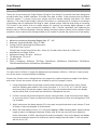
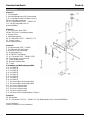
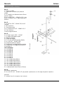
1. Using the diagram within the package contents please build the ceiling to floor mount. Please
leave the following parts aside for use in the next steps: 5, 6, 11, 12 13, 14, 17 and 18. Please
mount and clamp the bracket support clamp (8) in the correct position below where the display
bracket will be fixed, this will stop the bracket from sliding down the pole.
2. Drill the correctly placed mounting holes into the ceiling and floor, fit the mount and screw tightly
to secure the mount. Please see above for fixing hole dimensions of floor and ceiling plates. (Drill
not included).
3. Attach and secure the display bracket (11) to the pole using both brackets to pole clamps (7) and
all fixings. Please see diagram for further detail.
4. Attach the fixed display mounts (17 + 18) to your display’s VESA mounting holes. Use the correct
length screws to not damage the display (Please refer to the user manual of your display for
further information on VESA mounting points and screw depths). Hook on the display and display
mounts to the display bracket (11) and secure with the display bracket holder. Fix this into place
with the R-Pin (12).

User Manual English
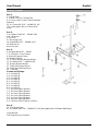
Package Contents
Box 1:
1. Ceiling Plate
2. Plastic Cover for Ceiling Plate
6. 4 x Inner: 8mm* Outer: 18mm Diameter
Washers
20. 4 x Screw BH 5/16” – 18UNC*L2 1/2 “
(For ceiling plate) with 4 x Plastic Wall
Plugs
Box 2:
3. 4 x Screw Top 5/16” – 18UNC*L3/4
with 2 Washers
4.Top Pole
9.Connecting Pole
10.2 x bolt BH 5/16” – 18UNC*L2 ¼”
15.Bottom Pole
6mm Hex Key
Box 3:
5.4 x Nylon Nut 5/16” – 18UNC
7. 2 x Bracket – Pole Clamps
8. Bracket Support Clamp
11.Display Bracket
12. R Pin for Display Bracket Holder
13. 4 x Screw 5/16” – 18UNC*L5/8”
14. Display Bracket Holder
17. Fixed Left Display Mount
18. Fixed Right Display Mount
19. T-Handle
Screws and Fixings:
A-1. 4 x M4*L35
A-2. 4 x M5*L35
A-3. 4 x M6*L35
A-4. 4 x M8*L35
B-1. 4 x M4*L12
B-2. 4 x M5*L15
B-3. 4 x M6*L15
B-4. 4 x M8*L15
C-1. 4 x 6mm*18mm Washer
C-2. 8 x 8mm*18mm Washer
D-1. 4 x 4mm Spring Washer
D-2. 4 x 5mm Spring Washer
D-3. 4 x 6mm Spring Washer
D-4. 4 x 8mm Spring Washer
E. 4 x 8.5mm*15mm Spacer (L20mm)
Box 4:
16. Floor Base Plate
21. 6 x Screw CSK 1/4” – 20UNC*L2” (For floor plate) with 6 x Plastic Wall Plugs
Lindy Manual
Drill Required (not included)

Benutzerhandbuch Deutsch
Einführung
Wir freuen uns, dass Ihre Wahl auf ein LINDY-Produkt gefallen ist und danken Ihnen für Ihr Vertrauen.
Sie können sich jederzeit auf unsere Produkte und einen guten Service verlassen. Diese Boden-Decken-
Halterung für einen Monitor unterliegt einer 2-Jahres LINDY Herstellergarantie und lebenslangem
kostenlosen, technischen Support. Bitte lesen Sie diese Anleitung sorgfältig und bewahren Sie sie auf.
Die Lindy Boden-Decken-Halterung für einen Monitor ist eine professionelle AV-Lösung zur Montage eines
Displays, das keine Wandbefestigung benötigt. Diese Boden-Decken-Halterung ist eine perfekte und
stabile Lösung für ein auffallendes Digital-Signage-System in Schaufenstern oder Galerien für Werbung
und Präsentationen. Durch die schmale, verstellbare Säule zur Befestigung des Displays gibt es keine
Ablenkung vom Bildschirm. Der Betrachter kann Videos in vollem Umfang geniessen. Die flexible Montage
garantiert die optimale Ausrichtung des Displays.
Spezifikationen
▪ Unterstützte Displaygröße: 37” – 60”
▪ Maximal unterstütztes Gewicht: 35kg (77.16lb)
▪ Lochgrößen für Boden- und Deckenmontage:
Bodenplatte: 7mm Ø
Deckenplatte: große Löcher 10mm (W) x 15mm (H), kleine Löcher: 8mm (W) x 13mm (H)
▪ Einstellbare Säulen-/Stangenhöhe: 254.4cm – 306.4cm
▪ Neigungseinstellung: -20° to +5°
▪ Rotation: 360°
▪ VESA-Kompatibilität: 50x50mm, 75x75mm, 100x100mm, 100x200mm, 200x200mm, 300x200mm,
300x300mm, 400x200mm, 400x400mm, 600x400mm
Installation
Diese Säulenhalterung ist 250cm hoch und von 254.4cm bis 306.4cm verstellbar. Beachten Sie dies
bitte vor der Installation.
Stellen Sie auch sicher, dass Boden und Decke das kombinierte, maximale Gewicht von Display und
Halterung unterstützen und dass alle Teile gemäß Lieferumfang enthalten sind.
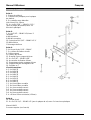
1. Montieren Sie die Boden-Decken-Halterung mithilfe der Abbildung im Handbuch. Legen Sie am
Anfang die folgenden Teile beiseite (diese werden erst später benötigt): 5, 6, 11, 12, 13, 14, 17
und 18. Montieren Sie die Klemme für die Halterung (8) in der korrekten Position unterhalb der
Stelle, an der die Displayhalterung festgemacht wird. Dadurch kann die Halterung nicht nach
unten rutschen.
2. Bohren Sie Löcher in Decke und Boden und schrauben Sie die Halterung fest. Die Abmessungen
für Boden- und Deckenplatte finden Sie oben. (Bohrer nicht enthalten).
3. Befestigen Sie die Displayhalterung (11) an der Stange. Verwenden Sie dazu beide Klammern
für die Stange (7) und das Befestigungsmaterial (siehe Abbildung oben).
4. Befestigen Sie die Displayhalter (17 + 18) an den VESA-Bohrlöchern Ihres Displays. Achten Sie
darauf, dass Sie Schrauben mit korrekter Länge verwenden, so dass das Display nicht
beschädigt wird (sehen Sie nach Details im Handbuch Ihres Displays nach). Hängen Sie das
Display mit den Displayhaltern an die Displayhalterung (11) und sichern Sie diese mit der
Fixierstange für die Halterung. Befestigen Sie diese mit dem R-Stift (12).

Benutzerhandbuch Deutsch
Lieferumfang
Karton 1:
1. Deckenplatte
2. Kunststoffabdeckung für Deckenplatte
6. 4 x Unterlegscheiben mit 8mm* Innen-/
18mm Außendurchmesser
20. 4 x Schraube BH 5/16” – 18UNC*L2
1/2 “ (für Deckenplatte) mit 4 x
Kunststoffdübel
Karton 2:
3. 4 x Schraube, oben 5/16” –
18UNC*L3/4 mit 2 Unterlegscheiben
4. Stange, oben
9. Verbindungsstück
10. 2 x Bolzen BH 5/16” – 18UNC*L2 ¼”
15. Stange, unten
6mm Inbusschlüssel
Karton 3:
5.4 x Nylonmutter 5/16” – 18UNC
7. 2 x Klammer für die Stange
8. Klemme für die Halterung
11. Displayhalterung
12. R-Stift für Fixierstange
13. 4 x Schraube 5/16” – 18UNC*L5/8”
14. Fixierstange zur Sicherung
17. Linker Displayhalter
18. Rechter Displayhalter
19. T-Griff
Schrauben und Befestigungsmittel:
A-1. 4 x M4*L35
A-2. 4 x M5*L35
A-3. 4 x M6*L35
A-4. 4 x M8*L35
B-1. 4 x M4*L12
B-2. 4 x M5*L15
B-3. 4 x M6*L15
B-4. 4 x M8*L15
C-1. 4 x 6mm*18mm Unterlegscheibe
C-2. 8 x 8mm*18mm Unterlegscheibe
D-1. 4 x 4mm Federscheibe
D-2. 4 x 5mm Federscheibe
D-3. 4 x 6mm Federscheibe
D-4. 4 x 8mm Federscheibe
E. 4 x 8.5mm*15mm Abstandhalter (L20mm)
Karton 4:
16. Basisplatte
21. 6 x Schraube CSK 1/4” – 20UNC*L2” (für Bodenplatte) mit 6 x Kunststoffdübeln
Lindy Handbuch
Bohrer erforderlich (nicht enthalten)

Manuel Utilisateur Français
Introduction
Nous sommes heureux que votre choix se soit porté sur un produit LINDY et vous remercions de votre
confiance. Vous pouvez compter à tout moment sur la qualité de nos produits et de notre service. Ce
Support Colonne Sol-Plafond pour Ecran est soumis à une durée de garantie LINDY de 2 ans et d’une
assistance technique gratuite à vie. Merci de lire attentivement ces instructions et de les conserver pour
future référence. Le Support Colonne Sol-Plafond pour Ecran est une solution professionnelle pour le
montage d'un écran sans besoin d'utiliser un mur pour la fixation, mais en utilisant sol et plafond pour le
montage. Ce support est la solution tout-en-un parfaite pour créer un affichage numérique accrocheur
dans les vitrines ou les espaces de vente au détail. Avec un poteau ajustable supportant l'écran, vous
assurez un impact maximum et une expérience visuelle optimale tout en offrant une flexibilité de
montage à l'installateur.
Spécifications
▪ Taille d’écran minimum et maximum pris en charge: 37” – 60”
▪ Poids maximum supporté: 35kg (77.16lb)
▪ Dimensions des trous de fixation:
Plaque de base: 7mm Ø
Plaque plafond: perçage large 10mm (W) x 15mm (H), perçage étroits: 8mm (W) x 13mm (H)
▪ Mât ajustable: 250cm
▪ Plage de réglage: 254.4cm – 306.4cm
▪ Réglage du pivot: -20° to +5°
▪ Rotation: 360°
▪ Conformité VESA: 50x50mm, 75x75mm, 100x100mm, 100x200mm, 200x200mm, 300x200mm,
300x300mm400x200mm, 400x400mm, 600x400mm
Installation
Ce mât a une hauteur de 250cm avec un ajustement de 254.4cm – 306.4cm. Veuillez-vous assurer que
l’espace nécessaire est disponible avant d’effectuer l’installation.
Remarque : Veuillez-vous assurer que le plafond et le plancher peuvent supporter le poids maximum
combiné de l'écran et du support. Veuillez également vous assurer que toutes les pièces sont incluses
conformément au contenu de l'emballage.
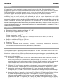
1. En utilisant le schéma inclus, veuillez assembler le mât support. Merci de réserver les pièces
suivantes pour les étapes suivantes: 5, 6, 11, 12 13, 14, 17 et 18. Merci de monter la pince
support (8) à la bonne position en-dessous du support écran, cela évitera au support de glisser le
log du poteau.
2. Percez les trous de montage correctement placés dans le plafond et le sol, ajustez le support et
vissez fermement pour fixer le support. Voir ci-dessus pour les dimensions des trous de fixation
des plaques de plancher et de plafond. (Perceuse et nécessaire de fixation ne sont pas fournis).
3. Fixez le support d'affichage (11) au poteau à l'aide des deux supports (7) et à toutes les fixations.
Veuillez consulter le schéma pour plus de détails.
4. Fixez les supports d'écran fixes (17 + 18) aux trous de fixation VESA de votre écran. Utilisez les
vis de longueur correcte pour ne pas endommager l'écran (pour plus d'informations sur les points
de montage VESA et les profondeurs de vis, reportez-vous au manuel de l'utilisateur de votre
écran). Accrochez l'écran sur le support d'écran (11) et fixez-le le système de blocage (14).
Sécurisez le tout à l'aide de l'axe R (12).

Manuel Utilisateur Français
Contenu de l’emballage
Boite 1:
1. Plaque de plafond
2. Couvercle en plastique pour la plaque
de plafond
6. 4 x rondelles avec diamètre
Intér.:8mm* Ext.: 18mm
20. 4 x vis BH 5/16” – 18UNC*L2 1/2 “
(pour la plaque de plafond) avec 4 x
bouchons plastique
Boite 2:
3. 4 x vis 5/16” – 18UNC*L3/4 avec 2
rondelles
4.Mât supérieur
9.Mât de connexion
10.2 x boulons BH 5/16” – 18UNC*L2 ¼”
15.Mât inférieur
Clé hexagonale 6mm
Boite 3:
5.4 x écrous Nylon 5/16” – 18UNC
7. 2 x colliers de fixation du mât
8. Collier support
11.Fixation de l'écran
12. Goupille R pour support d'écran
13. 4 x vis 5/16” – 18UNC*L5/8”
14. Accessoire de fixation d'écran
17. Support gauche de montage d'écran
18. Support droit de montage d'écran
19. Poignée en T
Vis et accessoires:
A-1. 4 x M4*L35
A-2. 4 x M5*L35
A-3. 4 x M6*L35
A-4. 4 x M8*L35
B-1. 4 x M4*L12
B-2. 4 x M5*L15
B-3. 4 x M6*L15
B-4. 4 x M8*L15
C-1. 4 x 6mm*18mm rondelle
C-2. 8 x 8mm*18mm rondelle
D-1. 4 x 4mm rondelle ressort
D-2. 4 x 5mm rondelle ressort
D-3. 4 x 6mm rondelle ressort
D-4. 4 x 8mm rondelle ressort
E. 4 x 8.5mm*15mm entretoise (L20mm)
Boite 4:
16. Plaque de sol
21. 6 x vis CSK 1/4” – 20UNC*L2” (pour la plaque de sol) avec 6 x bouchons plastique
Manuel LINDY
Perceuse requise (non fournie)

Manuale Italiano
Introduzione
Vi ringraziamo per aver acquistato il supporto per schermi su palo Lindy. Questo prodotto è stato
progettato per garantirvi la massima affidabilità e semplicità di utilizzo ed è coperto da 2 anni di garanzia
LINDY oltre che da un servizio di supporto tecnico a vita. Per assicurarvi di farne un uso corretto vi
invitiamo a leggere attentamente questo manuale e a conservarlo per future consultazioni.
Il supporto per schermi singoli su palo Lindy è un sistema di installazione AV professionale per posizionare
un display dove non sono presenti pareti utilizzando un palo da fissare al pavimento e al soffitto
consentendo di sfruttare in modo ottimale gli spazi. Questo sistema fornisce una grande stabilità e
permette di realizzare soluzioni accattivanti posizionando gli schermi all’altezza desiderata in vetrine o altri
contesti commerciali. Grazie al palo regolabile su cui viene ancorato lo schermo sarà libero da altri
elementi che distraggano l’utente dalla visione dei contenuti assicurando il massimo impatto e un punto di
visione ottimale garantendo nel contempo all’installatore la massima flessibilità e semplicità in fase di
installazione e posizionamento.
Caratteristiche
▪ Dimensioni minima e massima del Display: 37” – 60”
▪ Massimo peso supportato: 35kg (77.16lb)
▪ Diametro dei fori per il montaggio a soffitto e pavimento:
Piastra a pavimento: 7mm Ø
Piastra a soffitto: Fori più ampi 10mm (L) x 15mm (A), Fori più piccoli: 8mm (L) x 13mm (A)
▪ Lunghezza del palo regolabile: 250cm
▪ Raggio di regolazione: 254.4cm – 306.4cm
▪ Regolazione inclinazione: -20° a +5°
▪ Rotazione: 360°
▪ Conformità standard VESA: 50x50mm, 75x75mm, 100x100mm, 100x200mm, 200x200mm,
300x200mm, 300x300mm400x200mm, 400x400mm, 600x400mm
Installazione
Questo palo da 250cm è regolabile in altezza fra 254.4cm e 306.4cm. Assicuratevi di rilevare con cura la
misura richiesta dalla vostra installazione prima di iniziare.
Nota bene: Assicuratevi che soffitto e pavimento possano ampiamente reggere il peso del display e del
supporto combinati. Prima di iniziare controllate anche che tutte le parti elencate in questo manuale
siano presenti nella confezione.
1. Assemblate il supporto come indicate nello schema del contenuto della confezione. Separate e
tenete a disposizione per i passi successivi le seguenti parti: 5, 6, 11, 12 13, 14, 17 e 18. Vi
preghiamo di montare e agganciare la staffa di supporto (8) nella posizione corretta appena sotto
a dove le staffe dello schermo saranno fissate. Questa operazione impedirà alla staffa di
scivolare in basso.
2. Effettuate i fori con il trapano nel soffitto e nel pavimento in corrispondenza dei fori nelle piastre a
soffitto e pavimento. Vedete sopra per conoscere la dimensione dei fori (trapano non incluso).
3. Aggangiate e assicurate le staffe per display (11) al palo utilizzando entrambe le staffe di
fissaggio al palo (7) e tutta la relativa viteria. Fate riferimento al diagramma per ulteriori dettagli.
4. Agganciate e fissate i supporti per lo schermo (17 + 18) ai fori VESA del vostro Display. Utilizzate
le viti della lumghezza giusta per evitare di danneggiare lo schermo (Vi preghiamo di far
riferimento al manuale del vostro Display per avere maggiori dettagli sulle dimensioni VESA e
sulla lunghezza delle viti). Agganciate lo schermo e le staffe di montaggio alla staffa per display
(11) e assicurateli con il supporto staffa display (14). Fissatelo in posizione con l’R-Pin (12).

Manuale Italiano
Contenuto della confezione
Box 1:
1. Piastra a soffitto
2. Copuertura in plastica per piastra a
soffitto
6. 4 x rondelle con diametro interno: 8mm*
esterno: 18mm
20. 4 x viti BH 5/16” – 18UNC*L2 1/2 “ (per
piastra a soffitto) con 4 x tappi da parete in
plastica
Box 2:
3. 4 x viti Top 5/16” – 18UNC*L3/4 con 2
rondelle
4. Palo superiore
9. Connessioni palo
10. 2 x bullone BH 5/16” – 18UNC*L2 ¼”
15. Palo inferiore
Chiave esagonale 6mm
Box 3:
5. 4 x dadi in Nylon 5/16” – 18UNC
7. 2 x staffe di fissaggio al palo
8. Staffa di supporto
11. Staffa per display
12. Pin R per staffa di supporto display
13. 4 x viti 5/16” – 18UNC*L5/8”
14. Supporto staffa per display
17. Supporto di montaggio display sinistro
18. Supporto di montaggio display destro
19. Manigli a T
Viti e minuteria:
A-1. 4 x M4*L35
A-2. 4 x M5*L35
A-3. 4 x M6*L35
A-4. 4 x M8*L35
B-1. 4 x M4*L12
B-2. 4 x M5*L15
B-3. 4 x M6*L15
B-4. 4 x M8*L15
C-1. 4 x rondella 6mm*18mm
C-2. 8 x rondella 8mm*18mm
D-1. 4 x rondella elastica 4mm
D-2. 4 x rondella elastica 5mm
D-3. 4 x rondella elastica 6mm
D-4. 4 x rondella elastica 8mm
E. 4 x distanziale 8.5mm*15mm (L20mm)
Box 4:
16. Piastra a pavimento
21. 6 x viti CSK 1/4” – 20UNC*L2” (per piastra a pavimento) con 6 x tappi da parete in plastica
Manuale
E' richiesto l'uso di un trapano (non incluso)

LINDY Herstellergarantie – Hinweis für Kunden in Deutschland
LINDY gewährt für dieses Produkt über die gesetzliche Regelung in Deutschland hinaus eine zweijährige Hersteller-
garantie ab Kaufdatum. Die detaillierten Bedingungen dieser Garantie finden Sie auf der LINDY Website aufgelistet
bei den AGBs.
Hersteller / Manufacturer (EU):.
LINDY-Elektronik GmbH LINDY Electronics Ltd
Markircher Str. 20 Sadler Forster Way
68229 Mannheim Stockton-on-Tees, TS17 9JY
Germany England
Email: info@lindy.com , T: +49 (0)621 470050 postmaster@lindy.co.uk , T: +44 (0)1642 754000
No. 40968
2
nd
Edition, September 2019
lindy.com
-
 1
1
-
 2
2
-
 3
3
-
 4
4
-
 5
5
-
 6
6
-
 7
7
-
 8
8
-
 9
9
-
 10
10
-
 11
11


Lindy Single Display Ceiling to Floor Mount Manuel utilisateur
- Catégorie
- Supports de bureau à panneau plat
- Taper
- Manuel utilisateur
dans d''autres langues
Documents connexes
Autres documents
-
Samsung OM55N-D Guide d'installation
-
Kimex 032-3014 Guide d'installation
-
LG PL-S860 Le manuel du propriétaire
-
-
 HoistFitness H-4400 Le manuel du propriétaire
-
Kicker 47KMFC CIC Le manuel du propriétaire
-
Ergotron Neo-Flex Mobile MediaCenter LD Mode d'emploi
-
Chief ICLPFA1T02 Guide d'installation
-
-
OmniMount OE120IW Manuel utilisateur
