Dacor Distinctive DTO130 Guide d'installation
- Taper
- Guide d'installation

Installation Instructions
Distinctive
®
Wall Oven
Models: DTO127, DTO130, DTO227, DTOV230,
DTOV227, DTOV130, DTOV227, DTOV230
Français - Voir page 15

All specifications are subject to change without notice. Dacor
®
assumes no liability for changes to specifications.
© 2014 Dacor, all rights reserved.

1
Installation Specifications ................................................ 6
Installation Planning ......................................................... 6
Installation Instructions .................................................... 8
Verify the Package Contents ............................................ 8
Remove the oven door(s) ................................................ 8
Electrical Connection ....................................................... 9
Installing the Oven in the Cabinet .................................. 12
Reinstalling the Oven Door ............................................ 13
Verifying Proper Operation ............................................. 13
Installation Checklist ...................................................... 14
Notes................................................................................. 15
Table of Contents
Important Information About
Safety Instructions
• The Important Safety Instructions and warnings in
these instructions are not meant to cover all possible
problems and conditions that can occur. Use common
sense and caution when installing, maintaining or oper-
ating this or any other appliance.
• Always contact the Dacor Customer Service Team
about problems and conditions that you don’t under-
stand. See Customer Service Information.
Safety Symbols and Labels
DANGER
Immediate hazards that WILL result in severe personal
injury or death.
WARNING
Hazards or unsafe practices that COULD result in severe
personal injury or death.
CAUTION
Hazards or unsafe practices that COULD result in minor
personal injury or property damage.
READ AND SAVE
THESE INSTRUCTIONS
Before You Begin...
Before You Begin... ........................................................... 1
Important Safety Instructions .......................................... 1
Important Information About Safety Instructions .............. 1
Safety Symbols and Labels ............................................. 1
General Safety Precautions ............................................. 2
Customer Service Information ......................................... 3
If You Need Help... ........................................................... 3
Appliance Data Plate ....................................................... 3
Model Identification .......................................................... 3
Product Specifications ..................................................... 4
Electrical Specifications ................................................... 4
Product Dimensions ......................................................... 4
Important Safety Instructions
Important:
• Installer: In the interest of safety and to minimize problems, read these installation instructions completely and care-
fully before you begin the installation process. Leave these installation instructions with the customer.
• Customer: Keep these installation instructions for future reference and the local electrical inspector’s use.
DANGER
IMPORTANT: Do not store or use combustible, flam-
mable, or explosive vapors and liquids (such as gasoline)
inside or in the vicinity of this or any other appliance. Also
keep items that could explode, such as aerosol cans,
away from the oven. Do not store flammable or explosive
materials in adjacent cabinets or areas.
WARNING
WARNING – NEVER use this appliance as a space
heater to heat or warm the room. Doing so may result in
overheating of the appliance.
WARNING
WARNING – NEVER cover any slots, holes or passages
in the oven bottom or cover an entire rack with materials
such as aluminum foil. Doing so blocks air flow through
the oven and may cause a fire hazard.
WARNING
Do not install this appliance outdoors and/or near water,
for example, near a pool.
WARNING
When using the BROIL and CONVECTION BROIL set-
tings, the oven door must be completely shut.

2
Important Safety Instructions
• Read the accompanying use and care manual com-
pletely before operating this appliance.
• Keep packaging materials away from children.
Plastic sheets and bags can cause suffocation.
• If you receive a damaged product, immediately con-
tact your dealer or builder. Do not install or use a
damaged appliance. Do not install or use the appli-
ance if the conduit is damaged.
• This oven must be properly installed and grounded
by a qualified installer according to these instal-
lation instructions prior to use. The installer must
show the customer the location of the circuit
breaker panel or fuse box so that they know where
and how to turn off power to the oven. Dacor is not
responsible for service required to correct a faulty
installation. The owner is responsible to make sure
this appliance is properly installed.
• Do not use the door handle(s) to lift or move the
oven.
• A minimum of two people are required to safely
install this appliance.
• To avoid an electric shock hazard, do not install this
appliance outside or near water. Do not install or
use this appliance if it has been exposed to water.
• Do not install, repair or replace any part of the oven
unless specifically recommended in the literature
accompanying it. A qualified service technician
must perform all other service.
• Before performing any type of service or installa-
tion, make sure that power to the oven is turned off
at the circuit breaker or fuse box.
• Only use the oven for cooking tasks expected of a
home appliance as outlined in the literature accom-
panying it. This oven is not intended for commercial
use.
• Do not climb on any part of the appliance.
• Do not leave children alone or unattended in the
area around the oven. Do not allow children to play
with the controls, pull on the handle or touch other
parts of the oven.
• Do not store items of interest to children above the
oven. Children could be burned or injured while
climbing on the appliance.
• Do not tamper with the controls. Do not adjust
or alter any part of the oven unless specifically
instructed to do so in this manual.
WARNING
General Safety Precautions
To reduce the risk of fire, electric shock, serious injury or death when using your appliance, follow basic safety precau-
tions, including the following:
• To prevent injury due to the unit tipping forward,
secure the oven to the cabinet using the supplied
mounting screws.
• Keep flammable items, such as paper, cardboard,
plastic and cloth away from hot surfaces. Do not put
such items in the oven. Do not allow pot holders to
touch hot surfaces.
• Do not wear loose or hanging apparel while using
the oven. Do not allow clothing to come into contact
with the interior of the oven and the surrounding
areas during and immediately after use.
• Do not use the oven for storage.
• Do not touch the interior surfaces of the oven during
use. After use, make sure these surfaces have had
sufficient time to cool before touching them.
• Do not touch the outside surfaces of the oven dur-
ing the self-clean cycle. They will be hot. Venting
from the oven may cause the trim to become hot.
• For your safety, do not use the oven to cook without
the convection filter installed. When the filter is not
installed, the spinning fan blades at the back of the
oven are exposed.
• Non-stick coatings, when heated, can be harmful to
birds. Remove birds to a separate, well-ventilated
room during cooking.
• To prevent damage, remove the meat probe from
the oven when it is not being used.
• Do not line the oven with aluminum foil or other
materials. These items can melt or burn up during
self-cleaning and cause permanent damage to the
oven.
• Do not leave objects, such as aluminum foil, the
meat probe, cookie sheets, etc. on the bottom of
the oven. Objects left on the bottom of the oven
could damage the oven. In addition, the objects
themselves could be damaged.
• Do not allow heating elements in the top of the oven
chamber to become covered up by cookie sheets,
aluminum foil, pots, pans, etc. Covering the heating
elements could cause them to over-heat, damaging
the oven.
• Always ensure that the light fixture lens covers are
in place when using the oven. The lens covers pro-
tect the light bulbs from breakage caused by high
oven temperatures or mechanical shock.
WARNING

3
Customer Service Information
Model IdentificationIf You Need Help...
If you have questions or problems with installation, contact
your Dacor dealer or the Dacor Customer Service Team.
For repairs to Dacor appliances under warranty call the
Dacor Distinctive Service line. Whenever you call, have the
model and serial number of the appliance ready. The model
and serial number are printed on the appliance data plate.
Dacor Customer Service
Phone: (800) 793-0093 ex. 2813 (U.S.A. and Canada)
Monday — Friday 6:00 a.m. to 5:00 p.m. Pacific Time
Web site: www.dacor.com
Dacor Distinctive Service (repairs under warranty only)
Phone: (800) 793-0093 ex. 2822 (U.S.A. and Canada)
Monday — Friday 6:00 a.m. to 5:00 p.m. Pacific Time
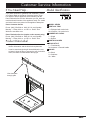
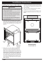
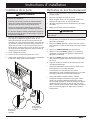
Product Data Label
• The product data label contains the model and serial
number information and the electrical requirements.
• It can be seen through the grill located below the con-
trol panel. Open the door to expose the grill. On double
ovens, the label is located behind the top grill.
View data plate
through grate
DTOV230FS
A MODEL SERIES
B VERTICAL TRIM
V = Equipped with vertical trim
No character = No vertical trim
C NUMBER OF OVENS:
1 = Single
2 = Double
D WIDTH IN INCHES
E DOOR STYLE
F = Flush handle
No character = External handle
F COLOR
B = Black
S = Stainless
W = White
A BC D E F

4
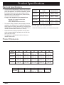
Electrical Specifications
• It is the owner’s responsibility to ensure that a licensed
electrician performs the installation of the electrical sup-
ply for this appliance. The electrical installation, includ-
ing minimum supply wire size, must comply with the
National Electric Code ANSI/NFPA 70 (latest revision)
and local codes and ordinances.
A copy of this standard may be obtained from:
• The correct voltage, frequency and amperage must be
supplied to the appliance from a dedicated, grounded,
single phase circuit that is protected by a properly sized
circuit breaker or time-delay fuse. If a time-delay fuse is
utilized, fuse both sides of the line (L1 and L2).
• Preheat times and cavity temperature recovery times
will be increased slightly if operating the unit with less
than a 240 Vac circuit.
• This appliance is provided with electrical wiring in a
flexible metal conduit.
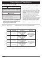
Product Specifications
Model
Number
Total Connected
Load*
Dedicated Circuit
Requirements
DTO(V)127
240 Vac 60 Hz,
23.3 Amp., 5.6 kW
240 Vac 60 Hz,
4 wire**, 30 Amp.
DTO(V)130
240 Vac 60 Hz,
24.9 Amp., 6.0 kW
240 Vac 60 Hz,
4 wire**, 30 Amp.
DTO(V)227
240 Vac 60 Hz,
26.6 Amp., 6.4 kW
240 Vac 60 Hz,
4 wire**, 40 Amp.
DTO(V)230
240 Vac 60 Hz,
26.6 Amp., 6.4 kW
240 Vac 60 Hz,
4 wire**, 40 Amp.
* This specification is for reference only. See the product
data label (page 3) for exact specifications.
** Two 120 Vac hot (L1 and L2), one neutral, one ground.
National Fire Protection Association
1 Batterymarch Park
Quincy, Massachusetts 02269-9101
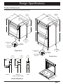
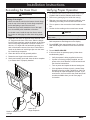
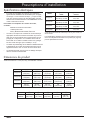
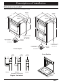
Product Dimensions
All tolerances: ±1/16 (±1.6 mm), unless otherwise stated.
Model (A) (B) (C) (D) (E)
DTO(V)127
26 7/8”
(68.3 cm)
25 3/8”
(64.5 cm)
27 3/4”
(70.5 cm)
26 5/8”
(67.6 cm)
1 1/8”
(2.9 cm)
DTO(V)130
29 7/8”
(75.9 cm)
28 3/8”
(72.1 cm)
27 3/4”
(70.5 cm)
26 5/8”
(67.6 cm)
1 1/8”
(2.9 cm)
DTO(V)227
26 7/8”
(68.3 cm)
25 3/8”
(64.5 cm)
50 1/8”
(127.3 cm)
49”
(124.5 cm)
1 1/8”
(2.9 cm)
DTO(V)230
29 7/8”
(75.9 cm)
28 3/8”
(72.1 cm)
50 1/8”
(127.3 cm)
49”
(124.5 cm)
1 1/8”
(2.9 cm)
(F) (G) (H) (J) (K)
All models
6 1/2”
(16.5 cm)
5”
(12.7 cm)
7 7/8”
(20.0 cm)
1 1/4”
(3.2 cm)
23 1/2”
(59.7 cm)

5
C
J
B
H
G
F
A
Control panel
side view
Control panel
front
Top of
chassis
Top of
chassis
Utility
cutout
Conduit:
60” (152 cm)
long
K
E
D
C
A
Conduit:
60” (152 cm)
long
D
J
B
H
G
F
Top of
chassis
Utility
cutout
K
Control panel
side view
Control panel
front
Top of
chassis
E
Design Specifications
3 1/2”
(8.9 cm)
3 3/16”
(8.1 cm)
1 1/8”
(2.9 cm)
1 1/8”
(2.9 cm)
1 1/8”
(2.9 cm)
Product Dimensions
All tolerances: ±1/16 (±1.6 mm), unless otherwise stated.
Handle Dimensions
Epicure
Millennia
(Order kit #AROVH30S)
Flush
Double Oven
Single Oven
21 7/8”
(55.6) cm

6
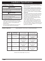
Installation Specifications
Installation Planning
WARNING
Observe all governing codes and ordinances during plan-
ning and installation. Contact your local building depart-
ment for further information.
IMPORTANT
• Locate the junction box so that the oven may be easily
disconnected in the event that it needs to be removed
from the wall completely for service.
• If the oven is not installed level it may deliver poor or
inconsistent baking results.
• Carefully check the location where the oven is to be
installed. The oven should be placed for convenient
access. Make certain that electrical power, meeting the
specifications on page 4, can be provided in the
selected location.
• Dacor recommends installing the junction box in the
one of the locations shown on the facing page.
Minimum interior cabinet depth: 24” (61.0 cm)
• Install the junction box in a location that allows the
oven to be removed from the cutout for service without
being disconnected.
• Plan the installation so that all minimum clearances
are met or exceeded. Dimensions shown provide mini-
mum clearances, unless otherwise noted. Be certain
that proper clearance is provided for the oven door
when it is in the open position according the Product
Dimensions.
• Cabinet cutout dimensions must be used as indicated.
The specified minimum cabinet depth and width must
be provided. The cabinet depth and width must com-
pletely enclose the recessed portion of the oven.
• All contact surfaces between the appliance and the
cabinet must be solid and level.
• Provide a platform within the cabinet to support the
oven. It must be installed level and straight. The top
edge of the platform must be flush with the cutout at
the front of the cabinet. There are no provisions to level
the oven after it has been installed. 3/4” (1.9 cm) thick
plywood is recommended.
Model
Number
(N) Minimum
Cabinet Width
(P) Cutout Width (R) Cutout Height
DTO(V)127 27” (68.6 cm)
25 1/2” (64.8 cm)
minimum (recommended)
26 1/8” (66.4 cm)
maximum
26 3/4” (67.9 cm)
minimum (recommended)
27 1/2” (69.9 cm)
maximum
DTO(V)130 30” (76.2 cm)
28 1/2” (72.4 cm)
minimum (recommended)
29 1/8” (74.0 cm)
maximum
26 3/4” (67.9 cm)
minimum (recommended)
27 1/2” (69.9 cm)
maximum
DTO(V)227 27” (68.6 cm)
25 1/2” (64.8 cm)
minimum (recommended)
26 1/8” (66.4 cm)
maximum
49 1/8” (124.8 cm)
minimum (recommended)
50” (127.0 cm)
maximum
DTO(V)230 30” (76.2 cm)
28 1/2” (72.4 cm)
minimum (recommended)
29 1/8” (74.0 cm)
maximum
49 1/8” (124.8 cm)
minimum (recommended)
50” (127.0 cm)
maximum
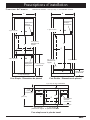
Cabinet Dimensions
Cabinet tolerances: +1/16 (1.6 mm), -0, unless otherwise stated.

7
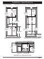
Installation Specifications
4” typical toe kick
Recommended
electrical
location
N
P
R
3/4” (1.9 cm)
support platform
1” (2.5 cm) min.
to bottom of
cabinet door
1” (2.5 cm) min.
to top of
drawer face
9 5/8” (24.4 cm)
recommended
Recommended
electrical
location
Alternate
electrical
location
4” typical toe kick
P
R
3/4” (1.9 cm)
support platform
31 1/4” (79.4 cm)
recommended
1” (2.5 cm) min.
to bottom of
cabinet door
1” (2.5 cm) min.
to top of
cabinet door
N
1 1/2”
(3.8 cm)
typical counter
1“ (2.5 cm) min.
to combustible floor
3/4” (1.9 cm)
support platform
1“ (2.5 cm) min. to combustibles
Recommended
electrical
location
4” typical toe kick
36” typ.
(91.4 cm)
P
R
Cabinet Dimensions
Single Wall Oven - Installed Under Counter
Single Wall Oven - Cutout Dimensions Double Wall Oven - Cutout Dimensions
Cabinet tolerances: +1/16 (1.6 mm), -0, unless otherwise stated.

8
Installation Instructions
Verify the Package Contents
Verify that all the components below have been provided. If any item is missing or damaged, please contact your dealer
immediately. Do not install a damaged or incomplete appliance. Make sure that you have everything necessary to ensure
proper installation before proceeding.
• Dacor Stainless Steel Cleaner
(stainless steel models only)
• Meat probe
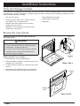
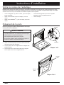
Remove the oven door(s)
• Use and care manual
• Mounting screws, wood, #6 X ¾, Dacor PN 83331,
4 for single ovens, 6 for double ovens
• Standard oven racks (single ovens come with 2,
double ovens come with 4)
• GlideRack™ oven rack (single ovens come with 1,
double ovens come with 2)
Remove the door(s) to reduce weight and make the
oven easier to lift:
WARNING
• Do not attempt to disengage the hinge catches with
the door removed from the oven. The hinge springs
could release, causing personal injury.
• Do not lift or carry the oven door by the door handle.
• On double ovens, remove the bottom door first to
reduce the chance of damage.
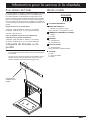
Removing the Oven Door(s)
1. Open the door to its fully opened position.
2. Using a flat blade screwdriver, rotate the catch over the
retaining arm on each hinge.
3. Lift the oven door to about a 15° angle from the vertical
position.
4. Hold the door with both hands just below the handle
and pull it away from the oven while continuing to lift.
Gripping
point
Gripping
point
Steps 3 and 4
Retaining
arm
Catch
Steps 1 and 2

9
Installation Instructions
Electrical Connection
WARNING
• If the electrical service provided does not meet the
Electrical Specifications (see page 4), do not
proceed with the installation. Call a licensed electrician
to correctly install the required wiring.
• Failure to disconnect power prior to installation may
result in an electric shock or fire hazard.
• Do not turn on power to the appliance until the oven is
properly grounded according to these instructions.
• The installer must connect the ground terminal (or
lead) on the appliance to a grounded, metallic, perma-
nent wiring system or grounding conductor. Failure to
do so may result in an electric shock hazard.
• Do not use an extension cord with this appliance. Such
use may result in fire, electric shock or personal injury.
• Do not install a fuse in the neutral or ground circuit. A
fuse in the neutral or ground circuit may result in an
electric shock hazard.
• The appliance must be connected to the power supply
with copper wire only. The use of aluminum wire may
result in unsatisfactory conditions.
IMPORTANT
Provide slack in the conduit to allow the oven to slide for-
ward for servicing.
NOTE
The electrical connection leads from the supplied appli-
ance conduit may be a smaller gage than the standard
household wiring of the dedicated supply circuit. They
are suitable for connection to household wiring under the
jurisdiction of the National Electric Code, and/or the local
inspection authority.
1. Before proceeding, turn off power to the circuit to which
the oven will be connected at the circuit breaker or fuse
box.
2. Position the oven directly in front of the cabinet cutout.
3. Feed the appliance conduit into the junction box and
attach it using a UL approved strain relief.
4. Depending upon local codes, utilize one of three meth-
ods to connect the appliance to power:
◊ Connect to a four wire electrical system
◊ Connect to a three wire electrical system, where
local codes permit
◊ Connect to a three wire electrical system with
external ground, according to local codes.
See pages 9 to 11 for detailed directions.
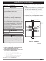
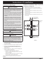
Connecting to a Four Wire Electrical
System
1. Separate the wires coming out of the appliance conduit.
2. Connect the white wire from the appliance conduit to
the white (neutral) supply wire in the junction box.
3. Connect the black wire from the appliance conduit to
the black (L1) supply wire in the junction box.
4. Connect the red wire from the appliance conduit to the
red (L2) supply wire in the junction box.
5. Connect the green wire from the appliance conduit to
the green (ground) wire in the junction box.
continued...
Incoming power
RED
RED
WHITE
WHITE
GREEN
GREEN
BLACK
BLACK
Wire nut,
4 places
Junction box
Conduit to
oven
Four Wire Connection

10
Installation Instructions
Electrical Connection - (continued)
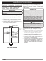
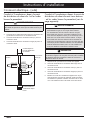
Connecting to a Three Wire Electrical
System - Where Local Codes Permit
WARNING
Do not connect the green appliance conduit wire to the
neutral (white) junction box wire unless local building
codes permit.
1. Separate the wires coming out of the appliance conduit.
2. Connect the green and white wires from the appliance
conduit to the white (neutral) supply wire in the junction
box.
3. Connect the black wire from the appliance conduit to
the black (L1) supply wire in the junction box.
4. Connect the red wire from the appliance conduit to the
red (L2) supply wire in the junction box.
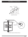
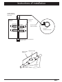
Connecting to a Three Wire Electrical
System with External Ground - Where Local
Codes Permit
WARNING
• Do not ground the appliance to a gas supply pipe or
hot water pipe.
• If connecting the ground wire to a grounded cold water
pipe, connect using a separate copper grounding
wire (No. 10 minimum) and a clamp with an external
grounding screw. The grounded cold water pipe must
have metal continuity to electrical ground and must not
be interrupted by insulating materials. Any insulating
materials must be jumped, with a minimum, 4 AWG
wire to establish continuity to ground. See facing page.
NOTE
If the junction box has been properly grounded by a
licensed electrician, the green (ground) wire from the
appliance conduit may be connected to the junction box
using a loop terminal.
To connect the green appliance conduit wire to a
grounded cold water pipe, see diagrams on facing
page.
1. Separate the wires coming out of the appliance conduit.
2. Connect the white wire from the appliance conduit to
the white (neutral) supply wire in the junction box.
3. Connect the black wire from the appliance conduit to
the black (L1) supply wire in the junction box.
4. Connect the red wire from the appliance conduit to the
red (L2) supply wire in the junction box.
5. Connect the green wire from the appliance conduit to a
grounded cold water pipe as shown. Jumper any insu-
lating materials as shown above with a length of No. 4
copper wire. Securely clamp the wire to bare metal at
both ends.
Incoming power
Wire nut,
3 places
Junction box
Conduit to
oven
Three Wire Connection
RED
RED
WHITE
WHITE
GREEN
BLACK
BLACK

11
Installation Instructions
Three Wire Connection with External Ground
Conduit to
oven
Incoming
power
Wire nut,
4 places
Junction box
Separate 10 AWG
wire minimum
Clamp wire tightly
to pipe
RED
RED
WHITE
WHITE
GREEN
GREEN
BLACK
BLACK
Clamps
Bare metal
Insulating device
4 AWG wire
(minimum)
Insulated Pipe Jumper

12
Installation Instructions
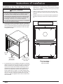
Installing the Oven in the Cabinet
WARNING
• Failure to properly install the mounting screws may
result in movement or tipping of the oven during use,
resulting in personal injury.
• Do not block the oven air exhaust located at the bot-
tom of the oven. Blocking the intake may result in a
fire hazard, cabinet damage or poor performance.
• The wall oven is heavy. Do not attempt to install it in
the cabinet with less than two people.
• Do not use the exhaust grill or the bottom edge of
the oven opening as a gripping point. Damage to the
exhaust grill may result.
1. Lift the wall oven up to the cabinet cutout, using the
upper edge of the cavity opening and the bottom of the
oven case side as gripping points. Be certain to take all
necessary safety precautions due to the weight of the
appliance.
2. Resting the oven on the cabinet-mounting platform,
slide the oven into the recessed area until the rear
edge of the oven frame is flush with the cabinet face
and the oven is centered within the cutout. Ensure that
the electrical conduit slides through the opening in the
cabinet platform or coils above the oven chassis as the
oven is slid into place. The cable must be placed into
the recessed area located along the rear vertical edge
of the oven or coiled above the oven chassis. Do not
trap the appliance cable between the oven case back
and the rear wall.
3. Locate the mounting holes in the trim on both sides
of the oven. There are four (4) holes, two (2) on each
side, for single oven models and six (6) holes for dou-
ble oven models.
4. Use a 1/16” drill bit to drill pilot holes in the cabinet
through all of the trim mounting holes.
5. Install all of the provided #6 screws through the oven
trim into the cabinet to secure the oven. Do not over-
tighten.
Mounting Screws:
Four (4) for single oven
Six (6) for double oven
Gripping
point
Gripping point:
case bottom
both sides
Do not
grip here!

13
Installation Instructions
Reinstalling the Oven Door
WARNING
To avoid personal injury or damage to the door from
it falling off its hinges:
• Make sure that the notch on the bottom of each hinge
rests on top of the lower lip of each hinge receptacle
before attempting to open the oven door.
• Rotate the hinge locks toward the front of the appli-
ance immediately after installation of the door.
• On double ovens, install the top door first to reduce
the chance of damaging the lower door during instal-
lation.
1. Grasp the oven door on opposite sides and hold it at a
15° angle from the front of the oven. Slide the hinges
into the hinge openings, resting the bottom of the hinge
arms on the hinge receptacles. Continue to hold the
door at a 15° angle with one hand while pushing in on
each of the bottom corners of the door. Push until the
notch on the bottom of each hinge slips over the lower
lip of each hinge receptacle.
2. Lower the door to the fully opened position.
3. Rotate the two hinge locks toward the oven.
4. Slowly and carefully open and close the door complete-
ly to ensure that it is properly installed.
Notch on bottom
of hinge
Lower lip of
hinge receptacle
Verifying Proper Operation
1. For stainless steel ovens, peel off the protective layer
of plastic that covers the stainless steel surfaces.
2. Remove any packaging from inside the oven(s).
3. Slide the oven racks onto the supports inside the oven
chamber(s) according to the use and care manual.
4. Turn on power to the oven at the circuit breaker or fuse
box.
5. Set the clock according to the use and care manual.
NOTE
For double ovens, test operation for both the upper and
lower ovens.
6. Press the BAKE key on the control panel. The default
bake temperature should appear on the display.
7. Press START. After approximately three (3) minutes,
heat should begin to radiate from the floor inside the
oven.
8. Press CANCEL/SECURE.
9. If the oven does not operate properly, follow these
troubleshooting steps:
◊ Verify that power is being supplied to the oven.
◊ If power is not being properly supplied, turn off
power at the circuit breaker or fuse box and check
the electrical connections.
◊ Turn on power and repeat the above heating test.
◊ If the appliance still does not work, contact Dacor
Distinctive Service at (800) 793-0093 ex. 2822. Do
not attempt to repair the appliance yourself. If you
need service, be sure to have the model and serial
numbers available when you call. See page 3
for location.

14
Installation Instructions
Installation Checklist
WARNING
To ensure proper installation, the installer must complete
the checklist below to make sure that no part of the in-
stallation has been overlooked.
□ Is the oven mounted on a level platform? See page
6.
□ Is the oven wired and grounded according to these
instructions and in accordance with all applicable elec-
trical codes? See pages 4 and 9.
□ Is the oven secured into the cabinet with all the mount-
ing screws four (4) on single oven models, six (6) on
double ovens? See page 12.
□ Is/are the oven door(s) properly installed according to
these instructions? See page 13.
□ Has proper operation been verified?
□ Has the warranty been activated on-line or the warranty
card been filled out completely and mailed?

Instructions d’installation
Four mural
Modèles : DTO127, DTO130, DTO227, DTOV230,
DTOV227, DTOV130, DTOV227, DTOV230

Les spécifications figurant dans ce manuel sont susceptibles d’être modifiées sans préavis.
Dacor
®
n’assumera aucune responsabilité en cas de modification de ces spécifications.
© 2014 Dacor, tous droits reserves.

17
Table des matières
Ce qui vous devez savoir
instructions de sécurité
• Instructions de sûreté d’avertissement et importantes appa-
raître en ce livre ne sont pas censés couvrir toutes les condi-
tions possibles et situations qui peuvent se produire. Le bon
sens, l’attention et le soin doivent être employés en installant,
en maintenant ou en actionnant un appareil.
• Entrez en contact avec toujours le fabricant au sujet des pro-
blèmes ou des conditions que vous ne comprenez pas. Voir
Information pour le service à la cliente.
Symboles de sûreté, mots et étiquettes
DANGER
Risques immédiats qui RÉSULTERONT en de graves bles-
sures ou même la mort.
ADVERTISSEMENT
Risques ou pratiques non sûres, qui POURRAIENT résulter
en de graves blessures ou même la mort.
MISE EN GARDE
Risques ou pratiques non sûres qui POURRAIENT résulter
en des blessures mineures ou dégâts matériels.
LIRE ET CONSERVER CES
DIRECTIVES
Avant de commencer
Importantes instructions de sécurité
Important :
• Installateur : Dans un souci de sécurité, lire ces instructions d’installation en entier et attentivement avant de commencer le pro-
cessus d’installation. Laisser ces instructions d’installation au propriétaire.
• Propriétaire : Conserver ces instructions d’installation pour vous y reporter en cas de besoin. Conserver ces instructions
d’installation à l’intention du contrôleur d’installations électriques local.
DANGER
IMPORTANT : N’entreposez et n’utilisez pas d’essence ou
autres vapeurs et liquides inflammables a proximite de cet
appareil ou de tout autre appareil electromenager. Garder
les articles qui pourraient exploser, comme les généra-
teurs d’aérosol, éloignés des appareils ménagers. Ne pas
entreposer de produits inflammables ou explosifs dans des
armoires ou zones attenantes (ou au-dessus et au-dessous).
ADVERTISSEMENT
AVERTISSEMENT : NE JAMAIS utiliser cet appareil comme
dispositif de chauffage de la pièce. Le nonrespect de cette
instruction peut entraîner une surchauffe de l’appareil.
ADVERTISSEMENT
AVERTISSEMENT : NE JAMAIS couvrir les fentes, les
trous, les grilles ou les passages sur l’appareil ménager.
Ne
pas revêtir le four de papier d’aluminium ou d’un autre maté-
riel.
Le faire empêche l’air de circuler dans le châssis et peut
causer un incendie.
ADVERTISSEMENT
Ne pas ranger ou utiliser cet appareil à l’extérieur. Ne pas
utiliser ce produit près de l’eau —par exemple, près d’une
piscine.
ADVERTISSEMENT
Lorsqu’on utilise les réglages grillage (BROIL) et grillage par
convection (CONVECTION BROIL), la porte du four doit être
complètement fermée.
Avant de commencer ...................................................... 17
Importantes instructions de sécurité ............................ 17
Ce qui vous devez savoir instructions de sécurité ......... 17
Mesures de sécurité générales ...................................... 18
Information pour le service à la clientele ..................... 19
Pour obtenir de l’aide ..................................................... 19
L’étiquette de données sur le produit ............................. 19
Idendu modèle ............................................................... 19
Prescriptions d’installation ............................................ 20
Spécifications électriques ............................................... 20
Dimensions du produit ................................................... 20
Planification de l’installation ........................................... 22
Instructions d’installation ............................................... 24
Vérifier le contenu de l’emballage .................................. 24
Enlèvement de la porte .................................................. 24
Connexion électrique ..................................................... 25
Installation du four dans l’armoire .................................. 28
Vérification du bon fonctionnement ................................ 29
Liste de vérification de l’installation ............................... 30

18
Importantes instructions de sécurité
• Lire le manuel d’utilisation d’accompagnement en
entier avant d’utiliser l’appareil ménager.
• Garder les emballages éloignés des enfants. Le plas-
tique en feuilles et les sacs peuvent causer la suffoca-
tion.
•
Si le produit reçu est endommagé, contactez immédi-
atement votre revendeur ou votre constructeur. Ne pas
installer ou utiliser un appareil ménager endommagé.
•
Assurez-vous que votre appareil est bien installé et
mis à la terre par un installateur qualifié, conformément
aux les directives d’installation fournies. L’installateur
doit montrer au client l’emplacement du tableau dis-
joncteurs ou du coffret de fusibles afin qu’il sache où
il se trouve et comment couper l’alimentation vers
l’appareil. Dacor n’est pas responsable des répara-
tions nécessaires pour corriger une installation inap-
propriée. L’installation convenable est la responsabilité
du propriétaire.
•
Ne transportez pas le porte par le poignée.
• Au moins deux personnes sont requises pour
l’installation sécuritaire de l’appareil ménager.
• Ne pas installer ni réparer ni remplacer toute pièce du
four si ce n’est pas spécifiquement recommandé dans
les instructions. Toute autre opération d’entretien ou de
réparation doit être confiée à un technicien qualifié.
• Avant de procéder à l’entretien ou à l’installation de cet
appareil ménager, s’assurer que l’électricité est cou
-
pée au niveau du tableau disjoncteurs ou du coffret de
fusibles.
•
N’utilisez cet appareil que pour l’usage auquel il est
destiné, comme expliqué dans le présent manuel. Cet
appareil ménager n’est pas destiné à l’utilisation com-
merciale ou de laboratoire.
•
Ne pas grimper sur aucune partie de l’appareil.
• Ne pas laisser les enfants ou les animaux domestiques
seuls ou sans surveillance dans la zone autour de
l’appareil ménager. Ne pas laisser les enfants jouer
avec les commandes ou toucher d’autres parties de
l’appareil ménager.
• Ne pas entreposer des articles intéressants pour les
enfants sur l’appareil ou au-dessus de ce dernier. Les
enfants pourraient se brûler ou se blesser s’ils grim
-
pent sur l’appareil.
•
Ne pas endommager les commandes. Ne pas rajust-
er ou modifier une partie de la cuisinière à moins
d’indication précise dans les présentes instructions.
•
Afin de prévenir les blessures attribuables au bas-
culement vers l’avant de l’appareil, fixer l’appareil à
l’armoire à l’aide des vis de montage fournies.
ADVERTISSEMENT
Mesures de sécurité générales
Pour réduire le risque d’incendie, de choc électrique, de blessures ou de dommages lors de l’utilisation de cet appareil, il convient
d’observer certaines précautions élémentaires dont les suivantes :
• Garder les articles inflammables, comme le papier, le
carton, le plastique et l’étoffe éloignés des surfaces
chaudes. Ne pas placer produits inflammables à
l’intérieur du four. Ne pas laisser les poignées toucher
les surfaces chaudes.
• Ne pas porter de vêtements amples ou libres pendant
l’utilisation de cet appareil ménager. Ne pas laisser les
vêtements, les poignées, les serviettes ou les chiffons
entrer en contact avec les surfaces chaudes immédi-
atement après l’utilisation.
•
Ne pas utiliser le four pour l’entreposage.
• NE PAS TOUCHER LES SURFACES CHAUDES
DE L’APPAREIL MÉNAGER OU LES ZONES
AVOISINANTES PENDANT OU IMMÉDIATEMENT
APRÈS L’UTILISATION.
• Ne pas toucher les surfaces extérieures de l’appareil
ménager pendant le cycle d’autonettoyage. Elles
seront chaudes. La ventilation du four peut causer le
réchauffement des garnitures.
• Pour des raisons de sécurité et pour un bon rendement
du four, ne pas utiliser le four pour la cuisson sans le
filtre à convection installé. Lorsque le filtre n’est pas
installé, les pales de ventilateur en rotation à l’arrière
du four sont exposées.
• Les revêtements antiadhésifs, lorsqu’ils sont chauffés,
peuvent nuire aux oiseaux. Déplacer les oiseaux à une
salle séparée bien ventilée.
• Afin de prévenir les dommages, retirer la sonde ther
-
mique du four lorsqu’elle n’est pas utilisée.
•
Ne pas revêtir le four de papier d’aluminium ou d’un
autre matériel. Ces articles peuvent fondre ou brûler
pendant l’autonettoyage et endommager le four de
façon permanente.
• Ne pas laisser d’objets, comme du papier d’aluminium,
la sonde thermique ou des plaques à biscuits au bas
du four. Cela pourrait causer la surchauffe du four ou
des articles laissés à l’intérieur, ce qui crée un risque
d’incendie ou cause des dommages.
• Ne pas couvrir les éléments de chauffage au haut de
la chambre de cuisson, avec papier d’aluminium, des
marmites, des poêles, etc. Couvrir les éléments de
chauffage peut causer la surchauffe et endommager le
four.
• Toujours s’assurer que la lentille du dispositif
d’éclairage est en place pendant l’utilisation du four.
La lentille protège l’ampoule du bris causé par les tem
-
pératures élevées du four ou le choc mécanique.
ADVERTISSEMENT
La page est en cours de chargement...
La page est en cours de chargement...
La page est en cours de chargement...
La page est en cours de chargement...
La page est en cours de chargement...
La page est en cours de chargement...
La page est en cours de chargement...
La page est en cours de chargement...
La page est en cours de chargement...
La page est en cours de chargement...
La page est en cours de chargement...
La page est en cours de chargement...
La page est en cours de chargement...
La page est en cours de chargement...
La page est en cours de chargement...
La page est en cours de chargement...
-
 1
1
-
 2
2
-
 3
3
-
 4
4
-
 5
5
-
 6
6
-
 7
7
-
 8
8
-
 9
9
-
 10
10
-
 11
11
-
 12
12
-
 13
13
-
 14
14
-
 15
15
-
 16
16
-
 17
17
-
 18
18
-
 19
19
-
 20
20
-
 21
21
-
 22
22
-
 23
23
-
 24
24
-
 25
25
-
 26
26
-
 27
27
-
 28
28
-
 29
29
-
 30
30
-
 31
31
-
 32
32
-
 33
33
-
 34
34
-
 35
35
-
 36
36


