
BETRIEBSANLEITUNG
MOTORHACKE
441442_c 07 | 2017
DE
GB
NL
FR
IT
Sl
PL
CZ
SK
HU
DK
SE
NO
FI
RU
UA
MH 4005
MH 5007 R

D
2 MH 4005 / MH 5007 R
Inhaltsverzeichnis
D(%etriebsanleitung...................................................................................................
GB Instructions or use....................................................................................................14
NL Gebruikershandleiding............................................................................................20
FR Notice d'utilisation...................................................................................................26
IT Istruzioni per l'uso.................................................................................................. 33
Sl Navodila za uporabo................................................................................................39
PL Instrukcja obsługi....................................................................................................45
CZ Návod k provozu......................................................................................................51
SK Návod na použitie.................................................................................................. 57
HU Üzemeltetési útmutató............................................................................................63
DK Brugsanvisning........................................................................................................69
SE Bruksanvisning........................................................................................................75
NO Bruksanvisning....................................................................................................... 81
FI Käyttöohje...............................................................................................................87
RU Руководство по эксплуатации..............................................................................93
UA Посібник з експлуатації.................................................................................... 100
© 2017
AL-KO KOBER GROUP Kötz, Germany
This documentation or excerpts therefrom may not be reproduced or disclosed to third parties without
the express permission of the AL-KO KOBER GROUP.

441442_c 3

D
4 MH 4005 / MH 5007 R

441442_c 5

D
6 MH 4005 / MH 5007 R

441442_c 7
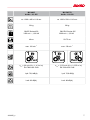
MH 4005
Art.Nr.: 113 255
MH 5007 R
Art.Nr.: 113 620
ca. 1300 x 400 x 1110 mm ca. 1300 x 500 x 1110 mm
29 kg 39 kg
B&S E-Series 450
3100 min
-1
; 1,66 kW
B&S EXi-Series 625
2900 min
-1
; 2,3 kW
40 cm 50-75 cm
max. 120 min
-1
max. 130 min
-1
1
Fwd
1
Fwd
1
Rwd
a
vhw
= 8,6 m/s
2
(K= +/- 4,3 m/ s
2
)
EN 709e ISO 5349
a
vhw
= 13,76 m/s
2
(K= +/- 0,55 m/ s
2
)
EN 709e ISO 5349
LpA: 78,9 dB(A) LpA: 76,9 dB(A)
LwA: 93 dB(A) LwA: 89 dB(A)

D
Original-Betriebsanleitung
8 MH 4005 / MH 5007 R
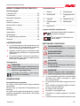
ORIGINAL-BETRIEBSANLEITUNG
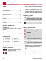
Inhaltsverzeichnis
Zu diesem Handbuch.........................................8
Produktbeschreibung..........................................8
Sicherheitshinweise............................................8
Montage..............................................................9
Inbetriebnahme.................................................10
Wartung und Pflege......................................... 11
Lagerung.......................................................... 11
Zubehörteile......................................................12
Entsorgung....................................................... 12
Hilfe bei Störungen.......................................... 12
EG-Konformitätserklärung................................13
Garantie............................................................13
ZU DIESEM HANDBUCH
Lesen Sie diese Dokumentation vor der Inbe-
triebnahme durch. Dies ist Voraussetzung für
sicheres Arbeiten und störungsfreie Handha-
bung.
Beachten Sie die Sicherheits- und Warnhin-
weise in dieser Dokumentation und auf dem
Produkt.
Diese Dokumentation ist permanenter Be-
standteil des beschriebenen Produkts und
soll bei Veräußerung dem Käufer mit überge-
ben werden.
Zeichenerklärung
ACHTUNG!
Genaues Befolgen dieser Warnhinweise
kann Personen- und / oder Sachschäden
vermeiden.
HINWEIS
Spezielle Hinweise zur besseren Ver-
ständlichkeit und Handhabung.
PRODUKTBESCHREIBUNG
Bestimmungsgemäße Verwendung
Dieses Gerät ist nur zur Bearbeitung eines vorge-
lockerten Bodens bestimmt.
Zur Umarbeitung von festen Böden, z.B. festge-
tretener Rasen, ist dieses Gerät nicht geeignet.
Die weitere Verwendung dieses Gerätes mit Ori-
ginal-Zusatzteilen ist nur entsprechend deren Be-
stimmung erlaubt. Anderweitige Anwendung ist
nicht gestattet.
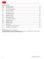
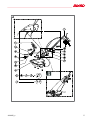
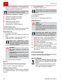
Produktübersicht
1 Gashebel 6 Bremssporn
2 Transportrad 7 Kupplungshebel
3 Hackmesser 8 Hebel für Rück-
wärtsgang
4 Schutzblechver-
breiterung
9 Schutzscheiben
5 Starterseil
Symbole am Gerät
Vor Inbetriebnahme Gebrauchsan-
leitung lesen!
Rotierendes Werkzeug! Hände
und Füße fernhalten!
SICHERHEITSHINWEISE
WARNUNG!
Brandgefahr! Benzin ist hochgradig
entflammbar!
WARNUNG!
Vergiftungsgefahr!
Motor nie in geschlossenen Räumen lau-
fen lassen.
ACHTUNG!
Verbrennungsgefahr!
Der Auspuff, sowie die Bereiche um den
Auspuff können bis zu 80° heiß werden.
ACHTUNG!
Vor Inbetriebnahme immer eine Sicht-
kontrolle durchführen.
Jugendliche unter 16 Jahren oder Personen,
welche die Bedienungsanleitung nicht ken-
nen, dürfen das Gerät nicht benützen.

Sicherheitshinweise
441442_c 9
Das Gerät nicht auf grobsteinigem Gelände
einsetzen.
Örtliche Bestimmungen zum Mindestalter der
Bedienperson beachten.
Keine lose sitzende Kleidung tragen
Festes, rutschsicheres Schuhwerk tragen
Fremdkörper im Arbeitsbereich entfernen.
Das Gerät darf nicht im gewerblichen Einsatz
betrieben werden
Gerät nicht unter Einfluss von Alkohol, Dro-
gen oder Medikamenten bedienen.
Landesspezifische Bestimmungen für die Be-
triebszeiten beachten.
Nur bei ausreichendem Tageslicht oder
künstlicher Beleuchtung arbeiten.
ACHTUNG!
Vor Inbetriebnahme immer eine Sicht-
kontrolle durchführen.
Gerät nur in technisch einwandfreiem Zu-
stand benutzen.
Beachten Sie, dass der Benutzer für Unfälle
und Schäden verantwortlich ist, die anderen
Personen oder deren Eigentum widerfahren
können
Sicherheits- und Schutzeinrichtungen nicht
außer Kraft setzen.
Hände und Füße nicht in die Nähe rotierender
Teile bringen.
Gerät nie mit laufendem Motor heben oder
tragen.
Beim Arbeiten auf sicheren Stand achten
Der Benutzer ist für Unfälle mit anderen Per-
sonen und deren Eigentum verantwortlich.
Gerät nicht unbeaufsichtigt lassen.
Auspuff und Motor sauber halten
Benzin nur in dafür vorgesehenen Behältern
aufbewahren
Nur im Freien tanken
Beschädigten Tank oder Tankverschluss
austauschen
Beschädigte oder verschlissene Teile durch
Original-Ersatzteile ersetzen.
Konstruktions- und Ausführungsänderungen
vorbehalten.
Beim Anlassen (Starten) des Motors darf nie-
mand vor dem Gerät bzw. den Arbeitswerk-
zeugen (Hackmesser) stehen - der Antrieb
der Hackmesser muss ausgeschaltet sein.
Den An- und Abbau des Transportrades,
bzw. das Verstellen des Bremsspornes nur
bei abgeschaltetem Motor und stehenden
Hackmessern vornehmen.
Beim Fahren mit angebautem Transportrad
den Motor abstellen und Stillstand der Hack-
messer abwarten.
Das Benutzen des Gerätes ist nur bei Einhal-
tung des durch den Führungsholm gegebe-
nen Sicherheitsabstandes erlaubt.
Stets quer zum Hang arbeiten.
Nicht hangauf- und hangabwärts, sowie an
Hängen mit mehr als 10° Neigung arbeiten.
Während der Motor läuft oder bei heißer Ma-
schine darf der Tankverschluss nicht geöffnet
oder Benzin nachgefüllt werden.
Zum Auftanken einen Trichter oder ein Ein-
füllrohr verwenden, damit kein Kraftstoff auf
den Motor, das Gehäuse oder die Erde ver-
schüttet werden kann.
Falls Benzin übergelaufen ist, darf der Motor
nicht gestartet werden. Das Gerät ist zu rei-
nigen und jeglicher Zündversuch zu vermei-
den, bis die Benzindämpfe sich verflüchtigt
haben.
Aus Sicherheitsgründen, nie den Motor mit
abgenutzten oder beschädigten Teilen ver-
wenden. Die Teile müssen ersetzt und dür-
fen niemals repariert werden. Originalersatz-
teile verwenden. Nicht gleichwertige Ersatz-
teile können den Motor beschädigen und Ihre
Sicherheit gefährden
Beschädigte Auspufftöpfe austauschen.
Die Reglereinstellungen des Motors nicht
verändern.
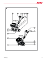
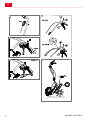
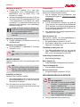
MONTAGE
Montage Bremssporn (2)
Die lange Seite des Bremssporns (2-1) in das
Endstück des Rahmenarms einführen und
blockieren indem man den Griff (2-2) dreht.
Montage Transportrad (3)
Das Transportrad (3-1) dient nur zur Beförderung
der Motorhacke.
Transportrad (3-1) auf Bremssporn aufschie-
ben und mittels der Sternschraube (3-2) be-
festigen.

D
Montage
10 MH 4005 / MH 5007 R
Während der Arbeit ist das Transportrad zu ent-
fernen:
Die Flügelschraube lockern (3-2) und Trans-
portrad abnehmen.
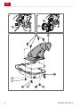
Montage Holmhalter (4)
Den Halter (4-1) anhand der bereits an der
Platte angebrachten 4 Schrauben (4-2), den
Unterlegscheiben (4-3) und Muttern (4-4) an
der Motorhacke montieren.
Die Kabeldurchführung (4-5) wie in der Abbil-
dung (4) montieren.
Montage Holm (5)
Die 2 Holmrohre (5-1) mittels Durchsteck-
schraube (5-2), Abstandsstück (5-3), Unter-
legscheiben (5-4) und Mutter (5-5) im oberen
Loch des Holms befestigen.
Dasselbe Verfahren für das Loch (5-9), in
dem man die andere Schraube (5-2), Ab-
standsstück (5-3) und die Unterlegscheibe 4
mm (5-6) in den Drehknopf (5-7) und den an-
deren Drehknopf (5-8) mit Mutter in der auf
der Abbildung (5) gezeigten Reihenfolge ein-
führt.
HINWEIS
Um ein Durchscheuern der Bowden-
züge zu vermeiden, Bowdenzüge zwi-
schen Durchsteckschrauben (5-2) und
Abstandsstück (5-3) durchführen!
Für weitere Informationen siehe Holm-
einstellung.
Montage Gashebel (6)
Das Gaskabel mit Schraube und Sechskant-
mutter am Holm befestigen.
Montage Steuerkabel (7)
Steuerkabel (7-1) mittles Schraube (7-2) am
rechten Holm (7-3) anschrauben.
ACHTUNG!
Den Holm (7-3) zwischen beiden Steuer-
kabeln durchführen.
INBETRIEBNAHME
Gerät erst in Betrieb nehmen, wenn die Montage
vollständig durchgeführt wurde.
ACHTUNG!
Vor der Erstinbetriebnahme Öl und Ben-
zin einfüllen. Dazu die mitgelieferte Be-
dienungsanleitung des Motorenherstel-
lers für den Benzinmotor beachten.
Einstellung Holm (5)
Die Holme sind höhenverstellbar.
1 Die Drehknöpfe (5-7) und (5-8) abschrau-
ben und die Durchsteckschraube (5-2) in das
Loch stecken, das am besten für Ihre Arbeit
geeignet ist.
Nur für die seitlich verstellbare Version:
2 Die Holme können durch Anheben des He-
bels (5-10) nach rechts oder links gedreht
werden.
Transportrad
Mit dem Transportrad die Motorhacke leicht und
bequem zum Einsatzort rollen.
1 Zum Arbeiten mit der Motorhacke das Trans-
portrad abnehmen. "Montage Transportrad
(3)"
Einstellung Bremssporn (2)
Damit die Motorhacke gut fräst und rich-
tig vorwärts arbeitet, lässt sich durch Locke-
rung der Feststellschraube (2-2) die Höhe
des Bremssporns (2-1) so einstellen, dass
die Maschine eine waagrechte Arbeitsposi-
tion beibehält.
Nach erfolgter Einstellung die Feststell-
schraube (2-2) anziehen.
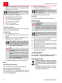
Starten des Motors (6)
Beim Starten des Motors darf der Kupplungshebel
für die Hackmesser nicht aktiviert sein!
1. Gashebel auf Position "START" stellen.
2. Starterseil zügig herausziehen und danach
langsam wieder aufrollen lassen.
Hackmesser einschalten (8)
1. Kupplungshebel ganz hochziehen und fest-
halten. Die Hackmesser dürfen sich erst nach
der Hälfte des Hebelweges beginnen zu dre-
hen.
Hackmesser ausschalten (8)
1. Kupplungshebel loslassen.
Rückwärtsgang einschalten (9)
1. Hebel für Rückwärtsgang bis zum Anschlag
hochziehen.
Rückwärtsgang ausschalten (9)
1. Hebel für Rückwärtsgang loslassen.
Motor ausschalten (6)
1. Gashebel auf Position "STOP" stellen.

Wartung und Pflege
441442_c 11
WARTUNG UND PFLEGE
ACHTUNG!
Verletzungsgefahr!
Vor allen Wartungs- und Pflegear-
beiten immer Motor abschalten und
den Zündkerzenstecker ziehen!
Motor kann nachlaufen. Nach Aus-
schalten vergewissern, dass Motor
steht!
Bei Wartungs- und Pflegearbeiten
am Schneidmesser immer Arbeits-
handschuhe tragen!
Das Gerät nach jedem Gebrauch reinigen
Gerät nicht mit Wasser abspritzen! Eindrin-
gendes Wasser (Zündanlage, Vergaser...)
kann zu Störungen führen.
HINWEIS
Wenn das Gerät zur Seite geneigt wird,
muss der Vergaser nach oben zeigen!
Fachmännische Überprüfung ist erforderlich:
nach Auffahren auf ein Hindernis
bei plötzlichem Stillstand des Motors
bei Getriebeschaden
bei defektem Keilriemen
bei verbogenem Messer
bei verbogener Motorwelle
Getriebeölwechsel
Grundsätzlich sollte alle 100 Arbeitsstunden auch
das Getriebeöl gewechselt werden. (Öl- Viskosi-
tät SAE 80).
Ölwechsel (10)
1. Ölverschlussschraube lösen.
2. Gerät schräg stellen und das Öl mit einer
Pumpe absaugen.
3. Neues Öl einfüllen. Erforderliche Ölmenge ca.
0,2 (MH4005) und 0,5 l (MH 5007 R).
HINWEIS
Die Maschine waagrecht stellen;
den Verschluss abschrauben und
überprüfen, dass das Öl am un-
teren Stand des Lochs ist. Der
Füll- und Entleerungsverschluss ent-
spricht dem Ölstand.
ACHTUNG!
Altöl nicht ins Kanalnetz oder Erd-
reich ablassen.
Grundwasserverschmutzung ist
strafbar.
Alle Tankstellen sind Altölannahme-
stellen oder informieren Sie sich bei
Ihrer kommunale Behörde.
4. Einfüllöffnung mit Verschlussschraube ver-
schließen.
Motor
Ölwechsel / Luftfilter / Zündkerze
Siehe Bedienungsanleitung des Motorenherstel-
lers.
Bowdenzüge nachstellen
Die Feineinstellung erfolgt durch die Stell-
schraube am Oberholm und an der Motorkonsole
(jeweils an den Bowdenzugenden).
1. Kontermuttern lösen.
2. mit Stellschraube nachjustieren.
HINWEIS
Richtige Einstellung: Die Hackmesser
dürfen sich erst nach der Hälfte des He-
belweges beginnen zu drehen.
3. Kontermuttern wieder festziehen.
Gaszug:
Siehe Bedienungsanleitung des Motorenherstel-
lers.
LAGERUNG
VORSICHT!
Brandgefahr!
Betankte Maschine nicht in Gebäuden
aufbewahren, in denen Benzindämpfe
mit offenem Feuer oder Funken in Be-
rührung kommen können!
HINWEIS
Reparaturen dürfen nur von autorisierten
Fachwerkstätten oder unserem Kunden-
dienst durchgeführt werden.
Motor ausschalten, Stillstand der Hackmes-
ser abwarten und Zündkerzenstecker abzie-
hen.
Bei Tätigkeiten an den Hackmessern immer
Schutzhandschuhe tragen.
Benzintank nur im Freien entleeren.

D
Lagerung
12 MH 4005 / MH 5007 R
Den Motor ausschalten und abkühlen lassen,
bevor der Tankverschluss abgenommen wird
Gerät nicht mit Wasser abspritzen! Eindrin-
gendes Wasser kann den Motor und den Si-
cherheits-Tastschalter zerstören.
ZUBEHÖRTEILE
An Stelle des Bremsspornes können verschie-
dene Zubehörteile angebaut werden. Fragen Sie
Ihren Fachhändler.
ENTSORGUNG
Ausgediente Geräte, Batterien oder
Akkus nicht über den Hausmüll ent-
sorgen!
Verpackung, Gerät und Zubehör sind aus
recyclingfähigen Materialien hergestellt
und entsprechend zu entsorgen.
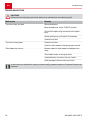
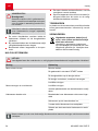
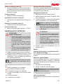
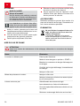
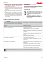
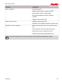
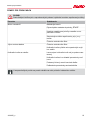
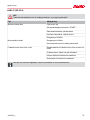
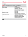
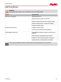
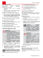
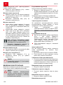
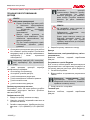
HILFE BEI STÖRUNGEN
ACHTUNG!
Vor allen Wartungs- und Reinigungsarbeiten Zündkerzenstecker abziehen!
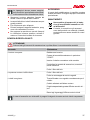
Störung Beseitigung
Benzin auftanken
Gashebel auf Position "START" stellen
Zündkerzenstecker auf die Zündkerze aufstecken
Zündkerze überprüfen, eventuell erneuern
Motor springt nicht an
Luftfilter reinigen
Luftfilter reinigenMotorleistung lässt nach
Hackmesser von verrotteten Pflanzenresten rei-
nigen
Bowdenzug für Hackmesser nicht richtig einge-
stellt
Hackmesser auf der Getriebewelle lose
Keilriemen defekt Kundendienst-Werkstatt
Hackmesser drehen nicht
Getriebeschaden Kundendienst-Werkstatt
HINWEIS
Bei nicht behebbaren Störungen wenden Sie sich bitte an unseren zuständigen Kundendienst.

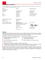
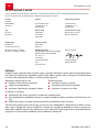
EG-Konformitätserklärung
441442_c 13
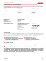
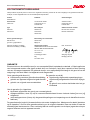
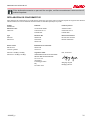
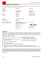
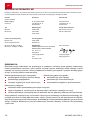
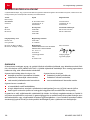
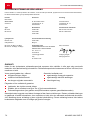
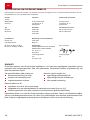
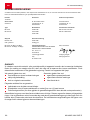
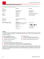
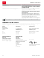
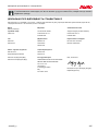
EG-KONFORMITÄTSERKLÄRUNG
Hiermit erklären wir, dass dieses Produkt in der von uns in Verkehr gebrachten Ausführung, den Anforderungen der harmonisierten EU-
Richtlinien, EU-Sicherheitsstandards und den produktspezifischen Standards entspricht.
Produkt
Motorhacke
Hersteller Bevollmächtigter
Seriennummer
G2021012
AL-KO Geräte GmbH
Ichenhauser Str. 14
D-89359 Kötz
Andreas Hedrich
Ichenhauser Str. 14
D-89359 Kötz
Typ EU-Richtlinien Harmonisierte Normen
MH 4005
MH 5007 R
2006/42 EG
2014/30/EU
2000/14/EG
EN 709:1997+A4:2009
EN ISO 14982:2009
Schallleistungspegel Konformitätsbewertung
EN ISO 3744
gemessen / garantiert
2000/14/EG
Anhang VII
MH 4005: 92 dB(A) / 93 dB(A)
MH 5007 R: 89 dB(A) / 93 dB(A)
Benannte Stelle
ORGANISMO NOTIFICATO SECONDO
REGGIO EMILIA INNOVAZIONE
Soc. Cons. a r.l.
Via Sicilia 31
41122 Reggio Emilia
Italy
Nr. Instituo 1232
Kötz, 20.06.2016
Wolfgang Hergeth
Managing Director
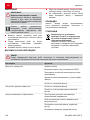
GARANTIE
Etwaige Material- oder Herstellungsfehler am Gerät beseitigen wir während der gesetzlichen Verjäh-
rungsfrist für Mängelansprüche entsprechend unserer Wahl durch Reparatur oder Ersatzlieferung. Die
Verjährungsfrist bestimmt sich jeweils nach dem Recht des Landes, in dem das Gerät gekauft wurde.
Unsere Garantiezusage gilt nur bei:
beachten dieser Bedienungsanleitung
sachgemäßer Behandlung
verwenden von Original-Ersatzteilen
Die Garantie erlischt bei:
eigenmächtigen Reparaturversuchen
eigenmächtigen technischen Veränderungen
nicht bestimmungsgemäßer Verwendung
Von der Garantie ausgeschlossen sind:
Lackschäden, die auf normale Abnutzung zurückzuführen sind
Verschleißteile, die auf der Ersatzteilkarte mit Rahmen [xxx xxx (x)] gekennzeichnet sind
Verbrennungsmotoren (hier gelten die Garantiebestimmungen der jeweiligen Motorenhersteller)
Die Garantiezeit beginnt mit dem Kauf durch den ersten Endabnehmer. Maßgebend ist das Datum auf
dem Kaufbeleg. Wenden Sie sich bitte mit dieser Erklärung und dem Original-Kaufbeleg an Ihren Händ-
ler oder die nächste autorisierte Kundendienststelle. Die gesetzlichen Mängelansprüche des Käufers
gegenüber dem Verkäufer bleiben durch diese Erklärung unberührt.

en
Original instructions for use
14 MH 4005 / MH 5007 R
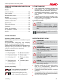
ORIGINAL INSTRUCTIONS FOR USE
Contents
About this handbook........................................ 14
Product description.......................................... 14
Safety instructions............................................14
Assembly..........................................................15
Startup..............................................................16
Maintenance and care..................................... 16
Storage.............................................................17
Accessory parts................................................17
Disposal............................................................17
Troubleshooting................................................18
EU declaration of conformity............................19
Guarantee.........................................................19
ABOUT THIS HANDBOOK
Read this documentation before starting up
the machine. This is a precondition for safe
working and flawless operation.
Observe the safety warnings in this docu-
mentation and on the product.
This documentation is a permanent integral
part of the product described and must be
passed on to the new owner if the product is
sold.
Explanation of symbols
CAUTION!
Following these safety warnings care-
fully can prevent personal injury and/or
material damage.
ADVICE
Special instructions for greater ease of
understanding and improved handling.
PRODUCT DESCRIPTION
Designated use
This device is only intended for use on pre-culti-
vated soil.
This device is not suitable for use on solid soil,
e.g. compacted turf.
The continued use of this device with original
spare parts is only allowed in accordance with
their purpose. Any other use is not permitted.
Product overview
1 Throttle lever 6 Depth skid
2 Transport wheel 7 Clutch lever
3 Tiller blades 8 Reverse lever
4 Guard plate ex-
tension
9 Protective discs
5 Starter cable
Symbols on the machine
Before starting operation, read the
operating instructions!
Rotating tool! Keep your hands
and feet away!
SAFETY INSTRUCTIONS
WARNING!
Fire danger! Petrol is highly flammable!
WARNING!
Risk of poisoning!
CAUTION!
Danger of burns!
The exhaust as well as the area surroun-
ding it can heat up to 80°.
CAUTION!
Always perform a visual check prior to
start-up.
Young people under 16 years of age, and
people who do not know the instructions for
use, are not allowed to use the machine.
The device should not be used on rocky ter-
rain.
Comply with local regulations on the mini-
mum age of people operating the equipment.
Do not wear loose or baggy clothes
Wear sturdy, non-slip footwear
Remove foreign objects from the working
area.

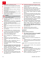
Safety instructions
441442_c 15
The machine is not allowed to be used in
commercial applications
The machine must not be operated if the ope-
rator is under the influence of alcohol, drugs
or medication.
Comply with working time regulations in force
in your country.
Work only when there is adequate daylight or
artificial lighting.
CAUTION!
Always perform a visual check prior to
start-up.
The equipment should be used only if in good
order and condition
Note that the user is responsible for accidents
and damage caused to other persons and/or
their property
Do not disable safety and protective devices.
Do not place your hands and feet close to any
rotating parts.
Never lift or carry the mower while the motor
is running
Always ensure stability when working.
The user is responsible for accidents invol-
ving other people and their property.
Do not leave the appliance unsupervised.
Keep the exhaust and motor clean
Store petrol in designated containers only.
Only refuel in open air.
Replace a damaged petrol tank and/or tank
cap.
Only replace damaged or worn parts by ge-
nuine spare parts.
Subject to changes in design and configura-
tion.
No one should be standing in front of the de-
vice and/or tiller blades when starting the mo-
tor - the tiller blade drive must be turned off.
When attaching and removing the transport
wheel and/or when adjusting the depth skid,
the motor must be turned off and the tiller bla-
des must be upright.
When moving the device using the attached
transport wheel, turn off the motor and wait
for the tiller blades to come to a standstill.
The device may only be operated by main-
taining the safety distance provided by the
handlebar.
Always operate parallel to the slope.
Do not operate the device up or down the
slope, as well as on slopes with a gradient of
more than 10°.
Do not open the tank cap or refuel with petrol
while the motor is still running and while the
machine is still hot.
Use a funnel or a filler pipe when refuelling so
that no fuel is spilled on the engine, the deck
or the ground.
Do not start the engine if petrol has over-
flowed. The appliance may be cleaned, and
any attempt at ignition may be made, only
when the petrol vapours have dissipated.
For safety reasons, never use the engine with
worn or damaged parts. Such parts must al-
ways be replaced, not repaired. Use OEM
spare parts. Spare parts of inferior quality can
damage the engine and endanger your safety
Renew exhaust silencers if damaged.
Do not change the engine governor settings.
ASSEMBLY
Assembly of depth skid (2)
Insert the long side of the depth skid (2-1) into
the end piece of the frame arm and lock it by
turning the handle (2-2).
Assembly of transport wheel (3)
The transport wheel (3-1) is used to transport the
cultivator.
Push the transport wheel (3-1) onto the depth
skid and secure it using the star screw (3-2).
Remove the transport wheel during operation:
Loosen the wing screw (3-2) and remove the
transport wheel.
Assembly of handlebar support (4)
Attach the support (4-1) to the cultivator using
the 4 screws (4-2) already positioned on the
plate along with the washers (4-3) and nuts
(4-4).
Attach the cable feed-through (4-5) as shown
in the figure (4).

en
Assembly
16 MH 4005 / MH 5007 R
Fitting the handlebar (5)
Fasten the 2 handlebars (5-1) to support
by inserting the through screw (5-2), spacer
(5-3), washers (5-4) and nut (5-5) in the up-
per hole of the handlebar.
Proceed in the same way for the lower hole
(5-9), by fitting the other screw (5-2), spacer
(5-3) and the washers h.4 (5-6) in the knob
(5-7) and knob (5-8) complete with nut, in the
sequence shown in the illustration (5).
ADVICE
To prevent fraying the Bowden cables,
guide the Bowden cables between the
through bolts (5-2) and spacers (5-3)!
For more information, see Setting the
handlebar.
Assembly of throttle lever (6)
Secure the throttle cable to the handlebars
using a screw and hexagon nut.
Assembly of control cable (7)
Secure the control cable (7-1) to the right
handlebar (7-3) using a screw (7-2).
CAUTION!
Guide the handlebar (7-3) between both
control cables.
STARTUP
Only start up the machine, after assembly is fully
completed.
CAUTION!
Fill with oil and petrol before initial start-
up. For this purpose, consult the sup-
plied operating instructions from the pe-
trol motor manufacturer.
Setting the handlebar (5)
The handlebars are height-adjustable.
1 Unscrew knobs (5-7) and (5-8), and insert the
through bolt (5-2) into the hole that best suits
your working requirements.
For side-adjustable version only:
2 The handlebars can be turned right or left by
lifting the lever shown in (5-10).
Transport wheel
The cultivator can be easily rolled to the place of
operation using the transport wheel.
1 The transport wheel should be removed
when operating the cultivator. "Assembly of
transport wheel (3)"
Depth skid setting (2)
To ensure that the cultivator properly tills and
moves properly forward, the height of the
depth skid (2-1) should be set via the fixing
screw (2-2) so that the machine maintains a
level operating position.
Once set to the correct position, tighten the
fixing screw (2-2).
Starting the motor (6)
When starting the motor, the tiller blade clutch le-
ver may not be activated.
1. Move the throttle lever to the "START" posi-
tion.
2. Pull out the cable starter briskly, and then al-
low it to wind back in slowly.
Switching on the tiller blades (8)
1. Push clutch lever up fully and hold it there.
The tiller blades may begin to turn when the
lever is only pressed halfway up.
Switching off the tiller blades (8)
1. Release the clutch lever.
Switch on the reverse gear (9)
1. Pull up the reverse gear lever up to the stop.
Switching off the reverse gear (9)
1. Release the reverse gear.
Switching off the motor (6)
1. Move throttle lever to the "STOP".
MAINTENANCE AND CARE
CAUTION!
Risk of injury!
Always switch the motor off and pull
the spark plug connector prior to any
maintenance and care work.
Motor may continue running. Make
sure that the motor has stopped af-
ter switching it off.
Always wear work gloves when car-
rying out maintenance and care jobs
on the cutting blade.

Maintenance and care
441442_c 17
Clean the appliance after every use
Do not spray the machine with water! Pene-
trating water (ignition system, carburettor...)
can lead to malfunctions.
ADVICE
When the device is tilted to the side, the
carburettor must be pointing upwards.
Expert inspection is required:
After running into an obstacle
If the motor stops suddenly
If there is gear damage
If the V-belt is defective
If a blade is bent
If the motor shaft is bent
Changing the gear oil
In general, the gear oil should be changed every
100 operating hours. (oil viscosity SAE 80).
Oil change (10)
1. Remove the oil drain plug.
2. Set the machine at an angle and suction off
the oil via a pump.
3. Fill with new oil. Required oil quantity approx.
0.2 (MH4005) and 0.5 l (MH 5007 R).
ADVICE
Set the machine upright; open the
cap and check to ensure that the oil
is at the bottom level of the hole. The
filling and emptying cap corresponds
to the oil level.
CAUTION!
The used oil must not be drained into
the sewer system or into the ground.
Contaminating the ground water is a
punishable offence.
Most petrol stations will dispose of
your waste oil or please contact your
local authority for more information.
4. Close the fill opening using the screw plug.
Motor
Oil change / Air filter / Spark plug
See the instructions for use from the motor manu-
facturer.
Adjusting Bowden cables
The fine adjustment is made using the adjusting
screw on the upper handle and on the motor
mount (on the ends of the Bowden cables).
1. Loosen the locknuts.
2. Adjust via the adjusting screw.
ADVICE
Correct set-up: The tiller blades may
begin to turn when the lever is only pres-
sed halfway up.
3. Re-tighten the locknuts.
Throttle cable:
See the instructions for use from the motor manu-
facturer.
STORAGE
CAUTION!
Fire hazard!
Do not store fuelled machine in buildings
where the petrol fumes might come into
contact with naked flames or sparks!
ADVICE
Only authorized specialized workshops
or our customer service are allowed to
repair the unit.
Switch off motor, wait for the tiller blades to
come to a standstill and disconnect the spark
plug connector.
Always wear protective gloves when working
on the tiller blades.
Only drain the petrol tank outdoors.
Switch off the engine and allow to cool down
before removing the tank cap
Do not spray the machine with water! Water
ingress can cause irreparable damage to the
motor and the safety pushbutton switch.
ACCESSORY PARTS
Several different accessory parts can be attached
to the location of the depth skid. Ask your specia-
list dealer about this.
DISPOSAL
Do not dispose of worn-out machines
or spent batteries (including recharge-
able batteries) in domestic waste!
The packaging, machine and accessories
are made from recyclable materials, and
must be disposed of accordingly.

en
Troubleshooting
18 MH 4005 / MH 5007 R
TROUBLESHOOTING
CAUTION!
Disconnect the spark plug connector before any maintenance and cleaning work!
Malfunction Remedy
Refuel with petrol
Move throttle lever to the "START" position
Connect the spark plug connector to the spark
plug
Check spark plug, and replace if necessary
The motor does not start
Clean the air filter
Clean the air filterThe motor loses power
Clean the tiller blades of decaying plant residue
Bowden cable for tiller blades not adjusted cor-
rectly
Tiller blades loose on the gear shaft
V-belt defective Customer Service Centre
Tiller blades do not turn
Gear damage Customer Service Centre
ADVICE
In the event of a malfunction that you cannot rectify, please contact our Customer Service de-
partment.

EU declaration of conformity
441442_c 19
EU DECLARATION OF CONFORMITY
We hereby declare that this product, in the version placed on the market by us, complies with the requirements of the harmonised EU Di-
rectives, EU safety standards and the product-specific standards.
Product
Cultivator
Manufacturer Duly authorised person
Serial number
G2021012
AL-KO Geräte GmbH
Ichenhauser Str. 14
D-89359 Kötz
Andreas Hedrich
Ichenhauser Str. 14
D-89359 Kötz
Type EU Directives Harmonised standards
MH 4005
MH 5007 R
2006/42 EC
2014/30/EU
2000/14/EC
EN 709:1997+A4:2009
EN ISO 14982:2009
Sound power level Conformity evaluation
EN ISO 3744
measured / guaranteed
2000/14/EC
Annex VII
MH 4005: 92 dB(A) / 93 dB(A)
MH 5007 R: 89 dB(A) / 93 dB(A)
Conformity evaluation
ORGANISMO NOTIFICATO SECONDO
REGGIO EMILIA INNOVAZIONE
Soc. Cons. a r.l.
Via Sicilia 31
41122 Reggio Emilia
Italy
Nr. Instituo 1232
Kötz, 20.06.2016
Wolfgang Hergeth
Managing Director
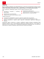
GUARANTEE
We will resolve any material or manufacturing faults on the machine during the legal warranty period
for claims relating to faults, in accordance with our choice either to repair or replace. The legal warranty
period is determined by the legislation of the country in which the machine was purchased.
Our warranty promise applies only if:
these operating instructions are complied with
the appliance is handled correctly
original spare parts have been used
The warranty becomes void if:
unauthorised repair attempts
unauthorised technical modifications
non-intended use
The guarantee excludes:
Paint damage that can be attributed to normal wear and tear
Wear parts that are marked with a frame on the spare parts card: [xxx xxx (x)]
Internal combustion engines (these are covered by the warranty provisions of the corresponding
engine manufacturers).
The guarantee period commences with purchase by the first end user. The date on the proof of purchase
is decisive. In the event of a warranty claim, please take this warranty declaration and the original proof
of purchase, and contact your dealer or the nearest authorised customer service centre. This statement
does not affect the purchaser's statutory claims for defects against the vendor.

nl
Originele gebruikershandleiding
20 MH 4005 / MH 5007 R
ORIGINELE
GEBRUIKERSHANDLEIDING
Inhoudsopgave
Over dit handboek............................................20
Productbeschrijving.......................................... 20
Veiligheidsvoorschriften....................................20
Montage............................................................21
Inbedrijfstelling..................................................22
Onderhoud........................................................23
Opslag.............................................................. 24
Toebehoren.......................................................24
Verwijderen.......................................................24
Hulp bij storingen............................................. 24
EG-conformiteitsverklaring............................... 25
Garantie............................................................25
OVER DIT HANDBOEK
Lees deze documentatie vóór ingebruikname
door. Dit is een voorwaarde voor veilig wer-
ken en storingsvrij gebruik.
Neem de veiligheidsvoorschriften en waar-
schuwingen in deze documentatie en op het
product in acht.
Deze documentatie is permanent onderdeel
van het beschreven product en dient bij ver-
koop aan de koper te worden overgedragen.
Legenda
LET OP!
Het nauwkeurig in acht nemen van deze
waarschuwingen kan verwondingen en/
of materiële schade voorkomen.
ADVICE
Speciale aanwijzingen voor een beter
begrip en gebruik.
PRODUCTBESCHRIJVING
Reglementair gebruik
Dit apparaat is slechts bedoeld voor de bewerking
van op voorhand losgewoelde grond.
Dit apparaat is niet geschikt voor de verwerking
van vaste grond, bijv. een vast aangestampt ga-
zon.
Verder gebruik van dit apparaat met originele aan-
vullingen is slechts toegestaan voor de vastge-
stelde doelen. Een ander gebruik is niet toeges-
taan.
Productoverzicht
1 Gashendel 6 Remsteun
2 Transportwiel 7 Koppelingshen-
del
3 Hakmessen 8 Hendel voor ach-
teruitversnelling
4 Veiligheidsplaat 9 Bescherming pla-
ten
5 Startkoord
Symbolen op het apparaat
Lees voor de ingebruikname de
gebruikershandleiding door!
Roterend apparaat! Blijf met uw
handen en voeten uit de buurt!
VEILIGHEIDSVOORSCHRIFTEN
WAARSCHUWING!
Brandgevaar! Benzine is sterk ontvlam-
baar!
WAARSCHUWING!
Vergiftigingsgevaar!
De motor nooit in afgesloten ruimten la-
ten lopen.
LET OP!
Risico op brandwonden!
De uitlaat en de delen in de nabijheid van
de uitlaat kunnen een temperatuur van
80° hebben.
LET OP!
Voor inbedrijfstelling altijd een visuele in-
spectie uitvoeren.
Jongeren onder de leeftijd van 16 jaar en per-
sonen die de gebruikershandleiding niet heb-
ben gelezen, mogen het apparaat niet gebrui-
ken.
La page charge ...
La page charge ...
La page charge ...
La page charge ...
La page charge ...
La page charge ...
La page charge ...
La page charge ...
La page charge ...
La page charge ...
La page charge ...
La page charge ...
La page charge ...
La page charge ...
La page charge ...
La page charge ...
La page charge ...
La page charge ...
La page charge ...
La page charge ...
La page charge ...
La page charge ...
La page charge ...
La page charge ...
La page charge ...
La page charge ...
La page charge ...
La page charge ...
La page charge ...
La page charge ...
La page charge ...
La page charge ...
La page charge ...
La page charge ...
La page charge ...
La page charge ...
La page charge ...
La page charge ...
La page charge ...
La page charge ...
La page charge ...
La page charge ...
La page charge ...
La page charge ...
La page charge ...
La page charge ...
La page charge ...
La page charge ...
La page charge ...
La page charge ...
La page charge ...
La page charge ...
La page charge ...
La page charge ...
La page charge ...
La page charge ...
La page charge ...
La page charge ...
La page charge ...
La page charge ...
La page charge ...
La page charge ...
La page charge ...
La page charge ...
La page charge ...
La page charge ...
La page charge ...
La page charge ...
La page charge ...
La page charge ...
La page charge ...
La page charge ...
La page charge ...
La page charge ...
La page charge ...
La page charge ...
La page charge ...
La page charge ...
La page charge ...
La page charge ...
La page charge ...
La page charge ...
La page charge ...
La page charge ...
La page charge ...
La page charge ...
La page charge ...
La page charge ...
-
 1
1
-
 2
2
-
 3
3
-
 4
4
-
 5
5
-
 6
6
-
 7
7
-
 8
8
-
 9
9
-
 10
10
-
 11
11
-
 12
12
-
 13
13
-
 14
14
-
 15
15
-
 16
16
-
 17
17
-
 18
18
-
 19
19
-
 20
20
-
 21
21
-
 22
22
-
 23
23
-
 24
24
-
 25
25
-
 26
26
-
 27
27
-
 28
28
-
 29
29
-
 30
30
-
 31
31
-
 32
32
-
 33
33
-
 34
34
-
 35
35
-
 36
36
-
 37
37
-
 38
38
-
 39
39
-
 40
40
-
 41
41
-
 42
42
-
 43
43
-
 44
44
-
 45
45
-
 46
46
-
 47
47
-
 48
48
-
 49
49
-
 50
50
-
 51
51
-
 52
52
-
 53
53
-
 54
54
-
 55
55
-
 56
56
-
 57
57
-
 58
58
-
 59
59
-
 60
60
-
 61
61
-
 62
62
-
 63
63
-
 64
64
-
 65
65
-
 66
66
-
 67
67
-
 68
68
-
 69
69
-
 70
70
-
 71
71
-
 72
72
-
 73
73
-
 74
74
-
 75
75
-
 76
76
-
 77
77
-
 78
78
-
 79
79
-
 80
80
-
 81
81
-
 82
82
-
 83
83
-
 84
84
-
 85
85
-
 86
86
-
 87
87
-
 88
88
-
 89
89
-
 90
90
-
 91
91
-
 92
92
-
 93
93
-
 94
94
-
 95
95
-
 96
96
-
 97
97
-
 98
98
-
 99
99
-
 100
100
-
 101
101
-
 102
102
-
 103
103
-
 104
104
-
 105
105
-
 106
106
-
 107
107
-
 108
108


AL-KO MH 4005 Petrol Manuel utilisateur
- Taper
- Manuel utilisateur
- Ce manuel convient également à
dans d''autres langues
- slovenčina: AL-KO MH 4005 Petrol Používateľská príručka
- dansk: AL-KO MH 4005 Petrol Brugermanual
- svenska: AL-KO MH 4005 Petrol Användarmanual

