DIODE LED LO-PRO Junction Box for MikroDIM - NEMA 1 Guide d'installation
- Taper
- Guide d'installation

DRY LOCATION
1 OF 4
INSTALLATION GUIDE
LO-PRO JUNCTION BOX FOR MIKRODIM
LO-PRO JUNCTION BOX FOR MIKRODIM INSTALLATION GUIDE
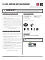
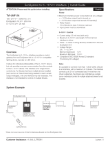
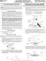
IMPORTANT SAFETY INSTRUCTIONS SUPPLIED ACCESSORIES
INSTALLATION
A. Mikro Juncon Box (1)
B. Driver Mounng Bracket (1)
C. Ground Screw (1)
D. Cover Screws (2)
E. Mounng Screws (4)
F. Wire Connector 22-14AWG
(600V) (6)
G. NM (Non-Metallic) Cable
Strain Relief (2) - 1/2”
A. B.
C. D. E.
1. Read all instrucons.
2. Install in accordance with naonal and local electrical code regulaons.
3. This product is intended to be installed and serviced by a qualied, licensed
electrician.
4. For cabinet and surface mount use only.
5. Do not install outdoors or in wet locaons. For indoor and dry use only.
6. Do not conceal or extend exposed conductors through a building wall.
7. For low voltage exposed insulated conductor systems required by 30.1(c) of
UL 2108 do not install any part of this system less than 7 feet (2.2m) above
the oor.
8. To reduce the risk of re and burns, do not install this lighng system where
the exposed bare conductors can be shorted or contact any conducve
materials.
9. To reduce the risk of re and overheang, make sure all connecons are ght.
10. Do not install any luminaire closer than 6 inches (15.25cm) from any curtain,
or similar combusble materials.
11. Turn o electrical power before modifying the lighng system in any way. F.
SAVE THESE INSTRUCTIONS
DO NOT CONNECT DIRECTLY TO HIGH VOLTAGE POWER!
Read all warnings and installaon instrucons thoroughly.
WARNING
WARNING! ALWAYS TURN OFF MAIN POWER BEFORE INSTALLING & SERVICING!
Ensure to read all Safety and Installaon Instrucons thoroughly!
Power Supply/LED Driver Sold Separately.
1
TURN POWER OFF AT CIRCUIT BREAKER
SHOCK HAZARD! May result in serious injury or death.
Turn power OFF at circuit breaker prior to installaon.
G.
CONSIGNES DE SÉCURITÉ IMPORTANTES
1. Lisez toutes les instrucons
2. Installez conformément à la réglementaon du code électrique naonal et
local.
3. Ce produit est desné à être installé et entretenu par un électricien agréé
qualié.
4. Pour armoire et montage en surface ulizer seulement.
5. Ne pas installer à l’extérieur ou dans des endroits humides. Pour une
ulisaon en intérieur et sec seulement.
6. Ne pas cacher ou allonger des conducteurs exposés à travers un mur de
bâment.
7. Pour la basse exposée tension systèmes de conducteurs isolés requis par
30.1 (c) de la norme UL 2108 ne pas installer une pare de ce système moins
de 7 pieds (2.2m) au-dessus du sol.
8. Pour réduire le risque d’incendie et de brûlures, ne pas installer ce système
d’éclairage où les conducteurs nus exposés peuvent être court-circuités ou
communiquer avec tous les matériaux conducteurs.To reduce the risk of re
and overheang, make sure all connecons are ght.
9. Pour réduire le risque d’incendie et de surchaue, assurez-vous que toutes
les connexions sont bien serrées.
10. 10. Ne pas installer un luminaire à moins de 6 pouces (15,25 cm) de toute
rideau, ou matériaux combusbles analogues.
11. Coupez l’alimentaon électrique avant de évoluer le système d’éclairage en
aucune façon.
CONSERVER CES INSTRUCTIONS

2 OF 4
LO-PRO JUNCTION BOX FOR MIKRODIM INSTALLATION GUIDE
2
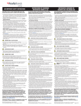
DETERMINE LOCATION TO INSTALL COMPONENTS
1) Mikro Driver
& Juncon Box
2) Control 3) Fixture
Refer to SYSTEM DIAGRAM under step 7. Ensure to calculate
LED load properly for loading LED driver. See LED luminaire
installaon guide for calculang loads.
WIRE GAUGE & VOLTAGE DROP
Ensure applicable wire is installed between driver, xture, and any
controls in between. When choosing wire, factor in voltage drop,
amperage rang, and type (in-wall rated, wet locaon rated, etc.)
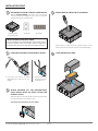
MOUNT BOX TO SURFACE WITH 4X SCREWS.
3
PUNCH OUT KNOCKOUTS FOR CONDUIT ACCESS
4
ATTACH INCLUDED 1/2” NM (NON-METTALIC)
CABLE STRAIN RELIEF OR OTHER FITTING FOR
CONDUIT ACCESS.
Addional ngs for BX cable, exible conduit and rigid conduit
must be purchased at local hardware store.
J-Box actual inner KO diameter ts 1/2” ngs.
a. Use punch and hammer to loosen
appropriate K/O. (Inner K/O for 1/2”
ngs)
b. Grip K/O with pliers.
Bend back and forth
unl broken o.
5
PLACE DRIVER INTO J-BOX.
6
Mount J-Box to a sturdy surface in a posion where it can be
easily located and accessed for servicing and troubleshoong.
INSTALLATION CONT.

3 OF 4
LO-PRO JUNCTION BOX FOR MIKRODIM INSTALLATION GUIDE
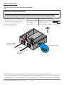
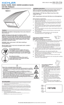
Wire Combinaon Range Wire Combinaon Range (mm)
600V Max
22 to 14 AWG
Min. (1) #18 & (2) #20
Max. (2) # 14
600V Max
0.34mm2 to 2.5mm2
Min. (1) 0.75mm2 w/ (1) 0.50mm2
Max. (4) 1.5mm2 w/ (1) 0.50mm2
1. GND*: Aach to J-Box and to Primary Ground
2. Neutral: To Primary High Voltage Neutral
3. Line (Hot): To Primary High Voltage Line Hot
4. V+: To Low Voltage Load V+
5. V−: To Low Voltage Load V−
WARNING! SYSTEM DIAGRAM NOTE!
Each compable LED driver has a unique System Diagram and color-coded wires. Please see each LED driver, luminaire
(tape light, puck light, etc.), and control installaon guide for System Diagrams, connecons and wire colors. Pictured
below is a Tradional ON/OFF Switching system. This is for reference only and does not apply to every driver.
Wire LED Driver. Ensure main power is OFF.
HIGH VOLTAGE
AC INPUT
OUTPUT TO LOW
VOLTAGE LED LOAD
Line (Hot)
Neutral
WIRE DRIVER TO AC INPUT AND LOW VOLTAGE LOAD.
7
INSTALLATION CONT.
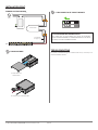
LED Driver and J-Box must be grounded in accordance with local and naonal electrical codes. Ground the LED
Driver and J-Box with the included Green Grounding Screw. Some compable LED drivers are Class II cered and do
not require a FG (Fault Ground Connecon). Refer to the LED driver label and installaon guide for more informaon.
*
3/8 in. (10 mm)
V-
V+ Grounding Screw*

4 OF 4
LO-PRO JUNCTION BOX FOR MIKRODIM INSTALLATION GUIDE
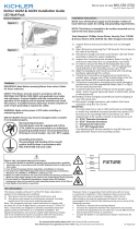
FINISH ASSEMBLY.
8
a. Slide cover into
Juncon Box
b. Fasten cover to Juncon Box.
INSTALLATION CONT.
9
Install applicable
wire gauge / type
AC Power
50/60Hz
N
L
L
N
GND
LED Tape Light / Fixture
V-
V+
120VAC Dimmer
12VDC / 24VDC
V+
V-
L
N
DIMMER SYSTEM DIAGRAM TURN POWER ON AT CIRCUIT BREAKER.
SYSTEM WORKING IMPROPERLY?
Turn power OFF at circuit breaker and verify all connecons.
Review SYSTEM DIAGRAMS and TROUBLESHOOTING on LED Driver,
Luminaire, and Control Installaon Guides.
TROUBLESHOOTING
For System Troubleshoong see individual LED Driver, Luminaire, and
Control Installaon Guides.
-
 1
1
-
 2
2
-
 3
3
-
 4
4


DIODE LED LO-PRO Junction Box for MikroDIM - NEMA 1 Guide d'installation
- Taper
- Guide d'installation
dans d''autres langues
Documents connexes

Autres documents
-
 Lutron Electronics TVI-LMF-2A Install Manual
-
 Acuity Brands Lighting Lithonia Lighting LIL LED 30K MVOLT Manuel utilisateur
-
Eaton Portfolio LDRT812B Installation Instructions Manual
-
Cooper Lighting LDSQ4B LED Housing LED Reflector Downlight Reflector Manuel utilisateur
-
 Kichler Lighting 16236AZT50 Manuel utilisateur
-
-
 Kichler Lighting 16232AZT30 Manuel utilisateur
-
 Commercial Electric CER608941WH30 Guide d'installation
-
 Steris Harmony Vled Surgical Lighting System Mode d'emploi


