Jenn-Air JB36NXFXRE Manuel utilisateur
- Catégorie
- Frigos
- Taper
- Manuel utilisateur
Ce manuel convient également à

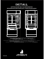
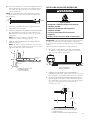
iNstaLl
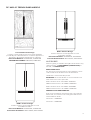
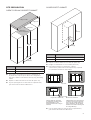
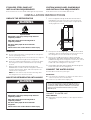
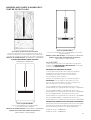
BOTTOM MOUNT BUILTIN REFRIGERATOR
RÉFRIGÉRATEUR ENCASTRÉ AVEC CONGÉLATEUR EN BAS
For questions about features, operation/performance, parts, accessories, or service, call:
1-800-JENNAIR (1-800-536-6247) or visit our website at www.jennair.com.
In Canada, call: 1-800-JENNAIR (1-800-536-6247), or visit our website at www.jennair.ca.
Pour des questions à propos des caractéristiques, du fonctionnement/rendement, des pièces, accessoires ou service, composer le:
1800JENNAIR (1800536-6247) ou visiter notre site Web au www.jennair.com.
Au Canada, composer le: 1800JENNAIR (1800536-6247) ou visiter notre site Web au www.jennair.ca.
W11511880B

2
TABLE OF CONTENTS
INTRODUCTION
Refrigerator Safety ......................................................................................3
VARIANTS AND ACCESSORIES
36" Single-Door Models ..........................................................................4
36" and 42" French Door Models ......................................................5
INSTALLATION REQUIREMENTS
Tools and Parts ...............................................................................................6
Product Dimensions ..................................................................................7
Door Swing Dimensions .........................................................................8
Site Preparation .............................................................................................9
Location Requirements ...........................................................................11
Water Supply Requirements ................................................................11
Electrical Requirements ..........................................................................12
Stainless Steel Panel Kit
Installation Requirements .....................................................................13
Custom Wood Panel Dimensions and Installation
Requirements .................................................................................................13
INSTALLATION INSTRUCTIONS
Unpack the Refrigerator .........................................................................13
Move the Refrigerator into House ....................................................13
Connect the Water Supply ....................................................................13
Plug in Refrigerator ....................................................................................16
Install Side Trims ...........................................................................................16
Move Refrigerator to Final
Location ..............................................................................................................16
Level and Align Refrigerator ................................................................17
Install Base Grille ..........................................................................................18
Complete Installation ................................................................................ 18
TABLE DES MATIÈRES
INTRODUCTION
Sécurité du réfrigérateur ........................................................................19
VARIANTES ET ACCESSOIRES
Modèles avec porte simple de 36po ..............................................20
Modèles avec porte à double battant de 36po et 42po ......21
EXIGENCES D’INSTALLATION
Outils et pièces ..............................................................................................22
Dimensions du produit ............................................................................23
Dimensions pour l’ouverture desportes .....................................24
Préparation du site ......................................................................................25
Exigences d’emplacement ....................................................................27
Spécifications de l’alimentation eneau .......................................27
Spécificationsélectriques ......................................................................28
Exigences d’installation de l’ensemble de panneaux
enacierinoxydable .....................................................................................29
Exigences d’installation et dimensions des panneaux
deboispersonnalisés ................................................................................29
INSTRUCTIONS D’INSTALLATION
Déballage du réfrigérateur ...................................................................29
Déplacement du réfrigérateur dans le domicile ...................29
Raccordement à la canalisation d’eau ..........................................29
Brancher le réfrigérateur ........................................................................32
Installation des garnitures latérales ................................................32
Déplacement du réfrigérateur à son emplacement
définitif ................................................................................................................32
Réglage de l’aplomb et alignement du réfrigérateur ........33
Installation de la grille de la base ......................................................34
Terminer l’installation ................................................................................34

3
INTRODUCTION
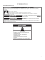
REFRIGERATOR SAFETY
You can be killed or seriously injured if you don't immediately
You can be killed or seriously injured if you don't follow
All safety messages will tell you what the potential hazard is, tell you how to reduce the chance of injury, and tell you what can
happen if the instructions are not followed.
Your safety and the safety of others are very important.
We have provided many important safety messages in this manual and on your appliance. Always read and obey all safety
messages.
This is the safety alert symbol.
This symbol alerts you to potential hazards that can kill or hurt you and others.
All safety messages will follow the safety alert symbol and either the word “DANGER” or “WARNING.”
These words mean:
follow instructions.
instructions.
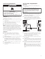
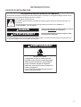
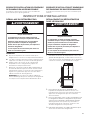
DANGER
WARNING
WARNING
Tip Over Hazard
Refrigerator is top heavy and tips easily when not
completely installed.
Keep doors taped closed until refrigerator is
completely installed.
Use two or more people to move and install
refrigerator.
Failure to do so can result in death or serious injury.

4
VARIANTS AND ACCESSORIES
36" SINGLE-DOOR MODELS
Custom-Made Panel Design
Features custom-made panels and custom hardware
provided by the cabinetmaker for a seamless appearance
designed to blend with existing kitchen cabinetry.
Base Model Numbers: JB36NXFXLE, JB36NXFXRE
ARMOIRE KIT NUMBER: W10663562
NOIR™ Stainless Design
Features stainless steel wrapped doors and
new NOIR™ handles.
Base Model Numbers: JB36NXFXLE, JB36NXFXRE
Panel Kit Model Number: JBBFR36NHM, JBBFL36NHM
RISE™ Stainless Design
Features stainless steel wrapped doors and
new RISE™ handles.
Base Model Numbers: JB36NXFXLE, JB36NXFXRE
Panel Kit Model Number: JBBFR36NHL, JBBFL36NHL
ACCESSORIES
All factory parts are available through JennAir dealer or by
calling JennAir® at 1-800-JENNAIR (1-800-536-6247). In
Canada, call 1-800-536-6247.
DOOR HANDLE KITS
For custom wood overlay panels only, handle kits can be
ordered. Follow the kit instructions for installation.
Handle Kits contain 2 handles per Kit.
IMPORTANT: These handle kits are not intended for use
with stainless steel door panel kits.
RISE™ Stainless Steel—BM—W11231245
NOIR™ Stainless Steel—BM—W11194767
ARMOIRESTYLE DOOR PANEL KIT
Refer to the installation instructions that come with the
Armoire kit, for custom wood overlay panel dimensions
and installation details.
36" Model — W10663562

5
36" AND 42" FRENCH DOOR MODELS
Custom-Made Panel Design
Features custom-made panels and custom hardware
provided by the cabinetmaker for a seamless appearance
designed to blend with existing kitchen cabinetry.
Base Model Numbers: JF42NXFXDE, JF36NXFXDE
ARMOIRE KIT NUMBER: W10663562, W10663564
NOIR™ Stainless Design
Features stainless steel wrapped doors and
new NOIR™ handles.
Base Model Numbers: JF42NXFXDE, JF36NXFXDE
Panel Kit Model Number: JBFFS42NHM, JBFFS36NHM
RISE™ Stainless Design
Features stainless steel wrapped doors and
new RISE™ handles.
Base Model Numbers: JF42NXFXDE, JF36NXFXDE
Panel Kit Model Number: JBFFS42NHL, JBFFS36NHL
ACCESSORIES
All factory parts are available through JennAir dealer or by
calling JennAir® at 1-800-JENNAIR (1-800-536-6247). In
Canada, call 1-800-536-6247.
DOOR HANDLE KITS
For custom wood overlay panels only, handle kits can be
ordered. Follow the kit instructions for installation.
Handle Kits contain 3 handles per Kit.
IMPORTANT: These handle kits are not intended for use
with stainless steel door panel kits.
RISE™ Stainless Steel—36" FDBM—W11231247
NOIR™ Stainless Steel—36" FDBM—W11194768
RISE™ Stainless Steel—42" FDBM—W11296021
NOIR™ Stainless Steel—42" FDBM—W11194769
ARMOIRESTYLE DOOR PANEL KIT
Refer to the installation instructions that come with the
Armoire kit, for custom wood overlay panel dimensions
and installation details.
36" Model — W10663562
42" Model — W10663564

6
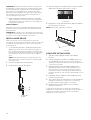
INSTALLATION REQUIREMENTS
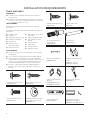
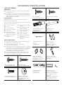
TOOLS AND PARTS
IMPORTANT:
Installer: Leave Installation Instructions with the
homeowner.
Homeowner: Keep Installation Instructions for future
reference. Save these Installation Instructions for the
local electrical inspector’s use.
TOOLS NEEDED:
Gather the required tools and parts before starting
installation.
Read and follow the instructions provided with any tools
listed here.
Cordless drill
Drill bits
Adjustable wrenches (2)
Phillips screwdriver
Small level
3/32" hex key
(panel kits only)
11/32" nut driver
3/8" and 1/2" open-end
wrenches
5/32" and 3/16" hex key
1/4" and 5/16" socket
drivers
Tape measure
Utility knife
Tape (painters)
Appliance dolly
PARTS NEEDED:
#8 x 3" (7.6 cm) wood screws (longer screws may be
needed) (6)
2" x 4" x 32" (5 cm x 10 cm x 81 cm) wood boards (2)
Custom wood overlay panels—consult a qualified
cabinetmaker or carpenter to make the custom wood
panels. See “Custom Wood Panel Dimensions and
Installation Requirements” for more information.
Flexible, codes-approved water supply tubing, a
ferrule, a union and a 1/4" (6.35 mm) compression
fitting.
Slotted Hex-head Screw
W10141645 (21)
Hex-head Pointed Screw
W10141189 (8)
Hex-head Blunt Screw
W10142233 (4)
Shoulder Washer (use with
hex-head pointed screw)
W10471946 (4)
Phillips-head Flat Screw
8281252 (28)
Round-head Screw
1163283 (24)
Door Adjustment Pin
(preinstalled)
W10234194 (2)
Door Stop Pin
W10234202 (2)
Drawer Panel Bracket
W10606815 (2)
Standard Integrated Grille
Bracket
W10182743—Left (1)
W10182741—Right (1)
Fully Integrated Grille
Bracket
W10260890—Left (1)
W10260891—Right (1)
Filler Board “L” Bracket
W10234199 (2)
Panel Top Bracket
W10667450 (2)
Top Grille Lower Trim
W10634858—36" BM (1)
W10606812—42" BM, SxS (1)

7
RC Hinge Cover Trim
W10648975—36" BM
(Right)
W10564251—36" FDBM
(Right)
W10606804—42" FDBM
(Right)
FC Hinge Cover Trim
W10611107—36" BM (Left)
W10582015—36" FDBM
(Left)
W10606808—42" FDBM
(Left)
Panel Templates
W10222281—SxS
W10488115—36" BM
W10704869—36" FDBM
W10488118—42" FDBM
W10489178—Grille
Handle Side Door Trim
W10611106—BM (Left)
W10648977—BM (Right
W10606802—FDBM (Right
W10606806—FDBM (Left)
Installation Block
W10234156
Grille—Bottom / Skirt—
Grille
W10189198 / W10188549—
42" BM
W10189196 / W10188547—
36" BM
W10005050 (2) - Screws
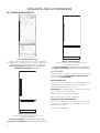
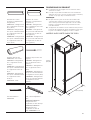
PRODUCT DIMENSIONS
Width dimensions were measured from hinge to
hinge.
When leveling legs are fully extended to 1⁄"
(3.2 cm) below rollers, add 1⁄" (3.2 cm) to the height
dimensions.
NOTE:
Do not remove the foam gasket from the top of the
compressor cover unless removal is necessary to fit
the unit under a soffit. Removal of the gasket will
cause loss in cooling efficiency.
If installing under a solid soffit, after installation raise
the leveling legs so that the gasket is pressed snugly
against the soffit.
36" SINGLE DOOR MODEL
24" (61 cm)
36" (91.4 cm)
83⁄"
(211.1 cm)

8
FRENCH DOOR BOTTOM MOUNT MODELS
MODEL WIDTH A HINGE EDGE TO HINGE EDGE
36 35⁄" (90.8 cm)
42 41⁄" (106 cm)
DOOR SWING DIMENSIONS
The location must permit both doors to open to a
minimum of 90°. Allow 4⁄" (11.4 cm) minimum space
between the side of the refrigerator and a corner wall.
NOTE : More clearance may be required if you are using
wood overlay panels, custom handles, or extended
handles.
36" SINGLE DOOR MODEL
36" (91.4 CM) AND 42" (106.6 CM)
FRENCH DOOR MODELS
MODEL A B
36 41" (104 cm) 39⁄" (101 cm)
42 44" (111.8 cm) 42⁄" (108.6 cm)
90º
110º
110˚
90˚
110˚
90˚
A B B A
24" (61 cm)
Width (A)
83⁄"
(211.1 cm)
56⁄"
(143.8 cm)
58⁄"
(149.2 cm)

9
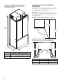
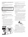
SITE PREPARATION
OPEN TO CEILING OR SOFFIT CABINET
MODEL WIDTH A
36 36" (91.4 cm)
42 42" (106.7 cm)
These type of installations require a minimum of
6" (15.24 cm) of open space above the refrigerator.
This space must not be blocked in any way, including
soffits.
Depth of cabinet must be less than 25" (63.5 cm).
If your opening does not meet these requirements,
you will need to make modifications.
CLOSED SOFFIT CABINET
MODEL WIDTH A
36 36" (91.4 cm)
42 42" (106.7 cm)
Depth of cabinet must be less than 25" (63.5 cm).
Height of soffit must not exceed 84" (213.3 cm).
Following illustrations explain the cabinet
construction (soffit and rear wall positions) required
for optimum ventilation and airflow.
If your opening does not meet these requirements,
you will need to make modifications.
84"
(213.3 cm)
25" (max.)
6" air gap min.
Cabinet
Cabinet
Ceiling or soffit
No obstruction
above refrigerator
Width (A)
Width (A)
84"
(213.3 cm)
25"
(max.)
Top View
Front View
✔
✔
X
X
Cabinet depth 25" and soffit
located at 84", provides proper
airflow/ventilation to the
refrigerator. Efficient cooling is
achieved.
Cabinet depth more than 25" and/
or soffit located at more than 84",
causes air gap at back and/or top
of the refrigerator. Air gap allows
warm air recirculation causing loss
in cooling efficiency.
Grey arrow = ambient air; Black arrow = warm air

10
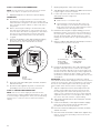
ANTI-TIP BOARDS
For open to ceiling or soffit cabinet constructions the
refrigerator must be braced with the help of primary and
secondary anti-tip boards.
PRIMARY ANTITIP BOARDS
IMPORTANT:
It is recommended that primary anti-tip boards be
installed before the refrigerator is installed.
Boards must be long enough to fully cover the width
of the compressor cover.
Place the boards so that the bottom surfaces of the
boards are 84" (213 cm) from the floor.
During installation, raise the refrigerator up until
the top of the refrigerator is making contact with
the bottom of the anti-tip boards. Do not crush the
compressor cover when raising the rear leveling legs.
NOTE: The foam gasket, on top of the compressor cover,
will compress to fit under the anti-tip board(s). There is no
need to trim the gasket.
To install primary anti-tip boards-
1. Mark the stud locations on rear wall.
2. Securely attach two 2" x 4" x 32" (5 cm x 10 cm x 81 cm)
boards to wall studs behind refrigerator. Use six
#8 x 3" (7.6 cm) (or longer) wood screws. The wood
screws must be screwed into the studs at least
1½" (3.8 cm). The boards must overlap the compressor
cover.
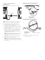
SECONDARY ANTITIP BOARDS
For all full height door or armoire panel installations,
the secondary anti-tip board is required to be
installed prior to door panel installation.
This anti-tip board is to be secured on the right side of
the cabinet enclosure as per the dimensions shown
in illustration.
Secure the secondary anti-tip board so that the
bottom surface of the secondary anti-tip board is
75⁄" (191.77 cm) from the floor (right hand side).
To install secondary anti-tip board-
1. Mark the stud locations on right hand side cabinet
wall.
2. Securely attach one 2" x 4" x 12" (5 cm x 10 cm x
30.4 cm) board to the cabinet on right hand side
cabinet using wood screws. Use three
#8 x 2" (5.08 cm) (or longer) wood screws.
NOTE:
It is recommended to drive the wood screws from
cabinet wall into the secondary anti-tip board as
shown in the illustration.
The board must have overlap of 1" (2.54) with the
refrigerator top.
Leave 4" (10.16 cm) free space at rear as shown in the
illustration.
A
B
CD
A. Two 2" x 4" x 32" (5 cm x 10 cm x 81 cm) boards
B. Attach to studs with six #8 x 3" (7.6 cm) screws.
C. Compressor cover
D. Distance from bottom of anti-tip boards to floor
2" (5 cm)
84"
(213.4 cm)
WARNING
Tip Over Hazard
Refrigerator is top heavy and tips easily
when not completely installed.
Install secondary anti-tip board to ensure
product stability.
Use two or more people to move and install
refrigerator.
Failure to do so can result in death or
serious injury.
A. Refrigerator C. Kitchen cabinet
B. Secondary anti-tip board D. Wood screws
75⁄"
(191.77 cm)
A
B
D
C
4" (10.16 cm)

11
LOCATION REQUIREMENTS
IMPORTANT: This refrigerator is designed for indoor,
household use only.
This appliance is intended to be used in household and
similar applications such as:
Staff kitchen areas in shops, offices and other working
environments.
Farm houses and by clients in hotels, motels and
other residential type environments.
Bed and breakfast type environments.
Catering and similar non-retail applications.
NOTE: The refrigerator is intended for use in a location
where the temperature ranges from a minimum of 55°F
(13°C) to a maximum of 43°C (110°F). The preferred room
temperature range for optimum performance, which
reduces electricity usage and provides superior cooling, is
between 15°C (60°F) and 32°C (90°F). It is recommended
that you do not install the refrigerator near a heat source,
such as an oven or radiator.
IMPORTANT:
Observe all governing codes and ordinances.
It is recommended that you do not install the
refrigerator near an oven, radiator, or other heat
source.
Do not install in a location where the temperature will
fall below 13°C (55°F).
Floor must support the refrigerator weight, more
than 600 lbs (272 kg), door panels and contents of
the refrigerator. Flooring under refrigerator must be
at same level as the room. Face of cabinetry must be
plumb.
Location should permit door to open fully. See “Door
Swing Dimensions.”
Location must permit top grille removal. See “Site
Preparation.”
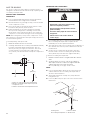
WATER SUPPLY REQUIREMENTS
IMPORTANT :
All installations must meet local plumbing code
requirements.
Connect to potable water supply only.
There is not enough clearance to achieve a flush
installation if a water shutoff valve is located in the
wall behind the refrigerator.
The water shutoff should be located in the base
cabinet on either side of the refrigerator or some
other easily accessible area. The water supply line,
however, must come up through the floor in the gray
shaded area shown.
A 1/2" (12.7 mm) hole for plumbing should be drilled
on the floor at least 6⁄" (16.5 cm) from the left-hand
side cabinet and should be no more than
2" (5 cm) away from the back wall. Refer above
illustration for more details.
The water supply connection is made at the front of
the refrigerator.
If additional tubing is needed, use copper tubing and
check for leaks. Install the copper tubing only in areas
where the household temperatures will remain above
freezing.
Do not use a piercing-type or 3/16" (4.76 mm) saddle
valve which reduces water flow and also clogs more
easily.
NOTE : Your refrigerator dealer has a kit available with
a 1/4" (6.35 mm) saddle-type shutoff valve, a union,
and copper tubing. Before purchasing, make sure a
saddle-type valve complies with your local plumbing
codes.
WARNING
Explosion Hazard
Keep flammable materials and vapors, such as
gasoline, away from refrigerator.
Failure to do so can result in death, explosion, or fire.
Do not use with water that is microbiologically unsafe or
of unknown quality without adequate disinfection before
or after the system. Systems certified for cyst reduction
may be used on disinfected waters that may contain
filterable cysts.
8" (20.3 cm)
6⁄" (16.5 cm)
2" (5 cm)

12
WATER PRESSURE
A cold water supply with water pressure between
30 psi and 120 psi (207 kPa and 827 kPa) is required to
operate the water dispenser and ice maker. If you have
questions about your water pressure, call a licensed,
qualified plumber.
REVERSE OSMOSIS WATER SUPPLY
IMPORTANT : The pressure of the water supply coming
out of a reverse osmosis system going to the water inlet
valve of the refrigerator needs to be between
30 psi and 120 psi (207 kPa and 827 kPa).
If a reverse osmosis water filtration system is connected
to your cold water supply, the water pressure to the
reverse osmosis system needs to be a minimum of
40 psi to 60 psi (276 kPa to 414 kPa).
If the water pressure to the reverse osmosis system is less
than 40 psi to 60 psi (276 kPa to 414 kPa):
Check to see whether the sediment filter in the
reverse osmosis system is blocked. Replace the filter if
necessary.
Allow the storage tank on the reverse osmosis system
to refill after heavy usage.
If your refrigerator has a water filter, it may further
reduce the water pressure when used in conjunction
with a reverse osmosis system. Remove the water
filter cartridge.
If you have questions about your water pressure, call a
licensed, qualified plumber.
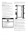
ELECTRICAL REQUIREMENTS
Before you move your refrigerator into its final location, it
is important to make sure you have the proper electrical
connection.
A grounded 3 prong electrical outlet should be located
within a specified number of inches from the right-hand
side cabinets or end panel. See the chart following the
illustration for the number of inches required for your
model.
If the supply cord is damaged, it must be replaced
by the manufacturer or its service agent or a similar
qualified person. Do not use a cord that shows cracks or
abrasion damage along its length or at either the plug or
connection end.
RECOMMENDED GROUNDING METHOD
A 115 V, 60 Hz, AC only, 15 A or 20 A fused, grounded
electrical supply is required. It is recommended that a
separate circuit serving only your refrigerator be provided.
Use an outlet that cannot be turned off by a switch. Do
not use an extension cord.
IMPORTANT : If this product is connected to a GFCI
(Ground Fault Circuit Interrupter) protected outlet,
nuisance tripping of the power supply may occur,
resulting in loss of cooling. Food quality and flavor may
be affected. If nuisance tripping has occurred, and if the
condition of the food appears poor, dispose of it.
NOTE : Before performing any type of installation or
cleaning, remove the top grille and turn the master power
switch to OFF or disconnect power at the circuit breaker
box.
When you are finished, turn ON the master power switch
or reconnect power at the circuit breaker box. Then reset
the control to the desired setting.
Electrical Shock Hazard
Plug into a grounded 3 prong outlet.
Do not remove ground prong.
Do not use an adapter.
Do not use an extension cord.
Failure to follow these instructions can result in death,
fire, or electrical shock.
WARNING
4"
(10.2 cm)
77"
(196 cm)

13
STAINLESS STEEL PANEL KIT
INSTALLATION REQUIREMENTS
Refer instructions received with full height door panel kit.
CUSTOM WOOD PANEL DIMENSIONS
AND INSTALLATION REQUIREMENTS
Refer instructions received with Armoire kit.
INSTALLATION INSTRUCTIONS
UNPACK THE REFRIGERATOR
IMPORTANT :
Do not remove the film covering until the refrigerator
is in its operating location.
All four leveling legs must contact the floor to support
and stabilize the full weight of the refrigerator.
Keep the cardboard shipping piece or plywood under
the refrigerator until it is installed in the operating
location.
1. Remove and save the literature package and
hardware kit located inside the refrigerator. Remove
and save the literature, grille, and trim taped to the
outside of the refrigerator.
NOTE : Do not remove tape and door bracing until
the refrigerator is in its final location.
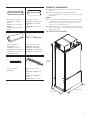
MOVE THE REFRIGERATOR INTO HOUSE
1. Place an appliance dolly under the left side of the
refrigerator as shown. Place the corner posts from
the packing materials over the trims as appropriate.
Slowly tighten the strap.
2. Place pieces of the shipping carton on the floor when
rolling the dolly and refrigerator into the house. Move
the refrigerator close to the built-in opening.
3. Place top of cardboard carton or plywood under
refrigerator. Stand the refrigerator up. First, place the
left bottom edge of the refrigerator on the floor, stand
the refrigerator upright and then lower the right-
hand side of the refrigerator to the floor.
4. Reassemble the trim and top grille after the dolly has
been removed from the refrigerator.
CONNECT THE WATER SUPPLY
Read all directions before you begin.
IMPORTANT :
If you turn the refrigerator on before the water line is
connected, turn the ice maker OFF.
Connect to potable water supply only.
CONNECT TO WATER LINE
PARTS NEEDED
Minimum 7 ft (2.13 m) flexible, codes-approved water
supply line.
WARNING
Tip Over Hazard
Refrigerator is top heavy and tips easily when not
completely installed.
Keep doors taped closed until refrigerator is
completely installed.
Use two or more people to move and install
refrigerator.
Failure to do so can result in death or serious injury.
WARNING
Tip Over Hazard
Refrigerator is top heavy and tips easily when not
completely installed.
Keep doors taped closed until refrigerator is
completely installed.
Use two or more people to move and install
refrigerator.
Failure to do so can result in death or serious injury.
Do not use with water that is microbiologically unsafe or
of unknown quality without adequate disinfection before
or after the system. Systems certified for cyst reduction
may be used on disinfected waters that may contain
filterable cysts.

14
STYLE 1SHUTOFF VALVE CONNECTION
NOTE : If your water line connection does not look like
Style 1, see “Style 2—Copper Line Connection.”
1. Unplug refrigerator or disconnect power supply.
IMPORTANT :
There is not enough clearance to achieve a flush
installation if a water shutoff valve is located in the
wall behind the refrigerator. The water shutoff should
be located in the base cabinet on either side of the
refrigerator.
Before attaching the tubing to shutoff valve, flush
the main water supply line to remove particles and
air in the water line. Allow enough flow so that water
becomes clear. Flushing the water line may help
avoid filters and/or water valves from becoming
clogged.
2. Connect the flexible, codes-approved water supply
line to the water shutoff valve by threading the
provided nut onto the shutoff valve as shown.
3. Place the end of the tubing into a bucket, and turn
shutoff valve ON.
4. Check for leaks. Tighten any nuts or connections
(including connections at the valve) that leak.
STYLE 2COPPER LINE CONNECTION
NOTE : If there is a water supply line that meets the
specifications in “Water Supply Requirements,” proceed
to “Connecting to Refrigerator.” If not, use the following
instructions to connect to the household cold water
supply.
1. Unplug refrigerator or disconnect power.
2. Turn OFF main water supply. Turn ON nearest faucet
long enough to clear line of water.
3. Locate a 1/2" to 1⁄" (1.3 cm to 3.18 cm) vertical cold
water pipe near the refrigerator.
IMPORTANT :
Make sure it is a cold water pipe.
Horizontal pipe will work, but drill on the top
side of the pipe, not the bottom. This will help
keep water away from the drill and keep normal
sediment from collecting in the valve.
4. Determine the length of copper tubing you need.
Measure from the connection on the refrigerator to
the water pipe. Add 7 ft (2.1 m) to allow for cleaning.
Use 1/4" (6.35 mm) O.D. (outside diameter) copper
tubing. Be sure both ends of copper tubing are cut
square.
5. Using a cordless drill, drill a 1/4" (6.35 mm) hole in the
cold water pipe you have selected.
6. Fasten the shutoff valve to the cold water pipe with
the pipe clamp. Be sure the outlet end is solidly in
the 1/4" (6.35 mm) drilled hole in the water pipe and
that the washer is under the pipe clamp. Tighten the
packing nut. Tighten the pipe clamp screws slowly
and evenly so washer makes a watertight seal. Do not
overtighten.
IMPORTANT : Before attaching the tubing to shutoff
valve, flush the main water supply line to remove particles
and air in the water line. Allow enough flow so that water
becomes clear. Flushing the water line may help avoid
filters and/or water valves from becoming clogged.
7. Slip the compression sleeve and compression nut
on the copper tubing as shown. Insert the end of
the tubing into the outlet end squarely as far as it
will go. Screw compression nut onto outlet end with
adjustable wrench. Do not overtighten the clamp or
the sleeve. This will crush the copper tubing.
8. Turn off the shutoff valve on the water pipe. Coil the
copper tubing.
9. Connect the flexible, codes-approved water supply
line to the water shutoff valve by threading the
provided nut onto the shutoff valve.
10. Place the end of the tubing into a bucket, and turn
shutoff valve ON.
11. Check for leaks around the saddle valve. Tighten any
nuts or connections (including connections at the
valve) that leak.
A
B
C
A. Bulb
B. Nut
C. Water tubing
A
B
C
D
EF
G
A. Cold water pipe
B. Pipe clamp
C. Copper tubing
D. Compression nut
E. Compression sleeve
F. Shutoff valve
G. Packing nut

15
CONNECT TO REFRIGERATOR
PARTS SUPPLIED
1/4" to 1/4" (6.35 mm to 6.35 mm) male-to-male
coupling.
NOTE : The flexible, codes-approved water supply line
should connect to the supply valve through the floor.
1. Unplug the refrigerator or disconnect power.
2. Connect the 7 ft (2.13 m) flexible codes-approved
water tube to the water supply valve.
3. Flush the main water supply line to remove particles
and air in the water line. Allow enough flow so that
water becomes clear.
4. Tape the 7 ft (2.13 m) flexible codes-approved water
supply line to the floor, 7" (17.78 cm) from the left
side of the refrigerator. Tape along the length of
the tubing, which will allow it to pass beneath the
refrigerator without interference.
NOTE : Allow a minimum of 26" (66.04 cm) of flexible
codes approved water supply line to be loose at
the front of the refrigerator for connecting to the
refrigerator.
5. Connect the 7 ft (2.13 m) flexible codes-approved
water supply line to the refrigerator.
NOTE : If the main water shutoff valve is behind the
refrigerator, a secondary water shutoff valve may be
installed in line with the water supply line at the front
of the product.
OVERMOLD COUPLING ON SOME MODELS
DISCRETE COUPLING ON SOME MODELS
6. Turn on the water supply valve and check all
connections for leaks.
BA C
A. Household water line
B. Nut (purchased)
C. Ferrule (purchased)
A
B
CD
EFG
A. Household water line
B. Nut (purchased)
C. Ferrule (purchased)
D. Coupling
E. Bulb
F. Nut
G. Refrigerator water tubing
7"
(17.78 cm)
2⁄" (6.35 cm) max.

16
PLUG IN REFRIGERATOR
If the supply cord is damaged, it must be replaced
by the manufacturer or its service agent or a similar
qualified person. Do not use a cord that shows cracks or
abrasion damage along its length or at either the plug or
connection end.
1. Set control switch at top of cabinet to the OFF
position.
2. Plug into a grounded 3 prong outlet.
INSTALL SIDE TRIMS
The side trims cover the space between the refrigerator
and the adjacent cabinets. There is a trim piece taped to
each side of the refrigerator. Install each trim piece to the
side of the refrigerator to which it is taped.
1. Remove the tape attaching the trim pieces to the
sides of the refrigerator. Set the trim pieces aside.
2. Remove the four screws from the side of the
refrigerator cabinet.
3. Using the original holes and the screws removed in
Step 2, fasten the side trim to the refrigerator cabinet.
NOTE : Make sure to fasten each trim piece to the
side of the refrigerator cabinet from which it was
removed. The tapered shaped edge should be
forward with the notches aligning with the door
hinges.
TOP VIEW
MOVE REFRIGERATOR TO FINAL
LOCATION
IMPORTANT :
A flush installation is NOT possible with a
24" (60.9 cm) deep opening.
To avoid floor damage, make sure levelers are raised
(not touching floor) and refrigerator is on rollers
before moving.
Use the installation block, attached to the door hinge,
as a reference to make sure the refrigerator is pushed
back far enough into the opening, so that when
the panels are installed they will be flush with the
adjacent cabinets.
Electrical Shock Hazard
Plug into a grounded 3 prong outlet.
Do not remove ground prong.
Do not use an adapter.
Do not use an extension cord.
Failure to follow these instructions can result in death,
fire, or electrical shock.
WARNING
A
A. Side trim screws
A
B
C
A. Side trim
B. Adjacent cabinet
C. Door
WARNING
Tip Over Hazard
Refrigerator is top heavy and tips easily when not
completely installed.
Keep doors taped closed until refrigerator is
completely installed.
Use two or more people to move and install
refrigerator.
Failure to do so can result in death or serious injury.

17
After the refrigerator is leveled and aligned, remove
the installation block from the door hinge and use
it to check the spacing between the panels and
adjacent cabinets.
NOTE : The installation block is designed to provide
accurate spacing for 3/4" (1.9 cm), 3/8" (9.53 mm) and
1/8" (3.18 mm).
1. Place top of cardboard carton or plywood under
refrigerator. Remove dolly.
2. Move the refrigerator straight back and evenly into
the opening. Be sure that the water tubing is not
kinked and the power supply cord is on top of the
refrigerator.
NOTE : If the power supply cord is behind the
refrigerator, it will not install properly.
3. Make sure the installation block is flush with the
adjacent cabinets.
NOTE : To achieve a flush installation, it is critical to
verify a 3/4" (1.9 cm) depth from the front face of the
adjacent cabinetry to the refrigerator.
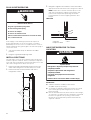
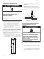
LEVEL AND ALIGN REFRIGERATOR
IMPORTANT : All four leveling legs must contact the floor
to support and stabilize the full weight of refrigerator.
Rollers are for moving the refrigerator, not for permanent
support.
After moving the refrigerator to its final location:
1. Use a 5/16" socket driver to turn the leveling bolts
clockwise to extend the legs to the floor as shown.
The rollers should be off the floor.
2. Adjust the leveling legs to level and align the
refrigerator from left to right and front to back so that
the refrigerator is level and aligned with the cabinets.
3. Continue adjusting the leveling legs until the top of
the refrigerator is making contact with the bottom of
the solid soffit, or the bottom of the anti-tip boards, if
anti-tip boards were used. Do not crush the
compressor cover.
3/4"
(1.9 cm)
3/8"
(9.53 mm)
1/8"
(3.18 mm)
A
B
C
A. Adjacent cabinet or wall
B. Installation block
C. Face of refrigerator
WARNING
Tip Over Hazard
Refrigerator is top heavy and tips easily when not
completely installed.
Keep doors taped closed until refrigerator is
completely installed.
Use two or more people to move and install
refrigerator.
Failure to do so can result in death or serious injury.
A B A
B
A. Rear leveling bolt
B. Front leveling bolt
2" (5 cm)
84"
(213.4 cm)
A
B
CD
A. Two 2" x 4" x 32" (5 cm x 10 cm x 81 cm) boards
B. Attach to studs with six #8 x 3" (7.6 cm) screws
C. Compressor cover
D. Distance from bottom of anti-tip board to floor
3/4" (1.9 cm)

18
IMPORTANT : Adjust in small increments to keep from
damaging the cabinet trim and causing problems with
the door alignment or top grille fit. To avoid damage to
the cabinet or leveling legs, do not apply more than
50 inch-pounds (5.65 Nm) of torque to the leveling bolts.
The leveling legs can be extended to a maximum of
1⁄" (3.18 cm) below the rollers.
1. After leveling the refrigerator, again use a straight
edge or 4-ft level across the front of the refrigerator
installation blocks to the cabinets to check that the
refrigerator is still flush.
INSTALL PANELS
Refer instructions received with full height door panel
kit /Armoire kit to install stainless steel / Custom Wood
Overlay Panels.
IMPORTANT : JennAir is not responsible for the removal
or addition of molding or wood overlay panels that would
not allow access to the refrigerator for service.
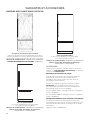
INSTALL BASE GRILLE
There are two pieces to the base grille to allow for a
custom fit: the base grille itself and the skirt. The skirt can
be added to the base grille in order to extend it all the
way to the floor.
1. To see whether the skirt is needed, place the base
grille into position. Do not attach the base grille to
the refrigerator. Measure the distance between the
bottom of the base grille and the floor. The gap must
be a minimum of 1/2" (1.27 cm) in order to add the
skirt.
NOTE : If the gap measures less than 1/2" (1.27 cm),
skip steps 3 and 4 of the instructions, and install the
base grille only.
2. Remove the film from the base grille.
3. Snap the skirt onto the base grille.
4. Trim the skirt by scoring the proper “V” groove with a
utility knife. Break the skirt at the score line.
5. Using the 2 screws, attach the base grille assembly to
the refrigerator as shown.
NOTE : Drive in the right side screw first.
COMPLETE INSTALLATION
1. Turn the water supply line valve to the “Open”
position.
2. Turn the refrigerator switch to the ON position. See
“Power On/ Off Switch” in the Use & Care Guide for
instructions. Wait a few minutes. Check the water line
connections for leaks.
3. Remove all boxes, parts packages and packing
materials from the interior of the refrigerator. See
the “Cleaning” section in the Use & Care Guide for
instructions. Remove the film and cardboard from
the grille and doors or door frame, depending on your
model.
4. Install the shelves and bins in the refrigerator and
freezer compartments.
5. The controls are preset at the factory to the midpoint
setting. Check that the compressor is operating
properly and that all the lights are working.
6. Flush the water system before use. See “Water
System Preparation.”
To get the most efficient use from your new built-in
refrigerator, read the Use & Care Guide. Keep Installation
Instructions and Use & Care Guide near the built-in
refrigerator for easy reference.
A
B
A. Base grille
B. Skirt
A
A. “V” groove
A
A. Screws

19
INTRODUCTION
SÉCURITÉ DU RÉFRIGÉRATEUR
Risque possible de décès ou de blessure grave si vous ne
suivez pas immédiatement les instructions.
Risque possible de décès ou de blessure grave si vous
ne suivez pas les instructions.
Tous les messages de sécurité vous diront quel est le danger potentiel et vous disent comment réduire le risque de blessure et
ce qui peut se produire en cas de non-respect des instructions.
Votre sécurité et celle des autres est très importante.
Nous donnons de nombreux messages de sécurité importants dans ce manuel et sur votre appareil ménager. Assurez-vous de
toujours lire tous les messages de sécurité et de vous y conformer.
AVERTISSEMENT
DANGER
Voici le symbole d’alerte de sécurité.
Ce symbole d’alerte de sécurité vous signale les dangers potentiels de décès et de blessures graves à vous
et à d’autres.
Tous les messages de sécurité suivront le symbole d’alerte de sécurité et le mot “DANGER” ou
“AVERTISSEMENT”. Ces mots signifient :
AVERTISSEMENT
Risque de basculement
Le réfrigérateur est lourd au sommet et bascule
facilement lorsqu'il n'est pas complètement installé.
Garder les portes fermées avec un ruban adhésif
jusqu'à l'installation complète du réfrigérateur.
Utiliser deux ou plus de personnes pour déplacer et
installer le réfrigérateur.
Le non-respect de ces instructions peut causer un
décès ou une blessure grave.

20
VARIANTES ET ACCESSOIRES
MODÈLES AVEC PORTE SIMPLE DE 36PO
Conception de panneaux personnalisés
Comporte des panneaux et du matériel personnalisés
fournis par l’ébéniste pour une apparence harmonieuse
conçue pour s’intégrer aux armoires de cuisine existantes.
Numéros de modèles de base: JB36NXFXLE et JB36NXFXRE
NUMÉRO D’ENSEMBLE POUR ARMOIRE: W10663562
Acier inoxydable NOIR™
Portes avec habillage en acier inoxydable
etnouvellespoignées NOIR™.
Numéros de modèles de base: JB36NXFXLE et JB36NXFXRE
Numéro de modèle d’ensemble de panneaux:
JBBFR36NHM et JBBFL36NHM
Acier inoxydable RISE™
Portes avec habillage en acier inoxydable
etnouvellespoignées RISE™.
Numéros de modèles de base: JB36NXFXLE et JB36NXFXRE
Numéro de modèle d’ensemble de panneaux:
JBBFR36NHL et JBBFL36NHL
ACCESSOIRES
Toutes les pièces d’usine sont disponibles en appelant
JennAir® au 1800JENNAIR (1800536-6247). Au Canada,
composer le 1800536-6247.
ENSEMBLES DE POIGNÉES DE PORTE
Pour des panneaux de bois décoratifs personnalisés
uniquement, il est possible de commander des
ensembles de poignées. Suivre les instructions de
l’ensemble pour l’installation.
Chaque ensemble de poignées contient 2 poignées.
IMPORTANT: Ces ensembles de poignées ne sont
pas conçus pour être utilisés avec des ensembles de
panneaux de porte en acier inoxydable.
Acier inoxydable RISE™ – Réfrigérateur avec congélateur
en bas – W11231245
Acier inoxydable NOIR™ – Réfrigérateur avec congélateur
en bas – W11194767
ENSEMBLE DE PANNEAUX POUR PORTE DE STYLE ARMOIRE
Consulter les instructions d’installation incluses avec
l’ensemble pour armoire pour obtenir les dimensions des
panneaux de bois décoratifs personnalisés et les détails
d’installation.
Modèle de 36po – W10663562
La page est en cours de chargement...
La page est en cours de chargement...
La page est en cours de chargement...
La page est en cours de chargement...
La page est en cours de chargement...
La page est en cours de chargement...
La page est en cours de chargement...
La page est en cours de chargement...
La page est en cours de chargement...
La page est en cours de chargement...
La page est en cours de chargement...
La page est en cours de chargement...
La page est en cours de chargement...
La page est en cours de chargement...
La page est en cours de chargement...
La page est en cours de chargement...
La page est en cours de chargement...
La page est en cours de chargement...
La page est en cours de chargement...
La page est en cours de chargement...
-
 1
1
-
 2
2
-
 3
3
-
 4
4
-
 5
5
-
 6
6
-
 7
7
-
 8
8
-
 9
9
-
 10
10
-
 11
11
-
 12
12
-
 13
13
-
 14
14
-
 15
15
-
 16
16
-
 17
17
-
 18
18
-
 19
19
-
 20
20
-
 21
21
-
 22
22
-
 23
23
-
 24
24
-
 25
25
-
 26
26
-
 27
27
-
 28
28
-
 29
29
-
 30
30
-
 31
31
-
 32
32
-
 33
33
-
 34
34
-
 35
35
-
 36
36
-
 37
37
-
 38
38
-
 39
39
-
 40
40


Jenn-Air JB36NXFXRE Manuel utilisateur
- Catégorie
- Frigos
- Taper
- Manuel utilisateur
- Ce manuel convient également à
dans d''autres langues
- English: Jenn-Air JB36NXFXRE User manual