
1
UCS 601 • User Guide
IMPORTANT NOTE:
Go to www.extron.com for the complete UCS 601 specications before connecting the product to the power
source.
The UCS 601 is a pro AV dock that connects a USB‑C equipped laptop to an HDMI display and USB devices for use in Unied
Communications spaces. This dock supports HDMI 2.0, DisplayPort 1.2, USB 3.2 (SuperSpeed 10 Gbps) and HDCP 2.3
specications, with resolutions up to 4K @ 60 Hz, and a built‑in USB hub for USB peripherals such as cameras, touch displays,
and microphones.
The rack mountable UCS 601 has a 1 inch high, quarter rack wide, 6 inch deep metal enclosure, allowing the UCS 601 to take
advantage of a variety of mounting options (see Mounting on page 4).
FCC Class A Notice
This equipment has been tested and found to comply with the limits for a Class A digital device, pursuant to part 15 of the
FCC rules. The Class A limits provide reasonable protection against harmful interference when the equipment is operated in a
commercial environment. This equipment generates, uses, and can radiate radio frequency energy and, if not installed and used in
accordance with the instruction manual, may cause harmful interference to radio communications. Operation of this equipment in a
residential area is likely to cause interference. This interference must be corrected at the expense of the user.
Features
• Provides interface between USB‑C® equipped sources that support DisplayPort Alt Mode and HDMI displays and
peripherals.
• Power Delivery — Provides up to 60 watts of charging power to the USB‑C source.
• Supports computer and video resolutions up to 4K/60 @ 4:4:4 with data rates up to 18 Gbps.
• HDCP compliant — HDCP 2.3 and HDCP 1.4 pass through.
• Extron Everlast™ Power Supply — Comes equipped with an energy ecient 100‑240 VAC, 50 to 60 Hz, internal universal
power supply.
• Passes EDID information from HDMI display to the source.
• LED indicators for power, power delivery, and signal presence — Provides visual indication of system status for real‑time
feedback and monitoring of key performance parameters.
• 1/4 rack wide, 1 inch high, and 6 inch deep rack‑mountable enclosure.
• Includes ZipClip 200® mounting accessory.
• Includes LockIt® HDMI cable lacing brackets.

2
UCS 601 • User Guide (Continued)
Application Diagram
50/60 Hz
1.4A MAX
100-240VAC
MODEL 80
50/60 Hz
1.4A MAX
100-240VAC
OUTPUT
OUTPUT
Display
USB
Camera
Laptop
USB
Camera
Sound Bar
Sound
Bar
Extron
USBC Pro Series
SuperSpeed 5Gbps
USB-C Optical Cable
Extron
USBC Pro Series
Extron
UCS 601
Extron
UCS 601
HDMI
USB
USB
Figure 1. UCS 601 Application Diagram
Front Panel Features Rear Panel Features
USB-C
ALT
MODE
4K30/SS 10G
4K60/USB 2.0
50-60 Hz
--A MAX
100-240V
HDMI
60W
OUTPUT
INPUT
UCS 601
e
VIDEO
SS 10G
123
500mA
900mA
INPUT
DEVICES
A
A
A
EEE
FFFGGG HHH
B
B
B D
D
D
C
C
C
USB-C
ALT
MODE
4K30/SS 10G
4K60/USB 2.0
50-60 Hz
--A MAX
100-240V
HDMI
60W
OUTPUT
INPUT
UCS 601
e
VIDEO
SS 10G
123
500mA
900mA
INPUT
DEVICES
AAAEEE
FFFGGG HHH
BBB DDD
CCC
Figure 2. UCS 601 Front Panel Figure 3. UCS 601 Rear Panel
A Power LED — Indicates power status of unit.
B USB 3.2 Type‑A Device Ports (3) — Connect up to three USB peripheral devices (such as cameras, touch displays, and
microphones).
C Power delivery LED — Indicates status of USB‑C power delivery (see figure 3, G) to the host PC.
D Video signal LED — Indicates input video signal status.
E IEC Power Connector — Connect the AC power cord to the AC power input.
F DisplayPort Alt Mode function Switch — Toggle up to support 4K, 30 Hz and USB 3.2. Toggle down to support 4K, 60 Hz
and USB 2.0.
1
2

3
ATTENTION:
• Unless otherwise stated, the AC/DC adapters are not suitable for use in air handling spaces or in wall cavities. The
power supply is to be located within the same vicinity as the Extron AV processing equipment in an ordinary location,
Pollution Degree 2, secured to the equipment rack within the dedicated closet, podium, or desk.
• Sauf mention contraire, les adaptateurs AC/DC ne sont pas appropriés pour une utilisation dans les espaces
d’aération ou dans les cavités murales. La source d’alimentation doit être située à proximité de l’équipement de
traitement audiovisuel dans un endroit ordinaire, avec un degré 2 de pollution, fixé à un équipement de rack à
l’intérieur d’un placard, d’une estrade, ou d’un bureau.
• The installation must always be in accordance with the applicable provisions of National Electrical Code ANSI/NFPA
70, article 725 and the Canadian Electrical Code part 1, section 16. The power supply shall not be permanently fixed
to building structure or similar structure.
• Cette installation doit toujours être en accord avec les mesures qui s’applique au National Electrical Code ANSI/
NFPA 70, article 725, et au Canadian Electrical Code, partie 1, section 16. La source d’alimentation ne devra pas
être fixée de façon permanente à une structure de bâtiment ou à une structure similaire.
NOTE: Before toggling the DisplayPort Alt Mode switch (F), disconnect the AC power cord (from E) and USB‑C cable
(from G) and power cycle. After 45 seconds, reconnect the power cable, followed by the USB‑C cable.
G USB‑C Input — Connect a USB‑C source device to the USB‑C input.
NOTE: The USB‑C port provides up to 60 W of power to a connected source device. If the source requires greater than
60 W of power, the source is still powered, or may charge slowly.
H HDMI Output — Connect an HDMI output device to the HDMI output.
NOTE: Extron recommends using HDMI Pro Series cables for 4K/UHD signals.
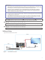
Cabling and Setup
Figure 4 shows connections for the UCS 601.
POWER
12V
0.3A MAX
INPUT
OUTPUT
+V OUTDIGITAL I / O
HDMI/CECHDMI
G24
IR /S
SG
21G 43G
Extron
HD CTL 100
HDMI Controller
Display
HDMI/CEC
MODEL 80
FLAT PANEL
Table
Display
Extron
USBC Pro Series
SuperSpeed 5 Gbps
USB-C Optical Cable
Extron
UCS 601
UCS 601
e
VIDEO
SS 10G
123
500mA
900mA
INPUT
DEVICES
USB-C
ALT
MODE
4K30/SS 10G
4K60/USB 2.0
50-60 Hz
--A MAX
100-240V
HDMI
60W
OUTPUT
INPUT
HDMI
USB
POWERSTANDBY
USB
Camera
Table
Display
Extron
UCS 601
UCS 601
e
VIDEO
SS 10G
123
500mA
900mA
INPUT
DEVICES
USB-C
ALT
MODE
4K30/SS 10G
4K60/USB 2.0
50-60 Hz
--A MAX
100-240V
HDMI
60W
OUTPUT
INPUT
HDMI
USB
POWERSTANDBY
USB
Camera
Display
MODEL 80
FLAT PANEL
Extron
USBC Pro Series
SuperSpeed 5 Gbps
USB-C Optical Cable
Figure 4. Front and Rear Connections
3

4
UCS 601 • User Guide (Continued)
LockIt Lacing Brackets
Use LockIt Lacing Brackets to securely fasten USB‑C and HDMI cables to the device as follows (see gure below):
1. Plug the cable into the port (1).
2. Loosen the connection mounting screw from the
panel, (2) enough to allow the LockIt lacing bracket
to be placed over it. The screw does not need to be
removed.
3. Place the LockIt lacing bracket on the screw and
against the connector (3).
4. Tighten the screw to secure the bracket (4).
ATTENTION:
• Do not overtighten the connector
mounting screw. The shield it fastens to
is very thin and can easily be stripped.
• Ne serrez pas trop la vis de montage du
connecteur. Le blindage auquel elle est
attachée est très fin et peut facilement
être dénudé.
5. Loosely tie the included tie wrap around the
connector and the LockIt lacing bracket.
6. While holding the connector securely against the
lacing bracket, use pliers or similar tool to tighten the
tie wrap (5).
7. Remove any excess length.
Mounting
UL Rack Mounting Guidelines
There are several optional accessories for mounting the UCS 601 (see the mounting options at www.extron.com).
CAUTION: Risk of minor personal injury:
• Elevated operating ambient temperature — If the equipment is installed in a closed or multi‑unit rack assembly, the
operating ambient temperature of the rack environment may be greater than room ambient. Therefore, consider installing
the equipment in an environment compatible with the maximum ambient temperature (Tma) specified by Extron.
• Reduced air flow — Install the equipment in the rack so that the amount of air flow required for safe operation of the
equipment is not compromised.
• Mechanical loading — Mount the equipment in the rack so that uneven mechanical loading does not create a hazardous
condition.
• Circuit overloading — When connecting the equipment to the supply circuit, consider the connection of the equipment to
the supply circuit and the effect that circuit overloading might have on overcurrent protection and supply wiring. Consider
equipment nameplate ratings when addressing this concern.
• Reliable earthing (grounding) — Maintain reliable grounding of rack‑mounted equipment. Pay particular attention to
supply connections other than direct connections to the branch circuit (such as the use of power strips).
1
2
3
4
5
4
3
1
2
5
3
4
USB type-C HDMI

5
Consignes UL pour le montage en rack
Les consignes UL (« Underwriters Laboratories ») suivantes concernent l’installation en rack d’un boîtier UCS 601 :
ATTENTION : Risque de blessure mineure :
• Température ambiante élevée — En cas d’installation de l’équipement dans un rack fermé ou composé de plusieurs
unités, la température du rack peut être supérieure à la température ambiante. Par conséquent, il est préférable
d’installer l’équipement dans un environnement qui respecte la température ambiante maximale (Tma) spécifiée par
Extron.
• Réduction du flux d’air — Si l’équipement est installé dans un rack, veillez à ce que le flux d’air nécessaire pour un
fonctionnement sécurisé de l’équipement soit respecté.
• Charge mécanique — Installez l’équipement en rack de manière à éviter toute situation dangereuse causée par le
déséquilibre de la charge mécanique.
• Surcharge électrique — Lorsque vous connectez l’équipement au circuit d’alimentation, observez la connexion de
l’équipement et étudiez les effets possibles d’une surcharge du circuit sur les protections contre les surintensités et les
conducteurs d’alimentation. Consultez à cet égard les indications de la plaque d’identification de l’équipement.
• Mise à la terre — Assurez‑vous que l’équipement est correctement mis à la terre. Accordez une attention particulière aux
connexions électriques autres que les connexions directes au circuit de dérivation (ex. : les multiprises).
ZipClip 200 Installation and Mounting
The UCS 601 can be mounted under a desk, onto a wall or other furniture using the ZipClip 200 (included). See ZipClip mounting
options at www.extron.com.
1. Mount the ZipClip 200 onto a rack rail or an under‑desk
mounting surface, using the four included mounting
screws (see the gure on the right).
2. Mount the UCS 601 to the ZipCaddy 200.
a. Align the mounting holes on the bottom of the UCS
unit with the mounting holes on the ZipCaddy (see
the figure below, left), and fasten the screws.
b. Detach the UCS 601 from the ZipClip 200 mounting
location, using the quick‑release tab (see the figure
below, right).
e
UCS 601
ZipCaddy 200
UCS 601
1
LR
RS-232 IR
Tx Rx Tx RxG
TxRx G
RESET
XTP
DTP
+48V
MIC/LINE
113
24
2
3
4
8
4
CLASS 2 WIRING
8 /
OVER TP
REMOTE
SIG LINK
IN
AUDIO OUTPUTS
AMP OUTPUT
INPUTS
RS-232 IR
Tx Rx Tx RxG
RS-232 IR
Tx Rx Tx RxG
XTP
DTP
XTP
DTP
9 10
OVER TP
SIG LINK
IN
SIG LINK
IN
RS-232 IR
Tx Rx Tx RxG
1
LR
3
LR
3
L R
5
L R
4
LR
2
L R
4
L R
6
L R
G LINK
OUT
6B 6
XTP
S/PDIF
OUT
DTP HDBT
XTP
DTP
HDBT
SIG LINK
OUT
SIG LINK
OUT
78
RS-232 IR
Tx Rx Tx Rx
XTP
DTP
HDBT
G
RS-232 IR
Tx Rx Tx RxG
OVER TP
S VIDEO CH 3
CH 4
VHF/UHF
VHF(SAT)/UHF
IN
OUT
TEL LINE
AC IN
AC OUT
RGB OUTPUT
A-V OUTPUT
AUDIO
B H/HV V
A
AUDIO
LRB
RB
ISOG
C SYNC
50/60 Hz
100-240V 1.3A
RGB OUTPUT
A-V OUTPUT
AUDIO
BH/HV V
A
AUDIO
LRB
RB
ISOG
C SYNC
50/60 Hz
100-240V 1.3A
S VIDEO CH 3
CH 4
VHF/UHF
VHF(SAT)/UHF
IN
OUT
TEL LINE
AC IN
AC OUT
ZipClip 200
ZipClip 200
E
E
E
E
E
E
E
E
E
E
E
E
e
UCS 601
ZipClip 200
UCS 601

6
68-3741-01 Rev. A
12 23
For information on safety guidelines, regulatory compliances, EMI/EMF compatibility, accessibility, and related topics, see the Extron
Safety and Regulatory Compliance Guide on the Extron website.
© 2023 Extron — All rights reserved. www.extron.com
All trademarks mentioned are the property of their respective owners.
Worldwide Headquarters: Extron USA West, 1025 E. Ball Road, Anaheim, CA 92805, 800.633.9876
System Operation
No drivers are required for a host PC to function with the UCS 601 unit. The unit is detected by the operating system, and
appropriate USB drivers are loaded. Certain USB peripherals, such as gaming keyboards, USB interactive white boards, scanners,
printers, and similar devices, require specic drivers installed on the PC. To obtain drivers, see the USB device installation
instructions or the peripheral device manufacturer website.
The system is fully operational when the unit, PC or USB host, and peripherals are connected and powered. If problems are
encountered, ensure that all cables are routed and connected properly, and that the latest drivers for each peripheral are installed.
Troubleshooting
USB signals are generally reliable, but are susceptible to bad connections or signal loss from cables that are too long. To avoid
loss of data and communication, follow these guidelines:
• The USB cables that connect the transmitter to the host, or the receiver to peripheral devices, should not exceed 6 feet
(1.8 meters).
• When connecting the host or peripherals, use only cables designed for USB signals.
• Avoid or limit the use of adapters.
The UCS 601 works as described in point‑to‑point applications. Do not use additional adapters, patch panels, or couplers with
USB cables or ber optic cables. Additional links in the signal chain can result in reduction of signal integrity and overall system
performance.
When properly connected and operating, the Power LED, Devices LEDs, Input Power LED and Video Signal LED are lit. Front
panel LEDs are also useful for troubleshooting. The following table outlines the status indicated by each LED:
LED
Indicator On Off
Power AC power supply is connected and operating
properly.
AC power supply is NOT connected or is defective.
Devices
(1, 2, 3)
Device LEDs are lit when corresponding USB
devices are properly connected and installed.
USB device cables are disconnected, improperly connected,
devices are not yet installed to the PC or require specic
drivers installed on the PC to function, or the USB‑C cable is
disconnected (see figure 3 on page 2, G).
Power
Delivery
Unit is providing power to the connected source
equipped with USB‑C.
If the Input Power LED is off, see the Troubleshooting
instructions above.
If the unit is powered, then the USB‑C source may not be
connected to the unit.
Video
Signal
When Input Power LED is on, the Video Signal
LED lights when communication with host PC is
established.
If power and signal LEDs are on, HDMI cable is not
connected.
Specications
Product specications are available on the Extron website, www.extron.com.
-
 1
1
-
 2
2
-
 3
3
-
 4
4
-
 5
5
-
 6
6


dans d''autres langues
- English: Extron UCS 601 User guide
Documents connexes
-
Extron UCS 900 Series Manuel utilisateur
-
-
-
Extron USB-C HD 101 Manuel utilisateur
-
Extron DTP2 R 211 Manuel utilisateur
-
-
-
-
-