
User Guide
FOX3 T 201
Fiber Optic Extender
Fiber Optic HDMI Transmitter
68-2865-01 Rev. A
03 21


Copyright
© 2021 Extron. All rights reserved. www.extron.com
Trademarks
All trademarks mentioned in this guide are the properties of their respective owners.
The following registered trademarks (
®
), registered service marks (
SM
), and trademarks (
TM
) are the property of RGBSystems, Inc. or Extron (see the
current list of trademarks on the Terms of Use page at www.extron.com):
Registered Trademarks
(
®
)
Extron, Cable Cubby, ControlScript, CrossPoint, DTP, eBUS, EDID Manager, EDID Minder, eLink, Flat Field, FlexOS, Glitch Free, GlobalConfigurator,
GlobalScripter, GlobalViewer, Hideaway, HyperLane, IPIntercom, IPLink, KeyMinder, LinkLicense, LockIt, MediaLink, MediaPort, NAV,
NetPA, PlenumVault, PoleVault, PowerCage, PURE3, Quantum, ShareLink, Show Me, SoundField, SpeedMount, SpeedSwitch, StudioStation,
SystemINTEGRATOR, TeamWork, TouchLink, V-Lock, VideoLounge, VN-Matrix, VoiceLift, WallVault, WindoWall, XPA, XTP, XTPSystems, and ZipClip
Registered Service Mark
(SM)
: S3 Service Support Solutions
Trademarks
(
™
)
AAP, AFL (Accu-RATEFrameLock), ADSP(Advanced Digital Sync Processing), AVEdge, CableCover, CDRS(ClassD Ripple Suppression),
Codec Connect, DDSP(Digital Display Sync Processing), DMI (DynamicMotionInterpolation), DriverConfigurator, DSPConfigurator,
DSVP(Digital Sync Validation Processing), EQIP, Everlast, FastBite, Flex55, FOX, FOXBOX, IP Intercom HelpDesk, MAAP, MicroDigital,
Opti-Torque, PendantConnect, ProDSP, QS-FPC(QuickSwitch Front Panel Controller), RoomAgent, Scope-Trigger, SIS, SimpleInstructionSet,
Skew-Free, SpeedNav, Triple-Action Switching, True4K, True8K, Vector™ 4K, WebShare, XTRA, and ZipCaddy

FCC Class A Notice
This equipment has been tested and found to comply with the limits for a Class A digital
device, pursuant to part15 of the FCC rules. The ClassA limits provide reasonable
protection against harmful interference when the equipment is operated in a commercial
environment. This equipment generates, uses, and can radiate radio frequency energy and,
if not installed and used in accordance with the instruction manual, may cause harmful
interference to radio communications. Operation of this equipment in a residential area is
likely to cause interference. This interference must be corrected at the expense of the user.
Battery Notice
This product contains a battery. Do not open the unit to replace the battery. If the
battery needs replacing, return the entire unit to Extron (for the correct address, see the
Extron Warranty section on the last page of this guide).
CAUTION: Risk of explosion. Do not replace the battery with an incorrect type.
Dispose of used batteries according to the instructions.
ATTENTION : Risque d’explosion. Ne pas remplacer la pile par le mauvais type de
pile. Débarrassez-vous des piles usagées selon le mode d’emploi.
Class 1 Laser Product
Any service to this product must be carried out by Extron and its qualified service personnel.
CAUTION: Using controls, making adjustments, or performing procedures in a manner
other than what is specified herein may result in hazardous radiation exposure.
NOTE: For more information on safety guidelines, regulatory compliances,
EMI/EMF compatibility, accessibility, and related topics, see the “Extron Safety and
Regulatory Compliance Guide” on the Extron website.
Produit laser de classe1
Si ce produit a besoin d’un quelconque entretient, celui-ci doit être fait par Extronet son
personnel qualifié.
ATTENTION : L’utilisation de commandes, la réalisation de réglages, ou l’exécution
de procédures de manière contraire aux dispositions établies dans le présent
document, présente un risque d’exposition dangereuse aux radiations.
Remarque : Pour plus d'informations sur les directives de sécurité, les conformités de
régulation, la compatibilité EMI/EMF, l'accessibilité, et les sujets en lien, consultez le
«Informations de sécurité et de conformité Extron» sur le site internet d'Extron.

Conventions Used in this Guide
Notifications
The following notifications are used in this guide:
DANGER:
• Will result in serious injury or death.
• Entraînera des blessures graves ou la mort.
WARNING: Potential risk of severe injury or death.
AVERTISSEMENT : Risque potentiel de blessure grave ou de mort.
CAUTION: Risk of minor personal injury.
ATTENTION : Risque de blessuremineure.
ATTENTION:
• Risk of property damage.
• Risque de dommages matériels.
NOTE: A note draws attention to important information.
TIP: A tip provides a suggestion to make working with the application easier.
Software Commands
Commands are written in the fonts shown here:
^AR Merge Scene,,0p1 scene 1,1 ^B 51 ^W^C.0
[01] R 0004 00300 00400 00800 00600 [02] 35 [17] [03]
E X! *X1&* X2)* X2#* X2! CE}
NOTE: For commands and examples of computer or device responses used in this
guide, the character “0” is the number zero and “O” is the capital letter “o.”
Computer responses and directory paths that do not have variables are written in the font
shown here:
Reply from 208.132.180.48: bytes=32 times=2ms TTL=32
C:\Program Files\Extron
Variables are written in slanted form as shown here:
ping xxx.xxx.xxx.xxx —t
SOH R Data STX Command ETB ETX
Selectable items, such as menu names, menu options, buttons, tabs, and field names are
written in the font shown here:
From the File menu, select New.
Click the OK button.
Specifications Availability
Product specifications are available on the Extron website, www.extron.com.
Extron Glossary of Terms
A glossary of terms is available at http://www.extron.com/technology/glossary.aspx.


viiFOX3 T 201 Transmitter • Contents
Contents
Introduction ................................................1
About this Guide .................................................. 1
Product Description ............................................. 1
Fiber Cable Transmission Modes ..................... 2
Extron LinkLicense........................................... 3
Features .............................................................. 3
Installation and Operation............................ 5
Installation Overview ............................................ 5
Rear Panel Features ............................................ 5
Rear Panel Connections .................................. 5
Connector and Cable Details ............................. 10
HDMI Connectors .......................................... 10
RS-232 and IR ............................................... 11
TP Cable Termination and
Recommendations ....................................... 11
Front Panel Features .......................................... 12
Operation .......................................................... 12
Reset ............................................................. 12
Configuration ..................................................... 14
EDID .............................................................. 14
HDCP ............................................................ 14
RS-232 Insertion............................................ 15
Audio Configuration ........................................... 16
Audio Embedding .......................................... 16
Audio Input Gain ............................................ 16
Audio Input Configuration .............................. 16
Audio Mute .................................................... 16
SIS Configuration and Control ...................17
Host Control Ports ............................................. 17
Rear Panel RS-232 Port ................................ 17
Front Panel Configuration USB Port ............... 17
Ethernet (LAN) Ports ...................................... 17
Establishing a Connection.............................. 18
Simple Instruction Set Control ........................... 19
Host-to-Unit Instructions ................................ 19
Device-Initiated Power-Up Message .............. 19
Error Responses ............................................ 19
Timeout ......................................................... 19
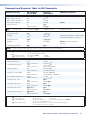
Using the Command and Response Table ..... 20
Common symbol definitions........................... 20
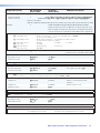
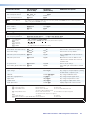
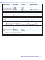
Command and Response Table for
SIS Commands ................................................ 22
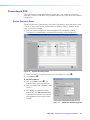
Configuration Software .............................26
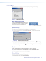
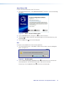
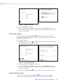
Software/Firmware Installation ........................... 26
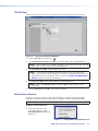
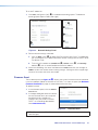
Connecting to PCS ............................................ 28
Device Discovery Panel .................................. 28
TCP/IP Panel ................................................. 29
Offline Device Preview .................................... 29
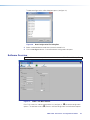
Software Overview ............................................. 30
Software Menu .............................................. 31
Device Menu.................................................. 33
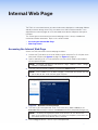
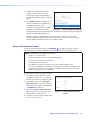
Internal Web Page ..................................... 35
Accessing the Internal Web Page ...................... 35
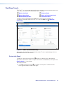
Web Page Panels .............................................. 36
Device Info Panel ........................................... 36
Device Status Panel ....................................... 37
Network Settings Panel ................................. 37
Firmware Panel .............................................. 38
Roles and Permissions Panel ......................... 39
LinkLicense Panel .......................................... 40
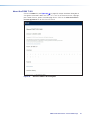
About the FOX3T201 ................................... 41
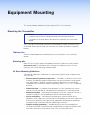
Equipment Mounting ................................. 42
Mounting the Transmitter ................................... 42
Tabletop Use ................................................. 42
Mounting kits ................................................. 42
UL Rack-Mounting Guidelines ....................... 42

FOX3 T 201 Transmitter • Contents viii

FOX3 T 201 Transmitter • Introduction 1
Introduction
WARNING: The FOX3T201 output continuous invisible light (Class 1 rated),
which may be harmful to the eyes; use with caution.
AVERTISSEMENT : Le FOX3T201 émet une lumière invisible en continu (conforme à
la classe1) qui peut être dangereux pour les yeux, à utiliser avec précaution.
• Do not look into the rear panel fiber optic cable connectors or into the fiber optic
cables themselves.
• Ne regardez pas dans les connecteurs de câble fibre optique sur le panneau
arrière ou dans les câbles fibre optique eux-mêmes.
• Plug the attached dust cap into the optical transceiver when the fiber optic cable is
unplugged.
• Branchez la protection contre la poussière dans l’ensemble émetteur/récepteur
lorsque le câble fibre optique est débranché.
About this Guide
This guide contains information about the Extron FOX3T201 fiber optic transmitter.
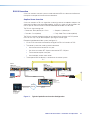
Product Description
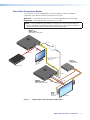
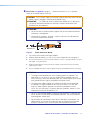
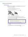
The FOX3T201 transmitter is a ultra-high performance fiber optic extender for long haul
transmission of the following over two fiber optic cables (see figure1 on page2):
• Uncompressed or visually lossless HDCP-compliant 4096x2160 or 3840x2160 (UHD)
@60Hz video HDMI video
• 2-CH LPCM audio
• RS-232 and IR control signals
The transmitter extends HDMI signals up to:
• 20 km (12.4 miles) for the singlemode cables
• 500 m (1640 feet) with 50 µm OM4 4700 MHz bandwidth laser optimized multimode
cables
(see Fiber Cable Transmission Modes on page2).
The transmitter converts the HDMI video, the selected audio, and the RS-232 serial
communication into two proprietary data streams and outputs them as optical signals via
fiber optic small form factor pluggable (SFP) modules on two LC connector to a compatible
Extron FOX3 fiber optic receiver.
The transmitter has many controls, including audio adjustments, that are available under
Remote RS-232 and USB port Simple Set Instruction (SIS) control and PCS.
NOTE: The FOX3 products are not compatible with legacy FOX, FOXBOX, FOX II,
PowerCage 401 FOX, or PowerCage 1600 FOX products.

FOX3 T 201 Transmitter • Introduction 2
Fiber Cable Transmission Modes
The transmitter is further categorized by the type of fiber optic cable, multimode or
singlemode, which defines the effective range of transmission:
Multimode — Long distance, up to 500 m (1640 feet) (depending on the fiber cable)
Singlemode — Very long distance, up to 20 km (12.4 miles)
NOTE: The multimode and singlemode units are physically and functionally identical,
with the exception of the effective range of transmission. In this guide, any reference
applies to either transmission mode unless otherwise specified.
RS-232
REMOTE
POWER
12V
0.7 A MAX
Tx Rx G
A
OUT IN
B
OUT IN
LAN
RS-232
Tx
Rx
Tx RxG
IR
HDMI
FOX3 SR 201
R
AUDIO
CONTROL
OUTPUTS
CONTROL
RS
-232
REMOTE
POWER
12V
--A MAX
Tx
Rx G
A
OUT IN
B
OUT IN
RS-232
Tx
Rx Tx RxG
IR
HDMI
FOX3 T 201
R
AUDIO
CONTROL
INTPUTS
LOOP OUT
LAN
S
T
A
NDBY
CLASS 2 WI
R
IN
G
1
2
X
PA
1002
LEV
EL
1
1
2
1
2
L
I
M
I
T
ER
/
P
R
OT
ECT
SI
GN
A
L
2
I
NP
UTS
OUT
P
UT
R
E
M
O
T
E
0
0
V
OL
/
M
UT
E
10
V
5
0
m
A
1
0
0
-
2
4
0
V
1
.
3
A,
5
0
-
6
0
Hz
Ethernet
Ethernet
HDMI
Loop out
HDMI
Output
HDMI Input
Extron
SI 28
Surface-mount
Speakers
Extron
XPA 1002
Power Amplier
4K Display
Blu-ray Player
Local
Monitor
4K
Up to 20 km (12.43 miles)
Singlemode Fiber
SM Model
Audio
Output
RS-232
Extron
FOX3 T 201
Fiber Optic Transmitter
Extron
FOX3 SR 201
Fiber Optic Receiver
LAN
MODE
L
80
Figure 1. Typical FOX3T201 Transmitter Application
1

FOX3 T 201 Transmitter • Introduction 3
Extron LinkLicense
An Extron LinkLicense unlocks features that add convenience, expand system options, and
enhance the capabilities of Extron products. Each LinkLicense can be purchased separately
from the FOX3 device and activated as the need arises (A LinkLicense can be uploaded
using Extron Toolbelt software and the Toolbelt Help File. See Software/Firmware
Installation on page26 to download Toolbelt).
LinkLicense upgrades available for the FOX3 transmitter include the following:
• Uncompressed Video Upgrade —
• This LinkLicense is enabled once and lasts for the life of the product.
• Allows the FOX3 devices to pass uncompressed 4K @ 60 Hz video on the second
SFP module, enabling the highest video performance.
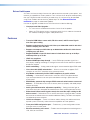
Features
• Transmits HDMI video, stereo audio, RS-232 control, and IR control signals
over fiber optic cabling.
• Supports mathematically lossless 4K video up to 4096x2160 at 60 Hz with 4:4:4
chroma sampling over one fiber.
• Supports uncompressed 4K video up to 4096x2160 at 60 Hz with 4:4:4 chroma
sampling over two fibers.
• Supported HDMI 2.0 specification features include data rates up to 18 Gbps
and Deep Color up to 12-bit.
• HDCP 2.3 compliant.
• Buffered HDMI input loop-through — Local HDMI output provides signals for a
local display, enabling monitoring or sharing of content without the need for a separate
distribution amplifier.
• Audio embedding — Analog stereo audio signals are converted to digital HDMI audio.
• User-selectable HDCP authorization — Allows the transmitter to appear HDCP
compliant or non-HDCP compliant to the connected source.
• Key Minder continuously verifies HDCP compliance for quick, reliable
switching — Authenticates and maintains continuous HDCP encryption between
input and output devices to ensure quick and reliable switching in professional AV
environments.
• EDID Minder automatically manages EDID communication between connected
devices — EDID Minder ensures that all sources power up properly and reliably output
content for display.
• Audio gain and attenuation adjustment capability — Setting the level of gain or
attenuation eliminates noticeable volume differences when switching between sources.
• Bidirectional RS-232 and IR signal transmission over fiber optic cabling for AV
device control — Bidirectional RS-232 and IR control pass-through enables a remote
device to be controlled without the need for additional cabling. Two fibers are required
for bidirectional communications.
• LinkLicense Support — Extron LinkLicense unlocks features that add convenience,
expand system functionality, and enhance the capabilities of Extron products.
• Front panel USB configuration port — Enables easy system configuration without
having to access the rear panel.
• Ethernet monitoring and control — Enables control and proactive monitoring over a
LAN, WAN, or the Internet.

FOX3 T 201 Transmitter • Introduction 4
• RS-232 control — Features an RS-232 serial port for control and configuration.
• Real-time status LED indicators for troubleshooting and monitoring — Front
and rear panel LEDs verify signal presence, HDCP authentication, fiber link status, and
power.
• Easy setup and commissioning with Extron’s PCS - Product Configuration
Software — Conveniently configures multiple products using a single software
application.
• Internal color bars test pattern for calibration and setup — Simplifies setup and
installation by providing a video signal when a source is unavailable.
• Compatible with Extron FOX3 Series matrix switchers — Creates HDCP-
compliant signal distribution systems.
• JITC Certified — Successfully completed interoperability and information assurance
testing for use in government applications and other mission-critical environments.
• Industry standard LC connectors provide reliable physical connectivity and
precise fiber core alignment.
• Available as an 850 nm multimode model for moderate-range transmissions up
to 500 m (1640 feet) and a 1310 nm singlemode model for extreme distances up
to 20 km (12.4 miles).
• 1" (2.5 cm) high, half rack width mountable metal enclosure.
• External Extron Everlast power supply — Provides worldwide power compatibility,
with high demonstrated reliability and low power consumption for reduced operating
cost.
• Extron Everlast Power Supply is covered by a 7-year parts and labor warranty.

FOX3 T 201 Transmitter • Installation and Operation 5
Installation and
Operation
This section details the installation of the FOX3T201 transmitter, including:
• Installation Overview
• Rear Panel Features
• Connector and Cable Details
• Front Panel Features
• Operation
• Audio Configuration
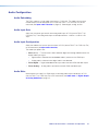
Installation Overview
Follow these steps to install and set up an Extron FOX3T201 transmitter for operation:
c
Turn off all of the equipment. Ensure that the video source and the output display are all
turned off and disconnected from the power source.
c
Mount the transmitter (see Equipment Mounting on page42).
c
Connect the cables and configure the units (see “Rear Panel Connections”, starting
below).
c
Plug in the power supplies, then turn on the display and the input.
Rear Panel Features
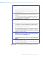
Rear Panel Connections
RS-232
REMOTE
POWER
12V
--A MAX
Tx Rx G
A
OUTIN
B
OUTIN
RS-232
Tx Rx Tx RxG
IR
HDMI
FOX3 T 201
R
AUDIO
CONTROL
INTPUTS
J
J
JH
H
HG
G
GC
C
CA
A
A
E
E
E
I
I
I
F
F
F
B
B
B
D
D
D
LOOP OUT
LAN
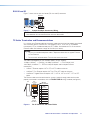
Figure 2. FOX3T201 Transmitter Rear Panel Features
A
Power inlet
F
Control RS-232/IR port
B
Power LED
G
Remote RS-232
C
Audio input
H
LAN Ethernet port
D
HDMI input
I
SFP module and LEDs
E
HDMI Loop Out
J
Reset button
2

FOX3 T 201 Transmitter • Installation and Operation 6
A
Power inlet (see figure2 on page5) — Connect the external 12 V, 2.0 A power
supply to the 2-pole captive screw inlet.
CAUTION: The DC output cables must be kept separate from each other while the
power supply is plugged in. Remove power before wiring
ATTENTION : Les câbles de sortie CC doivent être séparés les uns des autres
tant que la source d’alimentation est branchée. Coupez l’alimentation avant
d’effectuer les raccordements.
ATTENTION:
• Do not connect any external power supplies until you have read the Attention
notifications starting below.
• Veuillez lire les encadrés « Attention » à partir ci-dessous avant de brancher
une source d’alimentation externe.
SECTION A–A
Ridges
Smooth
A
A
3/16"
(5 mm) Max.
POWER
12V
--A MAX
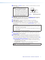
Figure 3. Power Connector Wiring
1. Cut the DC output cord to the length needed.
2. Strip the jacket to expose 3/16inch (5mm) of the conductor wire (see figure3).
3. Ensure the connections have the correct polarity as shown in the figure above. The wire
with ridges is the ground wire.
4. Slide the exposed ends of the wire into the captive screw connector and secure by
tightening the screws.
5. Use the supplied tie wrap to strap the power cord to the extended tail of the connector.
ATTENTION:
• The length of the exposed wires in the stripping process is important. The
ideal length is 3/16 inches (5 mm). Any longer and the exposed wires may
touch, causing a short circuit between them. Any shorter and the wires can be
easily pulled out even if tightly fastened by the captive screws.
• La longueur des câbles exposés est importante lorsque l’on entreprend de
les dénuder. La longueur idéale est de 5 mm (3/16 inches). S’ils sont trop
longs, les câbles exposés pourraient se toucher et provoquer un court-
circuit. S’ils sont trop courts, ils peuvent être tirés facilement, même s’ils sont
correctement serrés par les borniers à vis.
• Do not tin the wire leads before installing into the connector. Tinned wires are
not as secure in the connector and could be pulled out. They may also break
after being bent several times.
• Ne pas étamer les conducteurs avant de les insérer dans le connecteur. Les
câbles étamés ne sont pas aussi bien fixés dans le connecteur et pourraient
être tirés. Ils peuvent aussi se casser après avoir été pliés plusieurs fois.
3

FOX3 T 201 Transmitter • Installation and Operation 7
ATTENTION:
• Always use a power supply provided by or specified by Extron. Use of an
unauthorized power supply voids all regulatory compliance certification and
may cause damage to the supply and the end product.
• Utilisez toujours une source d’alimentation fournie ou recommandée par
Extron. L’utilisation d’une source d’alimentation non autorisée annule toute
certification de conformité réglementaire, et peut endommager la source
d’alimentation et l’unité.
• If not provided with a power supply, this product is intended for use with a
UL Listed power source marked “Class 2” or “LPS” rated 12 VDC, 2.0 A
minimum.
• Si le produit n’est pas fourni avec une source d’alimentation, il doit être utilisé
avec une source d’alimentation certifiée UL de classe 2 ou LPS avec une
tension nominale de 12 Vcc, 2.0 A minimum.
• Unless otherwise stated, the AC/DC adapters are not suitable for use in air
handling spaces or in wall cavities.
• Sauf mention contraire, les adaptateurs CA/CC ne conviennent pas à une
utilisation dans les espaces d’aération ou dans les cavités murales.
• The installation must always be in accordance with the applicable provisions
of National Electrical Code ANSI/NFPA 70, article 725 and the Canadian
Electrical Code part 1, section 16. The power supply shall not be permanently
fixed to building structure or similar structure.
• Cette installation doit toujours être conforme aux dispositions applicables du
Code américain de l’électricité (National Electrical Code) ANSI/NFPA 70, article
725, et du Code canadien de l’électricité, partie1, section16. La source
d’alimentation ne devra pas être fixée de façon permanente à une structure de
bâtiment ou à une structure similaire.
• Power supply voltage polarity is critical. Incorrect voltage polarity can damage
the power supply and the unit. The ridges on the side of the cord identify the
power cord negative lead (see figure3 on page6).
• La polarité de la source d’alimentation est primordiale. Une polarité incorrecte
pourrait endommager la source d’alimentation et l’unité. Les stries sur le côté
du cordon permettent de repérer le pôle négatif du cordon d’alimentation (voir
figure3).
• To verify the polarity before connection, plug in the power supply with no load
and check the output with a voltmeter.
• Pour vérifier la polarité avant la connexion, brancher l’alimentation hors charge
et mesurer sa sortie avec un voltmètre.
B
Power LED — The lit LED indicates power is applied and device is ready to transmit.

FOX3 T 201 Transmitter • Installation and Operation 8
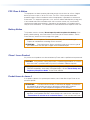
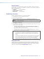
C
Audio input (see figure2 on page5)— Connect an audio input device to the Audio
3.5 mm audio jack.
NOTE: The analog audio input on this
connector is in addition to the digital
audio embedded in the HDMI inputs. See
figure4 to identify the connector tip, ring,
and sleeve when making connections for
the transmitter from existing audio cables.
A mono audio connector consists of the
tip and sleeve. A stereo audio connector
consists of the tip, ring, and sleeve.
Sleeve ( )
Ring (
-
)
Tip (+)
3.5 mm Stereo Plug Connector
(balanced)
Figure 4. Audio Wiring Diagram
D
HDMI input — Connect a digital video input to this HDMI port. The transmitter also
accepts embedded digital audio on this port (see HDMI Connectors on page10 to
use the included Extron Lock-It Lacing Bracket).
E
HDMI Loop Out — If desired, connect a local monitor to this HDMI port.
F
Control RS-232 and IR port — Connect a serial RS-232 signal, a modulated
or unmodulated IR signal, or both to this 3.5 mm, 5-pole captive screw port for
bidirectional RS-232 and IR communication (see RS-232 and IR on page11 to wire
the connector).
NOTES:
• To receive responses from the controlled device over RS-232 or IR, two fiber
optic cables must be connected.
• The FOX3 system can pass RS-232 commands and responses at rates up to
115200 baud.
• RS-232 and IR can be active simultaneously.
G
Remote RS-232 port — For serial control of the transmitter, connect a host device,
such as a computer or touch panel control, via the 3-pole captive screw port (see
RS-232 and IR to wire this connector).
H
LAN Ethernet port — Connect the transmitter to an Ethernet LAN or WAN via this
RJ-45 port. Ethernet control allows the operator to configure the transmitter from a
remote location. When connected to an Ethernet LAN or WAN, the transmitter can be
accessed and operated from a computer running a standard Internet browser (see TP
Cable Termination and Recommendations on page11 to wire the connector).
• Link (green) LED — Indicates that the unit is properly connected to an Ethernet
LAN. This LED should light steadily.
• Act (yellow) LED — Indicates transmission of data packets on the RJ-45
connector. This LED should blink as the unit communicates.
NOTE: This is not a pass-through LAN connection
4

FOX3 T 201 Transmitter • Installation and Operation 9
I
SFP module and LEDs — (see figure2 on page5)
WARNING: The units output continuous invisible light (Class 1 rated), which
may be harmful to the eyes; use with caution. Plug the attached dust cap into the
optical transceiver when the fiber optic cable is unplugged.
AVERTISSEMENT : Le produit émet une lumière invisible en continu (conforme
à la classe1) qui peut être dangereux pour les yeux, à utiliser avec précaution
Branchez la protection contre la poussière dans l’ensemble émetteur/récepteur
lorsque le câble fibre optique est débranché.
NOTES:
• Ensure the proper fiber cables for the transmitter and receiver pair are used.
Typically, singlemode fiber has a yellow jacket and multimode cable has an
orange or aqua jacket.
• See figure5 for fiber cable connections. Connect the transmitter to a receiver
in one of three ways:
• One way (transmitter to receiver) only, connect transmitter Outputs A (
1
) to
receiver Inputs A (
1
).
• Two way (transmitter to receiver and return), connect transmitter Outputs
A (
1
) to receiver Inputs A (
1
) and connect transmitter Outputs A (
2
) to
receiver Inputs A (
2
).
• Output B is available to transmit a 4K @ 60 Hz uncompressed signal when
the FOX3 4K @ 60 Hz Uncompressed Video LinkLicense is purchased.
1
Port A Out (required) — For all one-way video, audio,
and serial communications from the transmitter to the
receiver, connect a fiber optic cable to the Out LC port.
Connect the opposite end of this fiber optic cable to
the Port A In LC port on the receiver or to any other
compatible Extron FOX3 device.
2
Port A In (optional) — For one-way serial
communications from the receiver to the transmitter,
connect a fiber optic cable to the In LC port.
Connect the opposite end of this fiber optic cable to
the Port A Out LC port on a receiver or to any other
compatible Extron FOX3 device.
SFP Link LEDs —
Receiver
T
ransmitter
11
22
22
11
A
OUTIN
OUTPUTS
B
OUTIN
A
OUTIN
INPUTS
B
OUTIN
Figure 5. Connection
• Transmit Optical OUT LED lights solid green when powered and lights off when
there is no power on the endpoint.
• Receive Optical IN LED lights solid green when light is present and lights off
when there is no power or light present.
J
Reset button — Initiates three levels of resets (1, 4, and 5). Use a pointed stylus,
ballpoint pen, or small screwdriver to access the recessed button (see Reset on
page12 for detailed reset information).
5

FOX3 T 201 Transmitter • Installation and Operation 10
Connector and Cable Details
HDMI Connectors
HDMI signals run at a very high frequency and are especially prone to errors caused by bad
video connections, too many adapters, or excessive cable length. To avoid the loss of an
image or jitter, follow these guidelines:
• Limit or avoid the use of adapters.
• Use only cables specifically intended for HDMI or DVI signals.
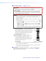
To securely fasten an HDMI cable to a device:
1. Plug the HDMI cable into the panel connection (see figure6,
1
).
3
33
11
44
55
22
Figure 6. Installing the LockIt Lacing Bracket
2. Loosen the HDMI connection mounting screw from the panel enough to allow the
LockIt lacing bracket to be placed over it (
2
). The screw does not have to be removed.
3. Place the LockIt lacing bracket on the screw and against the HDMI connector, then
tighten the screw to secure the bracket (
3
).
ATTENTION:
• Do not overtighten the HDMI connector mounting screw. The shield to which it
fastens is very thin and can easily be stripped.
• Ne serrez pas trop la vis de montage du connecteur HDMI. Le blindage auquel
elle est attachée est très fin et peut facilement être dénudé.
4. Loosely place the included tie wrap around the HDMI connector and the LockIt lacing
bracket (
4
).
5. While holding the connector securely against the lacing bracket, use pliers or similar
tools to tighten the tie wrap, then remove any excess length (
5
).
6

FOX3 T 201 Transmitter • Installation and Operation 11
RS-232 and IR
Figure 7 shows how to wire the Control (RS-232 and IR) connector.
TxRx
RxTx
Gnd
Gnd
IR Device
RS-232 Device
RxTx RxTxG
RS-232 IR
CONTROL
Figure 7. Control and Sync Connectors Wiring
NOTE: The IR Tx and Rx line pair and the RS-232 Tx and Rx line pair must each cross
once between this connector and the source or destination.
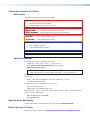
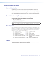
TP Cable Termination and Recommendations
It is vital that your Ethernet cable be the correct cable type and that it be properly terminated
with the correct pinout. Ethernet links use Category (CAT) 3, 5e, or CAT 6, unshielded
twisted pair (UTP) or shielded twisted pair (STP) cables, terminated with RJ-45 connectors.
Ethernet cables are limited to a length of 328 feet (100 meters).
NOTES:
• Do not use standard telephone cables. Telephone cables do not support Ethernet
or Fast Ethernet.
• Do not stretch or bend cables. Transmission errors can occur.
The cable used depends on your network speed. The unit supports
10 Mbps (10Base-T — Ethernet), 100 Mbps (100Base-T — Fast Ethernet), and
1000Mbps(1000Base-T — IEEE 802.3ab) half-duplex and full-duplex Ethernet
connections.
• 10Base-T Ethernet requires CAT 3 UTP or STP cable at minimum.
• 100Base-T Fast Ethernet requires CAT 5e UTP or STP cable at minimum.
• 1000Base-T Gigabit Ethernet requires CAT 5, CAT 5e, CAT 6, or CAT 7 UTP or STP
cable.
The Ethernet cable must be terminated as a patch (straight-through) cable and must be
properly terminated in accordance with the TIA/EIA T568-B wiring standard (see figure8).
5
Pin
1
2
3
6
7
8
4
Side
12345678
Insert
Twisted
Pair Wires
Pins:
RJ-45
Connector
Wire color
White-green
Green
White-orange
White-blue
Orange
White-brown
Brown
Blue
TIA/EIA T
568 B
Figure 8. RJ-45 Connector and Pinout Tables
7
8

FOX3 T 201 Transmitter • Installation and Operation 12
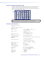
Front Panel Features
FOX3 T 201
CONFIG
INPUT
SIGNAL
HDCP
DIGITAL AUDIO
ANALOG AUDIO
A
A
A C
C
CB
B
B
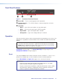
Figure 9. Transmitter Front Panel Features
A
Power LED — The unit is receiving power and is operational.
B
Configuration port — This USB mini-B port is used to configure the unit and to
update firmware.
C
Input LEDs
• Signal — Lights when the unit detects an input video signal.
• HDCP — Lights when the input signal is HDCP encrypted.
• Digital Audio — Lights when digital audio is selected.
• Analog Audio — Lights when analog audio input is selected.
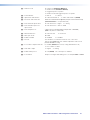
Operation
After the transmitter, receiver, and the connected devices are powered up, the system is fully
operational. If any problems are encountered, ensure all cables are routed and connected
properly.
NOTE: Ensure that the video source and display are properly connected to the FOX3
transmitter and receiver, and power is applied to the FOX3 devices and the display
before power is applied to the video source. If the other devices are not turned on
before the video source, the image may not appear.
Configuration and operation of the transmitter is accomplished via SIS Configuration
and Control starting on page17, the Internal Web Page starting on page35, and
Configuration Software starting on page26.
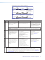
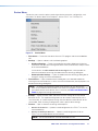
Reset
The rear panel Reset button initiates three levels of resets (numbered 1, 4, and 5). Use a
pointed stylus, ballpoint pen, or small screwdriver to access the recessed button.
See the Reset Modes and figure10 on page13 for a summary of the resets.
ATTENTION:
• Review the reset modes carefully. Some reset modes delete all user loaded
content and revert the device to default configuration.
• Analysez minutieusement les différents modes de réinitialisation. Certains modes
de réinitialisation suppriment l’intégralité du contenu chargé de l’utilisateur et
remettent l’appareil au mode de configuration par défaut.
9
La page est en cours de chargement...
La page est en cours de chargement...
La page est en cours de chargement...
La page est en cours de chargement...
La page est en cours de chargement...
La page est en cours de chargement...
La page est en cours de chargement...
La page est en cours de chargement...
La page est en cours de chargement...
La page est en cours de chargement...
La page est en cours de chargement...
La page est en cours de chargement...
La page est en cours de chargement...
La page est en cours de chargement...
La page est en cours de chargement...
La page est en cours de chargement...
La page est en cours de chargement...
La page est en cours de chargement...
La page est en cours de chargement...
La page est en cours de chargement...
La page est en cours de chargement...
La page est en cours de chargement...
La page est en cours de chargement...
La page est en cours de chargement...
La page est en cours de chargement...
La page est en cours de chargement...
La page est en cours de chargement...
La page est en cours de chargement...
La page est en cours de chargement...
La page est en cours de chargement...
La page est en cours de chargement...
-
 1
1
-
 2
2
-
 3
3
-
 4
4
-
 5
5
-
 6
6
-
 7
7
-
 8
8
-
 9
9
-
 10
10
-
 11
11
-
 12
12
-
 13
13
-
 14
14
-
 15
15
-
 16
16
-
 17
17
-
 18
18
-
 19
19
-
 20
20
-
 21
21
-
 22
22
-
 23
23
-
 24
24
-
 25
25
-
 26
26
-
 27
27
-
 28
28
-
 29
29
-
 30
30
-
 31
31
-
 32
32
-
 33
33
-
 34
34
-
 35
35
-
 36
36
-
 37
37
-
 38
38
-
 39
39
-
 40
40
-
 41
41
-
 42
42
-
 43
43
-
 44
44
-
 45
45
-
 46
46
-
 47
47
-
 48
48
-
 49
49
-
 50
50
-
 51
51


dans d''autres langues
- English: Extron FOX3 T 201 User manual
Documents connexes
-
Extron FOX3 T 201 Manuel utilisateur
-
-
-
-
-
-
Extron FOX3 SR 301 Manuel utilisateur
-
-
-
Autres documents
-
Nyrius NPCS550V1 Guide de démarrage rapide
-
Lindy 8x8 HDMI 4K60 Matrix Manuel utilisateur
-
BenQ C30TH InstaShow X Button Manuel utilisateur
-
WTI REM Series Guide de démarrage rapide
-
Binary B-660-MTRX-4x4 Guide d'installation
-
Leviton 41910-U2B Mode d'emploi
-
Sagem 3100MFP Le manuel du propriétaire
-
Nice Automation TT6 Le manuel du propriétaire
-
NovaStar CVT4K-M Mode d'emploi
-
 S.R.Smith 6004 Fiber Optic Illuminator Guide d'installation
