KitchenAid W11496339A Manuel utilisateur
- Catégorie
- Fours
- Taper
- Manuel utilisateur

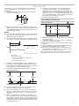
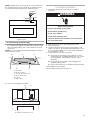
MICROWAVE HOOD COMBINATION
INSTALLATION INSTRUCTIONS
This product is suitable for use above electric or gas cooking products up to and including 36" (91.4 cm) wide. See the “Installation
Requirements” section for further notes.
These installation instructions cover different models. The appearance of your particular model may differ slightly from the illustration
in these installation instructions.
INSTRUCTIONS D’INSTALLATION
DE L’ENSEMBLE FOUR À MICRO-ONDES/HOTTE
Ce produit est conçu pour l’utilisation au-dessus d’appareils de cuisson électriques ou à gaz de 36 po (91,4 cm) de largeur ou moins.
Voir la section « Exigences d’installation » pour d’autres remarques.
Ces instructions d’installation sont valables pour plusieurs modèles. Il se peut que l’apparence de votre propre modèle soit légèrement
différente de celle montrée sur les illustrations dans ce document.
Table of Contents/Table des matières
W11496339A
MICROWAVE HOOD COMBINATION SAFETY ............................2
INSTALLATION REQUIREMENTS .................................................2
Tools and Parts .............................................................................2
Separate Cardboard Template .....................................................3
Location Requirements ................................................................3
Product Dimensions .....................................................................3
Electrical Requirements ...............................................................4
INSTALLATION INSTRUCTIONS ...................................................5
Remove Mounting Plate ...............................................................5
Rotate Blower Motor ....................................................................5
Locate Wall Stud(s) ......................................................................8
Mark Rear Wall .............................................................................9
Drill Holes in Rear Wall ...............................................................10
Attach Mounting Plate to Wall ...................................................10
Prepare Upper Cabinet ..............................................................11
Install Damper Assembly
(for wall venting only) ..................................................................11
Install the Microwave Oven ........................................................12
Complete Installation .................................................................13
VENTING DESIGN SPECIFICATIONS ........................................14
ASSISTANCE ................................................................................15
Replacement Parts .....................................................................15
Accessories ................................................................................15
SÉCURITÉ DE L’ENSEMBLE FOUR À
MICRO-ONDES/HOTTE...............................................................16
EXIGENCES D’INSTALLATION ...................................................16
Outillage et pièces ......................................................................16
Gabarit en carton séparé ...........................................................17
Exigences d’emplacement .........................................................17
Dimensions du produit ...............................................................18
Spéci cations électriques ..........................................................18
INSTRUCTIONS D’INSTALLATION .............................................19
Dépose de la plaque de montage ..............................................19
Réorientation du moteur du ventilateur .....................................19
Identi er la position du/des poteau(x) du colombage mural .....22
Tracé sur le mur arrière ..............................................................23
Perçage de trous dans le mur arrière .........................................24
Fixation de la plaque de montage sur le mur ............................24
Préparation du placard supérieur ..............................................25
Installation du module du clapet anti-re ux
(pour décharge à travers le mur uniquement) ............................25
Installation du four à micro-ondes .............................................26
Achever l’installation ..................................................................28
SPÉCIFICATIONS/CONCEPTION DU CIRCUIT
D’ÉVACUATION ...........................................................................28
ASSISTANCE ................................................................................30
Pièces de rechange ....................................................................30
Accessoires ................................................................................30

2
MICROWAVE HOOD COMBINATION SAFETY
INSTALLATION REQUIREMENTS
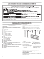
Tools and Parts
Tools Needed
Gather the required tools and parts before starting installation.
Read and follow the instructions provided with any tools listed
here.
■Measuring tape
■Pencil
■Masking tape or thumbtacks
■Scissors
■No. 2 Phillips screwdriver
■No. 3 Phillips screwdriver
for 1/4-20 x 3" (7.6 cm) bolts
■Drill
■3/16" (5 mm), 3/8" (1cm),
5/8" (1.6 cm) drill bits
■3/4" (1.9 cm) hole saw
■Diagonal wire cutting pliers
■Stud nder
■7⁄16" (1.1 cm) socket wrench (or box wrench) for 1/4" x 2"
(6.4 mm x 5.1cm) lag screws
■11/2" (3.8 cm) diameter hole drill bit for wood or metal cabinet
■Keyhole saw
■Caulking gun and weatherproof caulking compound
■Duct tape
Parts Needed
For information on reordering, see the “Replacement Parts”
section.
NOTE: The hardware items listed here are for wood studs.
For other types of wall structures, be sure to use appropriate
fasteners.
NOTE: Depending on model, aluminum grease lter and
charcoal lter may be combined.
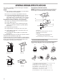
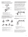
Materials Needed
Standard ttings for wall or roof venting. See the “Venting Design
Speci cations” section.
A BCDEF
G
H
A. 3/16-24 x 3" round-head
bolts (2)
B. 1/4-20 x 3" at-head bolts (2)
C. Washers (2)
D. 3/16" toggle nuts (2)
E. 1/4" x 2" lag screws (2)
F. #6 x 3/8" Sheet metal screws (2)
G. Power supply cord bushing (1)
H. Damper assembly (for wall or
roof venting)
Not Shown:
■Mounting plate (attached to
back of microwave oven)
■Cardboard template (part of
packaging)
■Aluminum grease lters
■Charcoal lters (Depending
on model, charcoal lters may
not be included. See User
Instructions.)

3
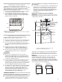
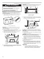
Separate Cardboard Template
The wall template and upper cabinet template is embedded in
the backside of the carton box. They are used as a rear wall
template and upper cabinet template.
1. Cut along the dotted line to separate the cardboard template
from the backside of the carton box.
2. Set the cardboard template to the side and refer to it during
the “Mark Rear Wall” and “Prepare Upper Cabinet” parts of
installation.
Location Requirements
Check the opening where the microwave oven will be installed.
The location must provide:
■Minimum installation dimensions. See the “Installation
Dimensions” illustration.
■Minimum one 2" x 4" (5.1 x 10.2 cm) wood wall stud and
minimum 3/8" (1 cm) thickness drywall or plaster/lath within
cabinet opening.
■Support for weight of 150 lbs (68 kg) which includes
microwave oven and items placed inside the microwave
oven and upper cabinet.
■Grounded electrical outlet inside upper cabinet. See the
“Electrical Requirements” section.
NOTES:
■If installing the microwave oven near a left sidewall, make
sure there is at least 6" (15.2 cm) of clearance between the
wall and the microwave oven so that the door can open fully.
■Some models have a pocket handle. If installing the
microwave near a right side wall, make sure there is at least
3" (7.6 cm) of clearance between wall and microwave oven
so you can grab the handle integrated inside the door.
■Some cabinet and building materials are not designed to
withstand the heat produced by the microwave oven for
cooking. Check with your builder or cabinet supplier to make
sure that the materials used will not discolor, delaminate, or
sustain other damages.
Special Requirements
For Wall Venting Installation Only:
■Cutout must be free of any obstructions so that the vent t
properly and the damper blade opens freely and fully.
For Roof Venting Installation Only:
■If you are using a rectangular-to-round transition piece, the
3" (7.6 cm) clearance needs to exist above the microwave
oven so that the damper blade can open freely and fully.
See “Rectangular to Round Transition” illustration in the
“Venting Design Speci cations” section.
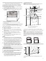
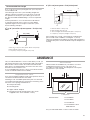
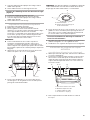
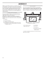
Installation Dimensions
NOTE: The grounded 3 prong outlet must be inside the upper
cabinet. See the “Electrical Requirements” section.
*30" (76.2 cm) is typical for 66" (167.6 cm) installation height.
Exact dimensions may vary depending on type of range/cooktop
below.
NOTE: To ensure good performance, do not obstruct top vent
air ow. If cabinets are deeper than 14" (35.6 cm) but no more
than 15" (38.1 cm), use the bump out mounting kit replacing the
I bar mounting plate from the wall. The bump out mounting kit
(part # W11185746) is not provided but can be purchased from
Whirlpool.
Product Dimensions
*Overall depth of product will vary slightly depending on door
design.
A. 2" x 4" (5.1 x 10.2 cm) wall stud
B. Grounded 3 prong outlet
12" (30.5 cm) minimum
14" (35.6 cm) maximum
30"
(76.2 cm)
minimum
AB
upper cabinet and
side cabinet depth
30"
(76.2 cm)
typical*
66" (167.6 cm) minimum
I bar mounting plate
Bump out mounting bracket
12" DEEPER 14" 14" DEEPER 15"
16
¹⁄₄
"
(41.3 cm)
17
¹⁄₈
"
(43.5 cm)
+/-
3/16
(0.5 cm)
17"
Up to
(43.2 cm)*
cm)
29
⁷⁄₈
" (76.0
"
12 1/2" (31,8 cm)
6 1/4" (15,9 cm)
5 3/4"
(14,6 cm)
4 3/4
"
(12,1 cm)
10"
(25,4 cm)
12 1/2" (31,8 cm) 7 1/2" (19,1 cm)
6 3/8" (16,2 cm)
15 5/8
"
(39,71 cm)
15 5/8"
(39,71 cm)
6 1/2
"
(16,5 cm)
14 1/6" (35.96 cm) 14 1/6" (35.96 cm)
G
DE
AB
F
12 1/2
"
(31,8 cm)
6 1/4
"
(15,9 cm)
5 3/4
"
(14,6 cm)
4 3/4
"
(12,1 cm)
10
"
(25,4 cm)
12 1/2
"
(31,8 cm)
7 1/2
"
(19,1 cm)
6 3/8
"
(16,2 cm)
15 5/8
"
(39,71 cm)
15 5/8
"
(39,71 cm)
6 1/2
"
(16,5 cm)
14 1/6
"
(35.96 cm)
14 1/6
"
(35.96 cm)
G
D
D
E
A
B
F
B
A
A. Backside of the carton box
B. Cardboard template (including Rear Wall template and Upper
Cabinet template)

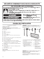
4
Electrical Requirements
Observe all governing codes and ordinances.
Required:
■A 120 V, 60 Hz, AC only, 15 or 20 A electrical supply with a
fuse or circuit breaker
Recommended:
■A time-delay fuse or time-delay circuit breaker
■A separate circuit serving only this microwave oven
GROUNDING INSTRUCTIONS
SAVE THESE INSTRUCTIONS
For all cord connected appliances:
The microwave oven must be grounded. In the event of
an electrical short circuit, grounding reduces the risk of
electric shock by providing an escape wire for the electric
current. The microwave oven is equipped with a cord
having a grounding wire with a grounding plug. The plug
must be plugged into an outlet that is properly installed
and grounded.
WARNING: Improper use of the grounding plug can
result in a risk of electric shock. Consult a qualified
electrician or serviceman if the grounding instructions are
not completely understood, or if doubt exists as to whether
the microwave oven is properly grounded.
Do not use an extension cord. If the power supply cord is
too short, have a qualified electrician or serviceman install
an outlet near the microwave oven.
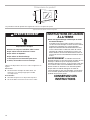
Electrical Shock Hazard
Plug into a grounded 3 prong outlet.
Do not remove ground prong.
Do not use an adapter.
Do not use an extension cord.
Failure to follow these instructions can result in death,
fire, or electrical shock.
WARNING

5
INSTALLATION INSTRUCTIONS
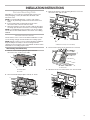
Remove Mounting Plate
Depending on your model, the mounting plate may be in the
foam packaging, or it may be attached to the back of the
microwave oven.
NOTE: To avoid possible damage, cover the work surface.
1. Remove any remaining contents from the microwave oven
cavity.
2. If the mounting plate is attached to the back of the
microwave oven, remove it and set it aside.
3. Tape the microwave oven door closed so that the door does
not swing open while the microwave oven is being handled.
NOTE: To avoid damage to the microwave oven, do not grip or
use the door or door handle while the microwave oven is being
handled.
Rotate Blower Motor
The microwave oven is set for recirculation installation. For wall
or roof venting, changes must be made to the venting system.
NOTE: Skip this section if you are using recirculation installation.
Keep the damper assembly in case the venting method is
changed, or the microwave oven is reinstalled in another location
where wall or roof venting may be used.
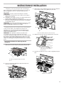
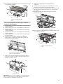
Wall Venting Installation Only
1. Remove screws attaching damper plate to back of
microwave oven, set the screws aside.
2. Turn and hold the damper plate vertically as shown.
3. Remove two blower screws attaching blower motor to the
microwave oven, and set aside.
4. Disconnect the blower motor wire from the connector.
5. Lift blower motor out of microwave oven, and set aside.
A
B
A. Damper plate
B. Screws
A
A. Damper plate
A
A. Blower screws (in recessed holes)
A
B
A. Blower motor wire
B. Connector
A
A. Blower Motor

6
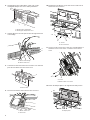
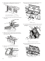
6. Using diagonal wire cutting pliers, gently snip out the
rectangular damper vent covers at the perforations.
7. Hold the blower motor wire, put the wire through the blower
motor bridge.
8. Lower blower motor back into the microwave oven. Exhaust
ports face the back of the microwave oven.
9. Reconnect the blower motor wire into the connector.
10. Reattach the two blower screws into the recessed holes in
the back of the microwave.
11. Check to make sure the two screws are secured properly in
the blower motor screw holes, so that the motor cannot
move.
12. Return the damper plate to its original horizontal position.
B
A
A. Diagonal wire cutting pliers
B. Rectangular damper vent cover
A. Blower motor bridge
B. Blower motor wire
A
B
A. Exhaust Port
A
A
B
A. Blower motor wire
B. Connector
A B
A. Screws
B. Recessed holes
AB
A. Screws
B. Blower motor screw holes
A
A. Damper plate

7
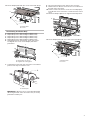
13. Secure damper plate with two screws removed in Step 1.
Roof Venting Installation Only
1. Repeat Step 1 from “Wall Venting Installation Only.”
2. Repeat Step 2 from “Wall Venting Installation Only.”
3. Repeat Step 3 from “Wall Venting Installation Only.”
4. Repeat Step 4 from “Wall Venting Installation Only.”
5. Repeat Step 5 from “Wall Venting Installation Only.”
6. Using diagonal wire cutting pliers, gently snip out the
rectangular vent covers on the damper plate at the
perforations.
7. Lower blower motor back into microwave oven. Exhaust
ports face the top of microwave oven.
IMPORTANT: If blower motor is not positioned with at
side facing the back of the microwave oven (as shown),
performance will be poor.
8. Reconnect the blower motor wire into the connector.
9. Reattach the two blower screws into the recessed holes in
the back of the microwave.
10. Check to make sure the two screws are secured properly
in the blower motor screw holes, so that the motor cannot
move.
11. Return the damper plate to its original horizontal position.
12. Secure damper plate with two screws removed in Step 1.
A
B
A. Damper plate
B. Screws
B
A
A. Rectangular vent covers
B. Diagonal wire cutting pliers
A
A. Exhaust port
A
A. Damper plate
A. Damper plate
B. Screws
A
B

8
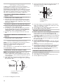
Locate Wall Stud(s)
NOTE: If no wall studs exist within the cabinet opening, do not
install the microwave oven.
See illustrations in “Possible Wall Stud Con gurations.”
1. Using a stud nder, locate the edges of the wall stud(s)
within the opening.
2. Mark the center of each stud, and draw a plumb line down
each stud center. See illustrations in “Possible Wall Stud
Con gurations.”
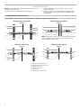
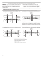
Possible Wall Stud Con gurations
These depictions show examples of preferred installation con gurations with the mounting plate.
No Wall Studs at End Holes
Wall Stud at End Hole
No Wall Studs at End Holes
NOTE: If wall stud is within 6" (15.2 cm) of the vertical centerline
(see the “Mark Rear Wall” section), only recirculation or roof
venting installation can be done.
Wall Studs at End Holes
Figure 1
A
A
B
C
C
D
E
E
F
Figure 3
AA,
D
B
C
E
F
D
E
C
A. End holes (on mounting plate)
B. Cabinet opening vertical centerline
C. Wall stud centerlines
D. Holes for lag screws
E. Support tabs
F. Mounting plate center markers
Figure 2
A
A
B
C
D
E
E
F
Figure 4
A,D
B
E
A,
D
C
E
C
F

9
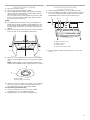
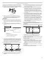
Mark Rear Wall
The microwave oven must be installed on a minimum of one
wall stud, preferably two, using a minimum of one lag screw,
preferably two.
1. Using measuring tape, nd and clearly mark the vertical
centerline of the opening.
2. Align the center markers on the cardboard template, to the
centerline on the wall, making sure it is level, and that the top
of the cardboard template is butted up against the bottom
edge of the upper cabinet.
NOTES:
■If the front edge of the upper cabinet is lower than the back
edge, lower the cardboard template so that its top is level
with the front edge of the cabinet.
■If the cardboard template is damaged or unusable, measure
and mark the wall with the dimensions described in Step 4.
3. Holding the cardboard template in place, mark both holes
in the lower corners and draw a horizontal line across the
bottom edge of the cardboard template. These represent the
mounting plate’s end holes and bottom edge.
4. Remove the cardboard template and check the markings:
■The bottom edge line must be 171⁄3" (44.02 cm) from the
bottom of the upper cabinet and must be level.
■The end holes must be 155⁄8" (39.71 cm) from the bottom
edge of the upper cabinet and must be on a level line with
each other. They must each be 141⁄8" (35.96 cm) from the
centerline.
5. With the support tabs facing forward (see illustrations in
the “Locate Wall Stud(s)” section), align the mounting plate
center markers to the centerline on the wall, making sure its
bottom edge is aligned to the horizontal line drawn in Step 3
and that the end holes are properly marked. Make sure the
mounting plate is level.
6. Holding the mounting plate in place, find the wall stud
centerline(s) drawn in Step 2 of “Locate Wall Stud(s)”
and mark at least one, preferably two hole(s) through the
mounting plate, closest to the wall stud centerline(s). See
figures 1, 2, and/or 3 in “Possible Wall Stud Con gurations”
in the “Locate Wall Stud(s)” section. The blackened holes in
the shaded areas are ideal hole locations.
7. Set the mounting plate aside.
Wall Venting Installation Only
8. Mark the centerline 3/8" (1 cm) down from the bottom edge
of the upper cabinet.
9. Using measuring tape, measure out 6" (15.2 cm) on both
sides of the centerline, and mark.
10. Measure down 4" (10.2 cm) from the mark made in Step 8
and mark.
11. Using a straightedge, draw the two horizontal, level lines
through the marks made in steps 8 and 10.
12. Draw the two vertical plumb lines down from the marks
made in Step 9 to complete the 12" x 4" (30.5 x 10.2 cm)
rectangle. This is the venting cutout area.
13. Cut a 3/4" (1.9 cm) hole in one corner of the cutout area.
14. Using a keyhole saw, cut out the venting cutout area.
A
A. Rear wall
B. Cardboard template
C. Top of cardboard template must align with
front edge of cabinet.
D. Front edge of upper cabinet
Bottom of mounting plate
Mounting plate end hole
15⁵⁄₈"
(39.71 cm) 17¹⁄₃ "
(44.02 cm)
14¹⁄₈"
(35.96 cm)
14¹⁄₈"
(35.96
cm)
Centerline
Upper cabinet bottom
A. Centerline
6" (15.2 cm) 6" (15.2 cm)
3/8" (1 cm)
Upper cabinet bottom
4" (10.2 cm) Centerline
A
C
B
D

10
Drill Holes in Rear Wall
In addition to being installed on at least one wall stud, the
mounting plate must attach to the wall at both end holes. If the
end holes are not over wall studs, use two 3/16-24 x 3"
round-head bolts with toggle nuts; if one end hole is over a wall
stud, use one lag screw and one 3/16-24 x 3" round-head bolt
with toggle nut; or if both end holes are over wall studs, use two
lag screws. Following are three installation con gurations.
Installation for No Wall Studs at End Holes
(Figures 1 and 2)
1. Drill 5/8" (1.6 cm) holes through the wall at both end holes
marked in Step 3 of the “Mark Rear Wall.”
2. Drill 3/16" (5 mm) hole(s) into the wall stud(s) at the hole(s)
marked in Step 6 of the “Mark Rear Wall.” Refer to gures 1
and 2 in “Possible Wall Stud Con gurations” in the “Locate
Wall Stud(s)” section.
Installation for Wall Stud at One End Hole (Figure 3)
1. Drill a 3/16" (5 mm) hole into the wall stud at the end hole
marked in Step 3 of the “Mark Rear Wall.”
2. If installing on a second wall stud, drill a 3/16" (5 mm) hole
into the wall stud at the other hole marked in Step 6 of the
“Mark Rear Wall.” Refer to Figure 3 in “Possible Wall Stud
Con gurations” in the “Locate all Stud(s)” section.
3. Drill a 5/8" (1.6 cm) hole through the wall at the other end
hole.
Installation for Wall Studs at Both End Holes
(Figure 4)
1. Drill 3/16" (5 mm) holes into the studs at the end holes
marked in Step 3 of the “Mark Rear Wall.”
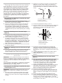
Attach Mounting Plate to Wall
NOTE: Secure the mounting plate to the wall at both end holes
drilled into the wall studs and/or drywall using either
3/16-24 x 3" round-head bolts and toggle nuts or
1/4 x 2" lag screws.
Refer to illustrations in “Possible Wall Stud Con gurations” in the
“Locate Wall Stud(s)” section.
No Wall Studs at End Holes (Figures 1 and 2)
NOTE: The mounting plate must be secured to the wall on at
least one wall stud as well as at both ends.
1. With the support tabs of the mounting plate facing forward,
insert 3/16-24 x 3" round-head bolts through both end holes
of mounting plate.
2. Start toggle nuts on bolts from the back of the mounting
plate. Leave enough space for the toggle nuts to go through
the wall and to open.
3. Position mounting plate on the wall.
4. Push the two bolts with toggle nuts through the drywall, and
nger tighten the bolts to make sure toggle nuts have
opened against drywall.
5. Insert lag screw(s) into the hole(s) drilled into wall stud(s) in
Step 2 of “Installation for No Wall Studs at End Holes” in the
“Drill Holes in Rear Wall” section.
6. Check alignment of mounting plate, making sure it is level.
7. Securely tighten all lag screws and bolts.
Wall Stud at One End Hole (Figure 3)
1. With the support tabs of the mounting plate facing forward,
insert a 3/16-24 x 3" round-head bolt through the end
hole that ts over the 5/8" (1.6 cm) hole drilled in Step 3 of
“Installation for Wall Stud at One End Hole” in the “Drill Holes
in Rear Wall” section.
2. Start a toggle nut on the bolt from the back of the mounting
plate. Leave enough space for the toggle nut to go through
the wall and to open.
3. Position mounting plate on the wall.
4. Push the bolt with toggle nut through the drywall, and nger
tighten the bolt to make sure toggle nut has opened against
drywall.
5. Insert a lag screw into the remaining end hole.
6. If installing on a second wall stud, insert a lag screw into the
other hole drilled in Step 2 of “Installation for Wall Stud at
One End Hole” in the “Drill Holes in Rear Wall” section.
7. Check alignment of mounting plate, making sure it is level.
8. Securely tighten the lag screw(s) and bolt.
Wall Studs at Both End Holes (Figure 4)
1. Position mounting plate on the wall.
2. Insert lag screws into both end holes.
3. Check alignment of mounting plate, making sure it is level.
4. Securely tighten the lag screws.
C
A
B
A. 3/16-24 x 3" round-head bolt
B. Mounting plate
C. Spring toggle nut
A. 3/16-24 x 3" round-head bolt
B. Mounting plate
C. Spring toggle nut
D. Drywall
A
B
C
D

11
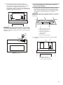
Prepare Upper Cabinet
1. Disconnect power to outlet.
2. Remove all contents from upper cabinet.
3. Place cardboard template against the bottom of the upper
cabinet, make sure the template centerline aligns with the
vertical centerline on the rear wall.
The “rear wall” arrows must be against the rear wall so that
the holes cut into the upper cabinet align with the holes in
the top of the microwave oven.
NOTE:
■If the wall behind the microwave oven (as installed) has a
partial wall covering (for example, tile backsplash), be sure
the “Rear Wall” arrows align to the thickest part of the rear
wall (for example, the thickness of the tiles rather than the
drywall).
4. Make sure the 10" (25.4 cm) dimension from the rear wall to
points “D” and “E” on the template is maintained.
5. Cut the 11⁄2" (3.8 cm) diameter hole at the circular shaded
area “G” on the template. This hole is for the power supply
cord.
NOTE: If upper cabinet is metal, the supply cord bushing
needs to be installed around the supply cord hole as shown.
6. Drill 3/8" (1 cm) holes at points “D” and “E” on the template.
These are for two 1/4-20 x 3" bolts and washers used to
secure the microwave oven to the upper cabinet.
For Roof Venting Installation Only:
7. Cut 3/4" (1.9 cm) hole at one corner of the shaded
rectangular area “F” on Cardboard Template.
8. Using a keyhole saw, cut out the rectangular area.
Install Damper Assembly
(for wall venting only)
1. Check that damper blade moves freely and opens fully.
2. Position the damper assembly on the back of the microwave
oven so that the damper blade hinge is at the top, and the
damper blade opens away from the microwave oven.
3. Secure damper assembly with two #6 x 3/8" sheet metal
screws.
D
E
G
F
10"
(25.4 cm)
10"
(25.4 cm)
Rear Wall
A
B
A. Metal cabinet
B. Power supply cord bushing
A. Back of microwave oven
B. Damper assembly
C. Damper blade
D. #6 x 3/8" Sheet metal screws
A B C D

12
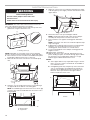
Install the Microwave Oven
IMPORTANT: The control side of the microwave oven is the
heavy side. Handle the microwave oven gently.
1. Remove the two packing spacers from the top of the vent
grille before using the microwave oven.
NOTE: Depending on your model, it may not have packing
spacers. If it does not have packing spacers, begin with step 2.
2. Place a washer on each 1/4-20 x 3" at-head bolt and place
inside upper cabinet near the 3/8" (1 cm) holes.
3. Make sure the microwave oven door is closed and taped
shut.
4. Using two or more people, lift microwave oven and hang it
on support tabs at the bottom of mounting plate.
NOTE: To avoid damage to the microwave oven, do not grip
or use the door or door handle while the microwave oven is
being handled.
5. With front of microwave oven still tilted, thread power supply
cord through the power supply cord hole in the bottom of the
upper cabinet.
6. Rotate microwave oven up toward upper cabinet.
NOTE: If venting through the wall, make sure the damper
assembly ts easily into the vent in the wall cutout.
7. Push microwave oven against mounting plate and hold in
place.
NOTE: If microwave oven does not need to be adjusted, skip
steps 7 through 9.
8. If adjustment is required, rotate microwave oven downward.
Using two or more people, lift microwave oven off of
mounting plate, and set aside on a covered surface.
9. Loosen mounting plate screws. Adjust mounting plate and
retighten screws.
10. Repeat steps 3 through 6.
11. With the microwave oven centered, and with at least one
person holding it in place, insert bolts through upper cabinet
into microwave oven. Tighten bolts until there is no gap
between upper cabinet and microwave oven.
NOTES:
■Some upper cabinets may require bolts longer or shorter
than 3" (7.6 cm). Longer or shorter bolts are available at
most hardware stores.
■Overtightening bolts may warp the top of the microwave
oven. To avoid warping, wood ller blocks (installer to
provide) may be added. The blocks must be the same
thickness as the space between the upper cabinet
bottom and the microwave oven.
WARNING
Excessive Weight Hazard
Use two or more people to move and install
microwave oven.
Failure to do so can result in back or other injury.
A
A
B
A. Mounting plate
B. Support tabs
A
A. Packing spacers (2)
A. Bolts

13
NOTE: Avoid damage to the mounting nut, screw the bolts into
the mounting nut holes around 15-20 mm by hand rst, make
sure the bolts thread in properly. Then tighten with tools.
For Roof Venting Installation Only
1. Insert damper assembly through the cabinet cutout so that
the long tab of the damper assembly slides under the raised
tabs of the damper plate. Then secure with #6 x 3/8" sheet
metal screw.
NOTE: The screw cannot be installed if the damper assembly is
not positioned as shown.
2. Connect vent to damper assembly.
Complete Installation
1. Install lters. Refer to the User Instructions for lter
placement.
2. Plug microwave oven into grounded 3 prong outlet.
3. Reconnect power.
4. Check the operation of microwave oven by placing 1 cup
(250mL) of water on the turntable and programming a cook
time of 1 minute at 100% power. Test vent fan and exhaust
by operating the vent fan.
5. If the microwave oven does not operate:
■Check that a household fuse has not blown, or that a
circuit breaker has not tripped. Replace the fuse or reset
the circuit breaker. If the problem continues, call an
electrician.
■Check that the power supply cord is plugged into a
grounded 3 prong outlet.
■See the User Instructions for troubleshooting information.
The installation is now complete.
Save Installation Instructions for future use.
A. Raised tabs
B. Damper assembly
C. #6 x 3/8" Sheet metal screw
D. Upper cabinet cutout
E. Long tab
F. Damper plate
AB C
DE F
A. Vent
B. Damper assembly (under vent)
AB
Electrical Shock Hazard
Plug into a grounded 3 prong outlet.
Do not remove ground prong.
Do not use an adapter.
Do not use an extension cord.
Failure to follow these instructions can result in death,
fire, or electrical shock.
WARNING
A. Bolt
B. Mounting Nut
15-20 mm
A
B

14
VENTING DESIGN SPECIFICATIONS
This section is intended for architectural designer and builder/
contractor reference only.
NOTES:
■Vent materials needed for installation are not provided
with microwave hood combination.
■We do not recommend using a exible metal vent.
■To avoid possible product damage, be sure to vent air
outside, unless using recirculation installation. Do not
vent exhaust air into concealed spaces, such as spaces
within walls or ceilings, attics, crawl spaces or garages.
For optimal venting installation, we recommend:
■Using roof or wall caps that have backdraft dampers.
■Using a rigid metal vent.
■Using the most direct route by minimizing the length
of the vent and number of elbows to provide ef cient
performance.
■Using uniformly sized vents.
■Using duct tape to seal all joints in the vent system.
■Using caulking compound to seal exterior wall or roof
opening around cap.
■Not installing two elbows together, for optimal hood
performance.
If venting through the wall, be sure that there is proper clearance
within the wall for the damper to open fully.
If venting through the roof, and rectangular-to-round transition is
used, be sure there are at least 3" (7.6 cm) of clearance between
the top of the microwave oven and the transition piece. See
“Rectangular-to-Round Transition” illustration.
Rectangular-to-Round Transition
NOTE: The minimum 3" (7.6 cm) clearance must exist between
the top of the microwave oven and the rectangular-to-round
transition piece so that the damper can open freely and fully.
Recommended Standard Fittings
The following length equivalents are for use when guring vent
length. See the examples in “Recommended Vent Length.”
Roof venting Roof cap
A
B
C
E
F
D
3" (7.6 cm)
A. Roof cap
B. 6" (15.2 cm) minimum diameter round vent
C. Elbow (for wall venting only)
D. Wall cap
E. 31⁄4" x 10" to 6" (8.3 x 25.4 cm to 15.2cm)
rectangular-to-round transition piece
F. Vent extension piece, at least 3" (7.6 cm) high
AB C
DE FG
A. Rectangular-to-round transition piece: 31⁄4" x 10" to 6" = 5ft
(8.3 x 25.4 cm to 15.2 cm = 1.5 m)
B. Roof cap: 31⁄4" x 10" = 24 ft (8.3 x 25.4 cm = 7.3 m)
C. 90° elbow: 31⁄4" x 10" = 25 ft (8.3 x 25.4 cm = 7.6 m)
D. 90° elbow: 6" = 10 ft (15.2 cm = 3 m)
E. Wall cap: 31⁄4" x 10" = 40 ft (8.3 x 25.4 cm = 12.2 m)
F. 45° elbow: 6" = 5 ft (15.2 cm = 1.5 m)
G. 90° at elbow: 31⁄4" x 10" = 10 ft (8.3 x 25.4 cm = 3 m)
Wall venting Wall cap

15
Recommended Vent Length
A 31⁄4" x 10" (8.3 x 25.4 cm) rectangular or 6" (15.2 cm) round
vent should be used.
The total length of the vent system including straight vent,
elbow(s), transitions and wall or roof caps must not exceed
the equivalent of 140 ft (42.7 m) for either type of vent. See
the “Recommended Standard Fittings” section for equivalent
lengths.
For best performance, use no more than three 90° elbows.
To calculate the length of the system you need, add the
equivalent lengths of each vent piece used in the system.
See the following examples:
31⁄4" x 10" (8.3 x 25.4 cm) vent system = 73 ft (22.2 m)
total
6" (15.2 cm) vent system = 73 ft (22.2 m) total
If the existing vent is round, a rectangular to round transition
piece must be used. In addition, a rectangular 3" (7.6 cm)
extension vent between the damper assembly and rectangular to
round transition piece must be installed to keep the damper from
sticking.
ASSISTANCE
Call your authorized dealer or service center. When you call, you
will need the microwave oven model number and serial number.
Both numbers can be found on the model and serial number
plate, which is located behind the microwave oven door on the
front frame of the microwave oven.
If you need additional assistance, call us at our toll-free number
or visit our website listed in the User Guide.
Replacement Parts
If any of the installation hardware needs to be replaced, call us at
our toll-free number listed in the User Guide.
Following is a list of available replacement parts. You will need
your model and serial numbers located on the front facing of the
microwave oven opening, behind the door.
■Damper Assembly
■Mounting Plate
■Upper Cabinet Template
■Mounting Screw Kit (includes parts A-G in “Parts
Supplied” in the “Tools and Parts” section)
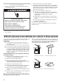
Accessories
Filler Panel Kits are available from your dealer to use when
installing this microwave oven in a 36" (91.4 cm) or
42"(106.7cm) wide opening. The ller panels come in pairs.
Each panel is 3" (7.6 cm) wide.
Filler Panel Kits: 8171336 White
8171337 Black
8171338 Biscuit
8171339 Stainless Steel
99403 Almond
See your authorized dealer or service center for details.
A B
C
6 ft (1.8 m)
2 ft
(0.6 m)
A. One 31⁄4" x 10" (8.3 x 25.4 cm) 90° elbow = 25 ft (7.6 m)
B. One wall cap = 40 ft (12.2 m)
C. 2 ft (0.6 m) + 6 ft (1.8 m) straight = 8 ft (2.4 m)
A B
C D
6 ft (1.8 m)
2 ft
(0.6 m)
A. Two 90° elbows = 20 ft (6.1 m)
B. One wall cap = 40 ft (12.2 m)
C. One rectangular-to-round transition piece = 5 ft (1.5 m)
D. 2 ft (0.6 m) + 6 ft (1.8 m) straight = 8 ft (2.4 m)
A
A. Filler panels

16
SÉCURITÉ DE L’ENSEMBLE FOUR À MICRO-ONDES/HOTTE
EXIGENCES D’INSTALLATION
Outillage et pièces
Outillage nécessaire
Rassembler les outils et pièces nécessaires avant de
commencer l’installation. Lire et suivre les instructions fournies
avec les outils mentionnés ici.
■Mètre ruban
■Crayon
■Ruban de masquage ou
■Ciseaux
■Tournevis Phillips n° 2
■Tournevis Phillips n° 3 pour vis de 1/4-20 x 3 po (7,6 cm)
■Perceuse
■Mèches de 3/16 po (5 mm), 3/8 po (1 cm) et 5/8 po (1,6 cm)
■Scie-cloche de 3/4 po (1,9 cm)
■Pince à coupe diagonale
■Détecteur magnétique (des poteaux de colombage)
■Clé à douille de 7⁄16 po (11,11 mm) (ou clé polygonale) pour
vis d’ancrage de 1/4 po x 2 po (6,4 mm x 5,1 cm)
■Foret de 1 1/2 po (3,8 cm) de diamètre pour placard de bois
ou métallique
■Scie à guichet
■Pistolet à calfeutrage et composé de calfeutrage résistant
aux intempéries
■Ruban adhésif pour conduit
Pièces fournies
Pour la commande de pièces, voir la section « Pièces de
rechange ».
REMARQUE: Les articles de quincaillerie présentés ci-dessous
sont destinés à l’utilisation sur un colombage de bois. En
présence d’une structure de mur différente, utiliser les organes
de xation app opriés.
A. Vis à tête ronde de 3/16-24 x 3 po (2)
B. Vis à tête plate de 1/4-20 x 3 po (2)
C. Rondelles (2)
D. Écrous articulés de 3/16 po (2)
E. Vis d’ancrage de 1/4 po x 2 po (2)
F. Vis à tôle de 6 x 3/8 po (2)
G. Garniture pour trou de passage du
cordon d’alimentation (1)
H. Module de clapet anti-re ux
(pour décharge à travers le mur ou
le toit)
Composants non illustrés :
■Plaque de montage
( xation à l’arriè e du four
à microondes)
■Gabarit de carton
(partie de l’emballage)
■Filtres à graisse en
aluminium
■Filtres à charbon (selon
le modèle, les lt es à
charbon peuvent ne
pas être inclus. Voir les
Instructions d’utilisation.)
REMARQUE: Selon le modèle de l’appareil, le lt e à graisse en
aluminium et le lt e à charbon peuvent être combinés.
Matériaux nécessaires
Composants standard pour décharge à travers le mur ou à
travers le toit. Voir la section « Spéci cations/conception d
circuit d’évacuation ».
A BCDEF
G
H

17
Gabarit en carton séparé
Le gabarit mural et le gabarit de l’armoire supérieure sont
intégrés dans le côté arrière de la boîte en carton. Ils sont utilisés
comme gabarit pour le mur arrière et gabarit pour l’armoire
supérieure. Découper le long des trous perforés pour détacher le
gabarit du reste de l’emballage de carton.
1. Couper le long de la ligne pointillée pour séparer le gabarit
en carton du côté arrière de la boîte en carton.
2. Placer le gabarit en carton de côté et se référer à celui-
ci au moment de l’installation lorsqu’il faut « Mark Rear
Wall» (marquer le mur arrière) et « Prepare Upper Cabinet »
(préparer l’armoire supérieure).
Exigences d’emplacement
Inspecter l’espace où le four à micro-ondes sera installé.
L’emplacement d’installation doit disposer de :
■Dimensions minimales à respecter lors de l’installation. Voir
l’ illustration « Dimensions à respecter lors de l’installation ».
■Au moins un poteau de colombage en bois 2 po x 4 po
(5,1 x 10,2 cm), et parement de plâtre ou panneau de gypse
d’épaisseur 3/8 po (1 cm) ou plus, dans l’ouverture du
placard.
■Capacité de support de charge de 150 lbs (68 kg), ceci
incluant le four à micro-ondes et les articles placés à
l’intérieur du four à micro-ondes et du placard supérieur.
■Prise de courant électrique reliée à la terre à l’intérieur
du placard supérieur. Voir la section « Spéci cations
électriques».
REMARQUES :
■Dans le cas de l’installation du four à micro-ondes à
proximité d’une paroi latérale sur le côté gauche, veiller à
laisser un espace libre de 6 po (15,2 cm) ou plus entre le
mur et le four à micro-ondes, pour permettre la manoeuvre
d’ouverture complète de la porte.
■Certains modèles sontmunisd’unepoignéedissimulée. Dans
le cas de l’installation du four à micro-ondes près d’une
paroi latérale sur le côté droit, laisser un espace libre de 3po
(7,6cm) ou plus entre le mur et le four à micro-ondes pour
permettre d’agripper la poignée intégrée à la porte.
■Les matériaux de certains placards et certains matériaux de
construction ne sont pas conçus pour résister à la chaleur
émise par le four à micro-ondes lors des opérations de
cuisson. Consulter le constructeur de la maison ou
le fabricant des placards pour déterminer si les matériaux
utilisés pourraient subir un changement de couleur,
une déstrati cation ou d’aut es dommages.
Exigences spéciales
Pour une installation avec décharge murale seulement:
■L’ouverture découpée doit être exempte d’obstruction pour
l’ajustement adéquat du conduit, et pour que le clapet
antire ux puisse manoeuv er complètement et librement.
Pour une installation avec décharge à l’extérieur à travers le
toit seulement:
■Si l’on utilise un raccord de transition rectangulaire/rond, on
doit disposer d’un espace libre de 3 po (7,6 cm) au-dessus
du four à micro-ondes pour que la lame du clapet anti-
re ux puisse manoeuver complètement et librement. Voir
l’illustration « Raccord de transition rectangulaire/rond » à
la section « Spéci cations/conception du ci cuit
d’évacuation».
Dimensions à respecter lors de l’installation
REMARQUE : La prise de courant à 3 alvéoles reliée à la terre
doit être située à l’intérieur du placard supérieur. Voir la section
«Spéci cations électriques ».
*30 po (76,2 cm) est typique pour une hauteur d’installation de
66 po (167,6 cm). Les dimensions exactes peuvent varier en
fonction du type de cuisinière/table de cuisson se trouvant en-
dessous.
REMARQUE : Pour garantir de bons résultats, ne pas obstruer
l’ouverture d’évacuation supérieure. Si la profondeur des
armoires est de plus de 14 po (35,6 cm), mais pas plus de
15po (38,1 cm), utiliser l’ensemble de montage de bourrelet
pour remplacer la plaque de montage sur le mur. L’ensemble de
montage de bourrelet (numéro de pièce W11185746) n’est pas
fourni, mais peut être acheté de Whirlpool.
A. Poteau du colombage mural de 2 po x 4 po
B. Prise à 3 alvéoles reliée à la terre
12 po (30,5 cm) minimum
14 po (35,6 cm) maximum
30 po
(76,2 cm)
minimum
AB
30 po
(76,2 cm)
typique*
66 po (167,6 cm) minimum
profondeur du
placard supérieur et
du placard latéral
12 po
≤ PLUS
PROFOND ≤ 14 po
14 po
≤ PLUS
PROFOND ≤ 15 po
Support de montage
de bourrelet
12 1/2" (31,8 cm)
6 1/4" (15,9 cm)
5 3/4"
(14,6 cm)
4 3/4
"
(12,1 cm)
10"
(25,4 cm)
12 1/2" (31,8 cm) 7 1/2" (19,1 cm)
6 3/8" (16,2 cm)
15 5/8
"
(39,71 cm)
15 5/8"
(39,71 cm)
14 1/6" (35.96 cm) 14 1/6" (35.96 cm)
G
DE
AB
F
12 1/2
"
(31,8 cm)
6 1/4
"
(15,9 cm)
5 3/4
"
(14,6 cm)
4 3/4
"
(12,1 cm)
10
"
(25,4 cm)
12 1/2
"
(31,8 cm)
7 1/2
"
(19,1 cm)
6 3/8
"
(16,2 cm)
15 5/8
"
(39,71 cm)
15 5/8
"
(39,71 cm)
14 1/6
"
(35.96 cm)
14 1/6
"
(35.96 cm)
G
D
D
E
A
B
F
B
A
A. Côté arrière de la boîte en carton.
B. Gabarit en carton (y compris le gabarit pour mur arrière et le gabarit
pour l’armoire supérieure).

18
Dimensions du produit
*La profondeur totale du produit varie légèrement selon la conception de la porte.
Spéci cations électriques
Observer les dispositions de tous les codes et règlements en
vigueur.
Nécessaire :
■Une alimentation électrique de 120 V, 60 Hz, CA
seulement, 15 ou 20 A, protégée par un fusible
ou un disjoncteur.
Recommandé :
■Un fusible temporisé ou un disjoncteur temporisé.
■Un circuit distinct exclusif à ce four à micro-ondes.
cm)
29
⁷⁄₈
po (76,0
16
¹⁄₄
po
(41,3 cm)
J
17 po
usqu'à
(43,2 cm)*
17
¹⁄₈
po
(43,5 cm)
+/-
3/16
po
(0,5 cm)
INSTRUCTIONS DE LIAISON
À LA TERRE
CONSERVEZ CES
INSTRUCTIONS
■ Pour tout appareil ménager connecté par un cordon
de courant électrique :
Il faut que le four à micro-ondes soit relié à la terre. En
cas de court-circuit électrique, la liaison à la terre réduit le
risque de choc électrique car le courant électrique
dispose d’un itinéraire direct d’acheminement à la terre.
Le four à micro-ondes est doté d’un cordon de courant
électrique qui comporte un fil de liaison à la terre, avec
broche de liaison à la terre. On doit brancher la fiche sur
une prise de courant convenablement installée et reliée à
la terre.
AVERTISSEMENT : L’utilisation incorrecte du
dispositif de liaison à la terre peut susciter un risque de choc
électrique. L’utilisateur qui ne comprend pas bien les
instructions de liaison à la terre, ou qui n’est pas certain que
le four à micro-ondes soit convenablement relié à la terre,
devrait consulter un électricien ou un technicien qualifié.
Ne pas utiliser un câble de rallonge. Si le cordon de
courant électrique est trop court, demander à un électricien
ou un technicien qualifié d’installer une prise de courant à
proximité du four à micro-ondes.
AVERTISSEMENT
Risque de choc électrique
Brancher sur une prise à 3 alvéoles reliée à la terre.
Ne pas enlever la broche de liaison à la terre.
Ne pas utiliser un adaptateur.
Ne pas utiliser un câble de rallonge.
Le non-respect de ces instructions peut causer
un décès, un incendie ou un choc électrique.

19
INSTRUCTIONS D’INSTALLATION
Dépose de la plaque de montage
Selon votre modèle, la plaque de montage peut se trouver soit
dans l’emballage en mousse, soit xée à l’arrièe du four à
micro-ondes.
REMARQUE : Couvrir la surface de travail pour éviter de
l’endommager.
1. Retirer de la cavité du four à micro-ondes tous les articles
qui peuvent s’y trouver.
2. Si la plaque de montage est xée sur la partie arrièe du four
à micro-ondes, la retirer et la mettre de côté.
3. Utiliser du ruban adhésif pour immobiliser la porte fermée du
four à micro-ondes a n qu’elle ne puisse pas s’ouvrir duran
la manipulation du four.
REMARQUE : Pour éviter d’endommager le four à micro-ondes,
ne pas prendre prise sur la porte ou la poignée de la porte
durant la manipulation du four à micro-ondes.
Réorientation du moteur du ventilateur
Le four à micro-ondes a été con guré à l’usine pou une
installation avec recyclage de l’air. Pour la décharge de l’air
aspiré à travers le mur ou à travers le toit, on doit modi er le
système de ventilation du fou.
REMARQUE : Si le produit est destiné à être utilisé avec
recyclage de l’air, ne pas tenir compte de cette section.
Conserver le module du clapet pour le cas où une autre méthode
d’évacuation serait utilisée ultérieurement ou dans le cas où le
four à micro-ondes serait réinstallé ultérieurement en un autre
endroit, avec décharge à l’extérieur à travers le mur ou à travers
le toit.
Pour une installation avec décharge murale
seulement
1. Ôter les vis xant la plaque de support du clapet à la partie
arrière du four à micro-ondes et les garder pour plus tard.
2. Tourner et maintenir la plaque de support du clapet à la
verticale, comme illustré.
3. Retirer deux vis de ventilateur xant le moteur du ventilateur
au four à micro-ondes et les garder pour plus tard.
4. Débrancher le l du moteur de ventilateur du connecteur.
5. Sortir le moteur du four à micro-ondes et le garder pour plus
tard.
A
B
A. Plaque de support du clapet anti-re ux
B. Vis
A. Plaque de support du clapet
A
A. Vis du ventilateur (dans des trous encastrés)
A
A
B
A. Fil du moteur de ventilateur
B. Connecteur
A
A. Moteur du ventilateur

20
6. Utiliser une pince coupante pour découper doucement les
points de xation rectangulaires des couvercles de
fermeture.
7. Tenir le l du moteur, placer le l à travers le pont du moteur
de ventilateur.
8. Abaisser le moteur de ventilateur pour le réinsérer dans le
four à micro-ondes. L’ori ce de sortie fait face vers l’arrière
du four à micro-ondes.
9. Rebrancher le l du moteur de ventilateur dans le
connecteur.
10. Fixer de nouveau les deux vis du ventilateur dans les trous
encastrés situés à l’arrière du four à micro-ondes.
11. S’assurer que les deux vis sont bien xées dans les trous de
vis du moteur de ventilateur pour que le moteur ne puisse
pas bouger.
12. Remettre la plaque de support du clapet à sa position
horizontale d’origine.
B
A
A. Pince coupante diagonale
B. Couvercles de fermeture rectangulaire du clapet
A. Pont du moteur de ventilateur
B. Fil du moteur de ventilateur
A
B
A. Ori ce de sortie
A
A
B
A. Fil du moteur de ventilateur
B. Connecteur
A. Vis
B. Trous encastrés
A B
AB
A. Vis
B. Trous de vis du moteur de ventilateur
A. Plaque de support du clapet
A
La page est en cours de chargement...
La page est en cours de chargement...
La page est en cours de chargement...
La page est en cours de chargement...
La page est en cours de chargement...
La page est en cours de chargement...
La page est en cours de chargement...
La page est en cours de chargement...
La page est en cours de chargement...
La page est en cours de chargement...
La page est en cours de chargement...
La page est en cours de chargement...
-
 1
1
-
 2
2
-
 3
3
-
 4
4
-
 5
5
-
 6
6
-
 7
7
-
 8
8
-
 9
9
-
 10
10
-
 11
11
-
 12
12
-
 13
13
-
 14
14
-
 15
15
-
 16
16
-
 17
17
-
 18
18
-
 19
19
-
 20
20
-
 21
21
-
 22
22
-
 23
23
-
 24
24
-
 25
25
-
 26
26
-
 27
27
-
 28
28
-
 29
29
-
 30
30
-
 31
31
-
 32
32


KitchenAid W11496339A Manuel utilisateur
- Catégorie
- Fours
- Taper
- Manuel utilisateur
dans d''autres langues
- English: KitchenAid W11496339A User manual
Documents connexes
Autres documents
-
IKEA IMH15XVQ5 Guide d'installation
-
Jenn-Air YJMV9196CS0 Guide d'installation
-
Maytag YMMV4205DW0 Installaion Instructions
-
-
IKEA YWMH1162XVS1 Guide d'installation
-
Whirlpool W11595046A Microwave Oven Hood Combination Le manuel du propriétaire
-
IKEA IMH172DS1 Guide d'installation
-