
Instruction
047U59158
07/2023
Giacomini S.p.A.
Via per Alzo 39, 28017 San Maurizio d’Opaglio (NO) Italia
+39 0322 923372 - giacomini.com
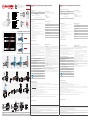
CONFIGURATION CURVE Kv
Ingresso diritto
In-line pipes
Durchgang
B B
A A
12 2 3
A
145
3,4
Ingresso a squadra
90°-angled pipes
Eck
B B
A A
12 2 3
A
145
4,5
0,1 1,0 10,0
Q [m3/h]
0,01
0,10
1,00
∆p [bar]
4,53,4
(g.1)
1 2 3
5 mm
5 mm
OFF
4 5 6
5 mm
5 mm
OFF
(g.5)
(g.3A)
B B
A
A
12
2 3
A
145
B B
A A
12
2
3
A
1
45
B B
A
A
12 2
3
A
1
45
(g.3B) (g.3C)
12
6
7
8
3
4
5
(g.2)
CODE AB [mm] C [mm] D [mm] E [mm] F [mm] G H I [mm] B+I [mm]
R145XC004 G 3/4”M 85 40 45 133 70 G 3/4”F G 3/4”F 33 118
I
A
E
A F
H
G
H
A
F
B
DC
I
A
E
A F
H
G
H
A
F
B
DC
I
A
E
A F
H
G
H
A
F
B
DC
(g.6)
(g.4)
VIDEO
TUTORIAL
(IT)
VIDEO
TUTORIAL
(EN)
R145XC
(g.3A)
Versioni e codici
CODICE ATTACCHI
R145XC004
Corpo principale:
- lato caldaia: G 3/4”M
- lato ritorno impianto: G 3/4”M
Raccordo a bocchettone: G 3/4”F x G 3/4”F
Componenti inclusi
• Tappo G 3/4”F per raccordo ingresso/uscita
• Raccordo a bocchettone G 3/4”F x G 3/4”F
Ricambi
• P1 45 XCY001: magnete
• P145XCY002: ltro
Versions and product codes
PRODUCT CODE CONNECTIONS
R145XC004
Main body:
- boiler circuit: G 3/4”M
- system return circuit: G 3/4”M
Tail piece: G 3/4”F x G 3/4”F
Components included
• G3/4”Fcapforinlet-outlettting
• G3/4”FxG3/4”Ftailpiece
Spare parts
• P145XCY001: neodymium magnet
• P1 45 XCY002:stainlesssteellter
Avvertenze per la sicurezza. L’installazione, la messa in ser vizio e la periodica manutenzione del prodotto devono essere eseguite da personale professionalmente abilitato,
in accordo con i regolamenti nazionali e/o i requisiti locali. L’installatore qualicato deve adottare tutti gli accorgimenti necessari, incluso l’utilizzo di Dispositivi di Protezione
Individuale, per assicurare la propria incolumità e quella di terzi. L’errata installazione può causare danni a persone, animali o cose nei confronti dei quali Giacomini S.p.A. non
può essere considerata responsabile.
Smaltimento imballo. Scatole in cartone: raccolta differenziata carta. Sacchetti in plastica e pluriball: raccolta differenziata plastica.
Smaltimento del prodotto. Alla ne del suo ciclo di vita il prodotto non deve essere smaltito come riuto urbano. Può essere por tato ad un centro speciale di riciclaggio ges tito
dall’autorità locale o ad un rivenditore che offre questo servizio.
Altre informazioni. Per ulteriori informazioni consultare il sito giacomini.com o contattare il servizio tecnico. Questa comunicazione ha valore indicativo. Giacomini S.p.A. si
riserva il diritto di apportare in qualunque momento, senza preav viso, modiche per ragioni tecniche o commerciali agli articoli contenuti nella presente comunicazione. Le
informazioni contenute in questa comunicazione tecnica non esentano l’utilizzatore dal seguire scrupolosamente le normative e le norme di buona tecnica esistenti.
Safety Warning. Installation, commissioning and periodical maintenance of the product must be carried out by qualied operators in compliance with national regulations
and/or local standards. A qualied installer must take all required measures, including use of Individual Protection Devices, for his and others’ safety. An improper installation
may damage people, animals or objects towards which Giacomini S.p.A. may not be held liable.
Package Disposal. Carton boxes: paper recycling. Plastic bags and bubble wrap: plastic recycling.
Product Disposal. Do not dispose of product as municipal waste at the end of its life cycle. Dispose of product at a special recycling platform managed by local authorities
or at retailers providing this type of service.
Additional information. For more information, go to giacomini.com or contact our technical assistance service. This document provides only general indications. Giacomini
S.p.A. may change at any time, without notice and for technical or commercial reasons, the items included herewith. The information included in this technical sheet do not
exempt the user from strictly complying with the rules and good practice standards in force.
Dati tecnici
• Fluidodiimpiego:acqua,soluzioneglicolate(max.50%di
glicole)
• Campoditemperatura:5÷90°C
• Pressionemassimadiesercizio:3bar
• Filtro:800μm
• Capacitàmagneticadelmagnete:13000Gauss
Materiali
• Corpoprincipale,valvolaasferaeraccordiingresso/uscita:
ottoneCW617N-UNIEN12165cromato
• Manigliaafarfallaadunaalettainalluminioverniciatodicolore
bianco
• Cartucciaportaltro:nylon66caricatovetro20%(PA66-GF20)
• Filtro:acciaioinoxAISI304
• Valvoladiritegno:POM
• Guarnizioni:EPDM
• Magnete:neodimio(N42H)
Perdite di carico (g.1)
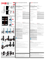
Componenti (g.2)
1Corpo del defangatore
2Valvola a sfera con maniglia bianca
3Cartuccia porta ltro
4Filtro
5Magnete
6Valvola di ritegno
7Raccordo a bocchettone
8Tappo
Technical data
• Fluid:water,glycol-basedsolution(max.50%ofglycol)
• Temperaturerange:5÷90°C
• Maxworkingpressure:3bar
• Filter:800μm
• Magneticcapacityofmagnet:13000Gauss
Materials
• Mainbody,ballvalveandinlet/outletttings:CW617N-UNI
EN12165chrome-platedbrass
• Minilevervalveinwhitevarnishedaluminum
• Filtercartridge:20%glass-lled66nylon(PA66-GF20)
• Filter:AISI304stainlesssteel
• Checkvalve:POM
• Gaskets:EPDM
• Magnet:neodymium(N42H)
Losses of pressure (g.1)
Components (g.2)
1Dirt separator body
2Ball valve with white mini lever
3Filter cartridge
4Filter
5Magnet
6Check valve
7Tail piece
8Cap
Funzionamento (g.3A, 3B, 3C)
Il usso d’acqua entra nel ltro-defangatore dall’ingresso
prescelto (sull’ingresso non utilizzato è necessario posizionare
il tappo in dotazione) e passa attraverso un ltro che favorisce
laseparazionedelleparticelle;èinoltre presente un magnete in
gradoditrattenereleimpuritàmetalliche.
Illtro èdotatodiuna valvola di intercettazioneasfera e diuna
valvola di ritegno che permettono di isolarlo completamente
dalrestodell’impiantoedeseguirele operazionidipuliziasenza
doversvuotarel’impianto.
Ruotando la maniglia la valvola a sfera va in posizione di
manutenzione, interrompendo l’ingresso dell’acqua all’interno
deldispositivo.
g.3A Funzionamento con usso in linea
g.3B Funzionamento con usso a squadra
g.3C Flusso intercettato
AIngresso uido
BUscita uido
1Tappo su ingresso non utilizzato
2Maniglia in posizione di normale funzionamento
3Maniglia in posizione di manutenzione
4Sfera in posizione di manutenzione per isolare il ltro-defangatore
5Valvola di non ritorno per evitare lo svuotamento della caldaia
Fluido in ingresso nel ltro-defangatore, carico di impurità
Fluido in uscita dal ltro-defangatore, privo di impurità
Installazione (g.4)
AVVERTENZA. Prima di installare il ltro si consiglia di vericare le condizioni
operative dell’impianto, come pressione e temperatura, per garantire che siano
comprese entro il campo di funzionamento. È importante che l’accesso al ltro sia
libero per eventuali manutenzioni.
Il ltro-defangatore deve essere installato sul circuito di ritorno
dell’impianto di riscaldamento per proteggere la caldaia dalle
impuritàpresentinelletubazioni.
Grazieallesuedimensionicompatteèpossibileinstallarloappena
sottounacaldaiamurale.
Primadiprocedereallamessainservizio è necessario chiudere
l’ingressononutilizzatodelltro-defangatoreutilizzandoiltappo
indotazione.
All’interno della confezione è inoltre presente un raccordo a
bocchettone G 3/4”F che può essere utilizzato per connettere
l’uscitadelltrodirettamenteallacaldaiamurale.
Illtro-defangatorepuòesseremontatoin qualunqueposizione,
adeccezionedell’installazioneconcartucciarivoltaversol’alto.
AVVERTENZA. Il ltro-defangatore è dotato di un magnete che provoca campi
magnetici , eventuale causa di danni ad apparecchiature elettroniche (compresi
pacemaker ) che siano poste in prossimità.
Utilizzo del ltro-defangatore come un normale ltro per
impianti di riscaldamento/rarescamento
In caso di funzionamento del dispositivo con usso lineare
(vedere paragrafo “Funzionamento”), esso svolge la funzione di
unnormaleltroperimpiantidiriscaldamento/rarescamento.
Operation (g.3A, 3B, 3C)
The water ow entersthe lter-dirtseparator from theselected
inlet (the unused inlet must be closed with the cap included)
andthenthroughalterthatenhancestheparticleseparation;a
magnetisalsoprovidedtoretainmetalimpurities.
The lter includes a shut-o ball valve and a check valve that
enable toisolate it completely fromtherest of thecomponents
andcleanitwithoutdrainingthesystem.
By turningthe handle, theballvalve goes into the maintenance
position,preventingthewaterfromenteringthedevice.
g.3A Operation with in-line ow
g.3B Operation with 90°-angled ow
g.3C Shut-o ow
AFluid inlet
BFluid outlet
1Cap on not used inlet
2Handle in normal operation position
3Handle in maintenance position
4Ball in maintenance position to insulate the lter-dirt separator
5Non-return valve to prevent the boiler emptying
Fluid lled with impurities entering the lter-dirt separator
Fluid released from the lter-dirt separator with no impurities
Installation (g.4)
WARNING. Before installing the lter, check the system working conditions, such
as pressure and temperature, to make sure they are within the working range. Access
to the lter must be free to perform maintenance.
Thelter-dirtseparatorshouldbeinstalledontheheatingreturn
circuittoprotecttheboilerfromtheimpuritiesinsidethepipes.
Its compact dimensions makes it t for installation right under
wall-mountboilers.
Before starting up the system, the unused inlet of the lter-dirt
separatormustbeclosedwiththeincludedcap.
ThepackagealsocontainsaG3/4”Ftailpiecetoconnectthelter
outletdirectlytothewall-mountboiler.
The lter-dirt separator can be placed in any position, but the
cartridgemustneverpointupwards.
WARNING. The lter-dirt separator is provided with a magnet that generates
magnetic elds that may damage electronic devices (including pacemakers
) nearby.
Use of the lter-dirt separator as a regular lter for heating/
cooling systems
Whenusedinalinearow(see“Operation”),thedeviceworksasa
regularlterforheating/coolingsystems.
Manutenzione (g.5)
Pulizia del ltro-defangatore
Duranteilfunzionamentodell’impianto,leimpuritàsidepositanoall’internodelltro-defangatore.
La pulizia del ltro può essere eettuata senza dover svuotare l’impianto, masempre in condizioni di assenza di usso all’interno del
dispositivo (impianto spento).
Perpulireilltroerimuovereleimpuritàprocederecomesegue:
1) ad impianto spento,ruotarelamanigliadellavalvoladiintercettazioneasferaintegrataperportarlainposizionedimanutenzioneeisolare
ildispositivodalrestodell’impianto;
2)rimuovereilmagnetedalacartuccia,svitandoloinsensoantiorarioconunachiaveabrugolada5mm;leimpuritàferrosechesierano
accumulatesidepositerannoall’internodelltro-defangatore;
3)dopoaverattesoqualcheminuto,svitarelacartucciaerimuovereilltro;
4)lavareicomponentiappenarimossi(ltro,cartucciaemagnete)sottoacquacorrente;
5)rimontareicomponentipulitiall’internodeldispositivo;
6)primadirimetterel’impiantoinfunzione,ruotarelamanigliadellavalvoladiintercettazioneasferaintegrataperportarlainposizionedi
normalefunzionamento.
AVVERTENZA. Prevedere una valvola di sfogo aria nel circuito dell’impianto, per espellere l’aria accumulata dopo le fasi di manutenzione e pulizia dei componenti.
Maintenance (g.5)
Cleaning the lter-dirt separator
Impuritiescollectinsidethelter-separatorwhenthesystemisON.
Thereisnoneedtodrainthesystem,butthedevicemustbeemptytocleanthelter(systemOFF).
Tocleanthelterandremovetheimpurities,followthestepsbelow:
1) turnOFFthesystem,turnthehandleoftheshut-oballvalvetomoveittothemaintenancepositionandisolatethedevicefromthe
restofthesystem;
2) removethemagnetfromthecartridgebyrotatingitincounterclockwisedirectionwitha5-mmAllenwrench;theferrousdebriscollected
willrestinsidethelter-dirtseparator;
3) afterafewminutes,screwoutthecartridgeandremovethelter;
4)rinsethedisassembledcomponents(lter,cartridgeandmagnet)underfreshwater;
5)reassemblethecleancomponentsinsidethedevice;
6) turnthehandleoftheshut-oballvalvetomoveittothenormaloperatingposition,beforeturningthesystembackON.
WARNING. Install an air vent valve on the system circuit to release the air after servicing and cleaning the components.
R145XC Compact magnetic lter-dirt separator
EN
R145XC Filtro-defangatore magnetico compatto
IT
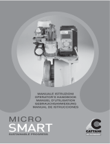
Dimensioni (g.6) Dimensions (g.6)

Instruction
047U59158
07/2023
Giacomini S.p.A.
Via per Alzo 39, 28017 San Maurizio d’Opaglio (NO) Italia
+39 0322 923372 - giacomini.com
CONFIGURATION CURVE Kv
Ingresso diritto
In-line pipes
Durchgang
B B
A A
12 2 3
A
145
3,4
Ingresso a squadra
90°-angled pipes
Eck
B B
A A
12 2 3
A
145
4,5
0,1 1,0 10,0
Q [m3/h]
0,01
0,10
1,00
∆p [bar]
4,53,4
(g.1)
1 2 3
5 mm
5 mm
OFF
4 5 6
5 mm
5 mm
OFF
(g.5)
(g.3A)
B B
A
A
12
2 3
A
145
B B
A A
12
2
3
A
1
45
B B
A
A
12 2
3
A
1
45
(g.3B) (g.3C)
12
6
7
8
3
4
5
(g.2)
CODE AB [mm] C [mm] D [mm] E [mm] F [mm] G H I [mm] B+I [mm]
R145XC004 G 3/4”M 85 40 45 133 70 G 3/4”F G 3/4”F 33 118
I
A
E
A F
H
G
H
A
F
B
DC
I
A
E
A F
H
G
H
A
F
B
DC
I
A
E
A F
H
G
H
A
F
B
DC
(g.6)
(g.4)
VIDEO
TUTORIAL
(IT)
VIDEO
TUTORIAL
(EN)
R145XC
(g.3A)
Versionen und Artikelnummern
ARTIKELNUMMER ANSCHLÜSSE
R145XC004
Messingkörper:
- Zum Wärmeerzeuger: G 3/4” AG
- Systemrücklauf: G 3/4” AG
Verschraubung: G 3/4” IG x G 3/4” IG
Im Lieferumfang des Abscheiders R145XC enthaltene Komponenten
• KappeG3/4”IGzumVerschließendesnichtgenutzenAnschlusses
• VerschraubungG3/4”IGxG3/4”IG
Ersatzteile
• P1 45 XCY001:NeodymMagnet
• P1 45 XCY002:Edelstahlsieb
Weitere Informationen erhalten Sie auf www.giacomini.de oder über unseren technischen Kundendienst. Das vorliegende Dokument enthält lediglich allgemeine Angaben.
Die Giacomini GmbH behält sich das Recht vor, unangekündigte Änderungen am vorliegenden Dokument aus technischen oder kaufmännischen Gründen vorzunehmen. Die
im vorliegenden Dokument enthaltenen Angaben entbinden den Benutzer nicht von der Picht zur strengen Einhaltung der geltenden gesetzlichen Vorschriften und Normen.
Entsorgung der Verpackung: Kartons: Papier-Recycling Kunststoffsäcke und Luftpolsterfolie: Kunststoff-Recycling.
Entsorgung des Produkts: Das Produkt darf am Ende seiner Lebensdauer nicht über den Hausmüll entsorgt werden. Mit der Entsorgung des Produkts ist ein einschlägiger
Fachbetrieb zu beauftragen.
Sicherheitshinweise Installation, Inbetriebnahme und regelmäßige Wartung des Produkts sind durch qualizierte Fachkräfte entsprechend den geltenden Gesetzen und Normen
durchzuführen. Durch das Installationspersonal sind alle erforderlichen Sicherheitsmaßnahmen einschließlich der Verwendung persönlicher Schutzausrüstung zu ergreifen. Die Giacomini
GmbH übernimmt keine Haftung für Sach- oder Personenschäden, die auf fehlerhafte Installation zurückzuführen sind.
Technische Daten
• FürWasserundWasser/Glykolgemischemitmax50%
Glykolanteil
• Temperaturbereich:5÷90°C
• MaxBetriebsdruck:3bar
• MaschenweiteFiltersieb:800μm
• MagnetischeKapazität:13.000Gauss
Materialien
• Messingkörper:CW617N-DINEN12165,verchromt
• MinigrifürKugelhahn:Aluminium,weißlackiert
• Filterkartusche:20%glasfaserverstärktesNylon66(PA66-GF20)
• Filtersieb:EdelstahlAISI304
• Rückschlagventil:POM
• Dichtungen:EPDM
• Magnet:Neodym(N42H)
Druckverlust (Abb.1)
Komponenten (Abb.2)
1Körper
2Kugelhahn mit Minigriff
3Filterkartusche
4Filtersieb
5Magnet
6Rückschlagventil
7Verschraubung
8Kappe
Funktionsweise (Abb.3A, 3B, 3C)
Die Flüssigkeit strömt durch den gewählten Einlass in
den Abscheider (der nicht benutzte Einlass muss mit der
mitgelieferten Kappe verschlossen werden) und dann
durch das Filtersieb. Der ebenfalls vorhandene Magnet hält
ferromagnetische Verunreinigungen zurück. Der Abscheider
verfügtübereinenAbsperrkugelhahnundeinRückschlagventil,
dieesermöglichenihnvollständigvondenübrigenKomponenten
in der Anlage zu isolieren und zu reinigen, ohne das System
entleerenzumüssen.DurchDrehendesGriswirdderKugelhahn
indieWartungspositiongebracht,umeinEindringenvonWasser
indenAbscheiderzuverhindern.
Abb.3A Funktionsweise im Durchgangsprinzip
Abb.3B Funktionsweise im Eckprinzip
Abb.3C Absperrfunktion
ASystemrücklauf
BZum Wärmeerzeuger
1Kappe auf nicht benutztem Einlass
2Griff in Offen-Position
3Griff in Wartungsposition Geschlossen
4Kugel in Wartungsposition um den Abscheider vom System zu trennen
5Rückschlagventil, um eine Entleerung des Wärmerzeugers zu
verhindern
Verschmutztes Wasser am Einlass
Gereinigtes Wasser am Aulass
Installation (Abb.4)
ACHTUNG. Prüfen Sie vor dem Einbau des Abscheiders die Betriebsbedingungen
der Anlage, wie Druck und Temperatur, um sicherzustellen, dass sie innerhalb des
zulässigen Betriebsbereichs liegen. Der Zugang zum Abscheider muss für die Wartung
frei sein.
DerAbscheidersollteimHeizungsrücklaufinstalliertwerden,um
denWärmeerzeugerz.B.WandthermenoderWohnungsstationen
etc.vorVerunreinigungenzuschützen.
Dank seiner kompakten Abmessungen kann der R145XC direkt
unterdemWärmeerzeugerinstalliertwerden.
VorderInbetriebnahmederAnlagemussderunbenutzteEingang
des Abscheiders mit der mitgelieferten Kappe verschlossen
werden.
Eine Verschraubung mit G3/4” IG x G3/4” IG zum direkten
Anschluss des Abscheiders an den Wärmerzeuger ist im
Lieferumfangenthalten.
Der Abscheider kann in jeder beliebigen Position angebracht
werden,dieKartuschedarfjedochniemalsnachobenzeigen.
ACHTUNG. Der Abscheider ist mit einem Magneten ausgestattet. Magnetische Felder
in der Nähe des Abscheiders sind somit beabsichtigt. Diese können sich auf magnetisch
empndliche Geräte inclusive Herzschrittmacher () negativ auswirken.
Verwendung des Abscheiders als regulärer Filter für
Heizungs- und Kühlanlagen
Bei Verwendung in geraden Rohrleitungsystemen arbeitet der
AbscheideralsregulärerFilterfürHeiz-/Kühlsysteme.
Wartung (Abb.5)
ReinigendesmagnetischenAbscheiders
WenndasSystemeingeschaltetist,sammelnsichVerunreinigungenimAbscheider.ZurWartungistesnichtnotwendigdasSystemzu
entleeren.
DerAbscheiderjedochmussleersein,umdasFiltersiebzureinigen(SystemAUS).
UmdasFiltersiebzureinigen,gehenSiewiefolgtvor:
1)SchaltenSiedieAnlageAUS,drehenSiedenGridesAbsperrkugelhahnsindieWartungsposition;
2)EntfernenSiedenMagnetenausderKartusche,indemSieihnmiteinem5-mm-InnensechskantschlüsselgegendenUhrzeigersinn
drehen;diegesammelteneisenhaltigenVerunreinigungenbleibenimInnerendesAbscheiders;
3)WartensieeinigeMinutenabbissichdieFlüssigkeitimabscheiderberuhigtunddiemagnetischenBestandteilesichabgesetzthaben.
SchraubendanndieKartuscheab,entnehmenSiedasSieb;
4)SpülenSiediedemontiertenTeile(Kartusche,SiebundMagnet)unterfrischemWasserab;
5)SetzenSiediegereinigtenTeilewiederzusammen;achtenSiedarauf,dasssiedenMagnetennurhandfestanziehen;
6)DrehenSiedenGridesAbsperrkugelhahns,umihnindienormaleBetriebspositionzub ringen,bevorSiedasSys temwiedereins chalten .
ACHTUNG. Installieren Sie ein Entlüftungsventil im Systemkreislauf, um die Anlage nach Wartung und Reinigung der Komponenten zu entlüften.
R145XC Kompakter magnetischer SchlammabscheiderDE
Abmessungen (Abb.6)
Versions et codes
CODE RACCORDEMENTS
R145XC004
Corps principal :
- Côté chaudière : G 3/4”M
- Côté retour installation : G 3/4”M
Raccord au tube : G 3/4”F x G 3/4”F
Composants inclus
• BouchonG3/4”Fpourlaraccordentrée/sortie
• Raccord au tube G 3/4”F x G 3/4”F
Accessoires
• P145XCY001 :aimantnéodyme
• P145XCY002 : ltre
Avertissements relatifs à la sécurité. L’installation, la mise en service et la maintenance périodique du produit doivent être effectuées par du personnel qualié, conformément à
la réglementation nationale et/ou aux exigences locales. L’installateur qualié doit prendre toutes les précautions
nécessaires, y compris l’utilisation d’équipements de protection individuelle, pour assurer sa propre sécurité et celle des tiers. Une installation incorrecte peut causer des blessures
aux personnes, aux animaux ou des dégâts matériels vis-à-vis desquels Giacomini S.A. ne saurait être tenue responsable.
Mise au rebut de l’emballage. Boîtes en carton : collecte sélective du papier. Sachets en plastique et lm à bulles : collecte sélective du plastique.
Mise au rebut du produit. À la n de son cycle de vie, le produit ne doit pas être éliminé avec les déchets urbains. Il peut être amené à un centre de recyclage spécial géré
par les autorités locales .
Autres informations. Pour plus d’informations, consulter le site giacomini.fr ou contacter le bureau technique. Cette communication n’est fournie qu’à titre indicatif. Giacomini S.A.
se réser ve le droit d’appor ter, à tou t moment et sans préavis, des modications pour des raisons techniques ou commerciales aux élémen t s contenus dans la présente communication.
Les informations contenues dans cette note technique ne dispensent pas l’utilisateur de respecter strictement les normes d’usage et la réglementation en vigueur.
Données techniques
• Fluidesd’application:eau,solutionglycolée(max.50%di
glicole)
• Plagedetempérature:5÷90°C
• Pressionmaximaled’exercice:3bar
• Filtre:800μm
• Capacitémagnétiquedel’aimant:13000Gauss
Matériaux
• Corpsprincipal,vanneàboisseausphériqueetraccords
entrée/sortie:laitonCW617N-UNIEN12165chromé
• Poignéepapillonenaluminiumpeintenblanc
• Cartoucheporte-ltre:nylon66chargéà20%(PA66-GF20)
• Filtre:AcierinoxAISI304
• Clapetderetenue:POM
• Joints:EPDM
• Aimant:néodyme(N42H)
Pertes de charge (g.1)
Composants (g.2)
1Corps du ltre
2Vanne à sphère avec poignée blanche
3Cartouche porte-ltre
4Filtre
5Aimant
6Clapet de retenue
7Raccord au tube
8Bouchon
Fonctionnement (g.3A, 3B, 3C)
Ledébitd’eauentredansleltremagnétiqueàpartirdel’entrée
présélectionnée(lebouchonfournidoitêtreplacésurl’entréenon
utilisée)etpasseàtravers unltrequifavorise laséparationdes
particules;onretrouveégalementunaimantenmesurederetenir
lesimpuretésmétalliques.
Leltreestéquipéd’unevanneàsphèreetd’unclapetanti-retour
qui permettent de l’isoler complètement du reste du système
et d’eectuer les opérations de nettoyage sans avoir à vider
l’installation.
Tournerlapoignéepourfermerlavanneàboisseau,interrompant
l’entréedel’eaudansledispositif.
g.3A Fonctionnement du ux en ligne
g.3B Fonctionnement du ux en angle
g.3C Blocage du ux
AEntrée uide
BSortie uide
1Bouchon sur l’entrée non utilisé
2Poignée en position d’ouverture
3Poignée en position de fermeture
4Vanne à boisseau en position fermée
5Clapet anti-retour pour empêcher la vidange de la chaudière
Fluide en entrée dans le ltre magnétique, chargé d’impuretés
Fluide en sortie du ltre magnétique, exempt d’impuretés
Installation (g.4)
AVERTISSEMENT. Avant d’installer le ltre, il est recommandé de vérier
les conditions de fonctionnement de l’installation, telles que la pression et la
température, pour s’assurer qu’elles se situent dans la plage de fonctionnement. Il
est important que l’accès au ltre soit libre pour tout entretien.
Le ltre magnétique doit être installé sur le circuit de retour
de l’installation de chauage pour protéger la chaudière des
impuretésprésentesdanslestuyaux.
Grâce à ses dimensions compactes, il est possible de l’ instal ler
justeendessousd’unechaudièremurale.
Avantdeprocéderàlamiseenservice,ilestnécessairedefermer
l’entréeinutiliséedultremagnétiqueàl’aidedubouchonfourni.
À l’intérieur de l’emballage se trouve également un raccord
G 3/4 ”F qui peut être utilisé pour connecter la sortie du ltre
directementàlachaudièremurale.
Le ltre magnétique peut être monté dans toute position, à
l’exceptiondel’installationaveclacartouchetournéeverslehaut.
AVERTISSEMENT. Le ltre magnétique est équipé d’un aimant qui génère des
champs magnétiques , susceptibles d’endommager les équipements électroniques
(y compris les pacemakers ) placés à proximité.
Utilisation du ltre magnétique comme ltre normal pour
installations de chauage/refroidissement
Encasdefonctionnementdel’appareilavecundébitlinéaire
(voirparagraphe«Fonctionnement»),ilremplitlafonctiond’un
ltrenormalpourinstallationsdechauage/refroidissement.
Entretien (g.5)
Nettoyage du ltre magnétique
Pendantlefonctionnementdel’installation,lesimpuretéssedéposentàl’intérieurdultremagnétique.Leltrepeutêtrenettoyésansavoir
àviderlesystème,maistoujoursenconditionsd’absence de débit à l’intérieur du dispositif (système éteint).
Pournettoyerleltreetéliminerlesimpuretés,procédercommesuit:
1)installationéteinte,fermerlavanneàsphèreintégréepourisolerledispositifdurestedel’installation
2)retirerl’aimantdelacartoucheenledévissantdanslesensinversedesaiguillesd’unemontreavecunecléAllende5mm;lesimpuretés
ferreusesquis’étaientaccumuléessedéposerontàl’intérieurdultremagnétique;
3)aprèsavoirattenduquelquesminutes,dévisserlacartoucheetretirerleltre;
4)laverlescomposantsàpeineretirés(ltre,cartoucheetaimant)àl’eaucourante;
5)remonterlescomposantsnettoyésàl’intérieurdudispositif;
6)avantderemettrel’installationenservice,ouvrirlavanneàboisseausphériqueintégré.L’appareilreprendralefonctionnementnormal.
AVERTISSEMENT. Prévoir une vanne de purge d’air dans le circuit de l’installation, pour expulser l’air accumulé après les phases d’entretien et de nettoyage des composants.
R145XC Filtre magnétique compactFR
Dimensions (g.6)
-
 1
1
-
 2
2


dans d''autres langues
- italiano: Giacomini R145XC Istruzioni per l'uso
- English: Giacomini R145XC Operating instructions
- Deutsch: Giacomini R145XC Bedienungsanleitung
Documents connexes
Autres documents
-
Watts DSPN Series Guide d'installation
-
Honeywell HF 49 Le manuel du propriétaire
-
Bosch vs 07g2213 hygienic power Le manuel du propriétaire
-
Bosch BX31810/05 Le manuel du propriétaire
-
Danfoss Oil Pump KS Guide d'installation
-
Baumer YTED Guide d'installation
-
Siemens VSX32500/02 Le manuel du propriétaire
-
Bosch BX31800/03 Manuel utilisateur
-
 Cattani MICRO SMART Operator's Handbook Manual
-
Rowenta RH8469 Le manuel du propriétaire
