JennAir JDSP536HL Guide d'installation
- Catégorie
- Cuisinières
- Taper
- Guide d'installation

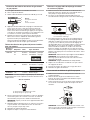
INSTALLATION INSTRUCTIONS
CommerCial-Style Dual Fuel ConveCtion rangeS
30" (76.2 Cm), 36" (91.4 Cm), anD 48" (121.9 Cm)
For residential use only
INSTRUCTIONS D’INSTALLATION
CuiSinière à Double CombuStible à ConveCtion De Style CommerCial
De 30 po (76,2 Cm), 36 po (91,4 Cm) et 48 po (121,9 Cm)
Pour utilisation résidentielle uniquement
Table of Contents/Table des matières
W11114333A www.jennair.com (U.S.A.) www.jennair.ca (Canada)
RANGE SAFETY .............................................................................2
INSTALLATION REQUIREMENTS ................................................. 4
Tools and Parts ............................................................................4
Water Filtration System Location Requirements ........................5
Water Supply Requirements ........................................................5
Location Requirements ................................................................6
Electrical Requirements: U.S.A. Only ..........................................8
Electrical Requirements: Canada Only ........................................8
Gas Supply Requirements ...........................................................8
INSTALLATION INSTRUCTIONS .................................................10
Unpack the Range .....................................................................10
Remove Door .............................................................................11
GAS CONVERSIONS ....................................................................12
Propane Gas Conversion ...........................................................12
Natural Gas Conversion .............................................................16
Install Anti-Tip Bracket ...............................................................20
Make Gas Connection ...............................................................21
Verify Anti-Tip Bracket Location ................................................21
Install Griddle Tray .....................................................................21
Electronic Ignition System .........................................................22
Level Range ................................................................................22
Install Kick Plate .........................................................................23
Complete Installation .................................................................23
SÉCURITÉ DE LA CUISINIÈRE ...................................................24
EXIGENCES D’INSTALLATION ...................................................26
Outils et pièces ...........................................................................26
Exigences d’emplacement du système de filtration d’eau .......27
Spécifications de l’alimentation en eau .....................................28
Exigences d’emplacement .........................................................28
Spécifications électriques : É.-U. seulement .............................30
Spécifications électriques : Canada seulement ........................31
Spécifications de l’alimentation en gaz .....................................31
INSTRUCTIONS D’INSTALLATION .............................................33
Déballage de la cuisinière ..........................................................33
Retirer la porte ............................................................................34
CONVERSIONS POUR CHANGEMENT DE GAZ ......................35
Conversion pour l’alimentation au propane ..............................35
Conversion au gaz naturel .........................................................39
Installation de la bride antibasculement ....................................43
Raccordement au gaz ................................................................44
Vérification de l’emplacement de la bride antibasculement .....44
Installer le plateau d’égouttement .............................................44
Système d’allumage électronique .............................................45
Ajustement de l’aplomb de la cuisinière ....................................45
Installer la plinthe .......................................................................46
Terminer l’installation .................................................................46
IMPORTANT:
Save for local electrical inspector’s use.
Installer: Leave installation instructions with the homeowner.
Homeowner: Keep installation instructions for future reference.
IMPORTANT :
Conserver ces instructions à l’usage de l’inspecteur des installations électriques local.
Installateur : Remettre les instructions d’installation au propriétaire.
Propriétaire : Conserver les instructions d’installation pour référence ultérieure.

2
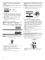
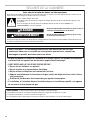
RANGE SAFETY
WARNING: If the information in these instructions is not followed exactly, a fire or
explosion may result causing property damage, personal injury or death.
– Do not store or use gasoline or other flammable vapors and liquids in the vicinity of this
or any other appliance.
– WHAT TO DO IF YOU SMELL GAS:
•
Do not try to light any appliance.
•
Do not touch any electrical switch.
•
Do not use any phone in your building.
•
Immediately call your gas supplier from a neighbor's phone. Follow the gas supplier's
instructions.
•
If you cannot reach your gas supplier, call the fire department.
– Installation and service must be performed by a qualified installer, service agency or
the gas supplier.
WARNING: Gas leaks cannot always be detected by smell.
Gas suppliers recommend that you use a gas detector approved by UL or CSA.
For more information, contact your gas supplier.
If a gas leak is detected, follow the “What to do if you smell gas” instructions.

3
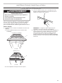
IMPORTANT: Do not install a ventilation system that blows air downward toward this gas cooking appliance. This type of
ventilation system may cause ignition and combustion problems with this gas cooking appliance resulting in personal injury or
unintended operation.
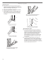
In the State of Massachusetts, the following installation instructions apply:
■ Installations and repairs must be performed by a qualified or licensed contractor, plumber, or gas fitter qualified or licensed by
the State of Massachusetts.
■ Acceptable Shut-off Devices: Gas Cocks and Ball Valves installed for use shall be listed.
■ A flexible gas connector, when used, must not exceed 4 feet (121.9 cm).
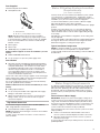
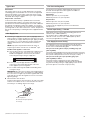
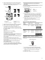
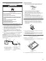
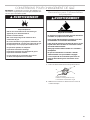
Tip Over Hazard
A child or adult can tip the range and be killed.
Install anti-tip bracket to floor or wall per installation instructions.
Slide range back so rear range foot is engaged in the slot of the anti-tip bracket.
Re-engage the anti-tip bracket if the range is moved.
Do not operate range without anti-tip bracket installed and engaged.
Failure to follow these instructions can result in death or serious burns to children and adults.
Anti-Tip
Bracket
To verify the anti-tip bracket is installed and engaged:
• Slide range forward.
• Look for the anti-tip bracket securely attached to floor or wall.
• See installation instructions for details.
Range Foot
WARNING
Slide range back so rear range foot is under anti-tip bracket.•

4
INSTALLATION REQUIREMENTS
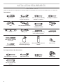
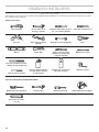
Tools and Parts
Gather the required tools and parts before starting installation. Read and follow the instructions provided with any tools listed here.
Tools Needed
For Propane/Natural Gas Conversions
Large flat-blade screwdriver Adjustable wrench T-20 Torx Driver Masking tape
1/2" (1.3 cm) open end
wrench
Pipe wrench Adjustable wrench or
5/8" (16 mm) wrench
1/8" x 4
1
/
4
" (3 mm x 100 mm)
flat-blade screwdriver
#2 Phillips screwdriver
Drill 3/8" (9.5 mm) drive ratchet 15/16" (24 mm)
combination wrench
Pliers
Level Tubing cutter 1/4" (6.4 mm), 3/8" (9.5 mm),
5/16" (7.9 mm) nut drivers
Marker or pencil
3/16" (4.8 mm) carbide tip
masonry bit
1/8" (3.2 mm) drill bit
Pipe-joint compound
resistant to propane gas
Noncorrosive leak-detection
solution
Tape measure

5
Parts Supplied
Check that all parts are included.
■ Anti-tip bracket kit
NOTE: Anti-tip bracket must be securely mounted to
subfloor. Thickness of flooring may require longer screws
to anchor bracket to subfloor. Longer screws are available
from your local hardware store. See the “Install Anti-Tip
Bracket” section.
■ Burner grates
■ Burner caps
■ Griddle drip tray (on griddle models)
Additional Parts Supplied on Steam-Assist Models (on some
models)
■ Model W10049700 water filter kit
■ 1/4" (6.4 mm) to 1/4" (6.4 mm) water supply union
Parts Needed
■ All models must be installed with a backguard if installing
at zero clearance to a combustible back wall surface such
as drywall. Alternatively, zero clearance to a back wall is
acceptable provided the surface of the entire back wall
above the range and below the hood is covered with a
non-combustible material such as tile or stainless steel.
See “Cabinet Dimensions” in the “Location Requirements”
section for installation requirements.
Check local codes and consult gas supplier. Check existing gas
supply and electrical supply. See the “Electrical Requirements”
and “Gas Supply Requirements” sections.
It is recommended that all electrical connections be made by
a licensed, qualified electrical installer.
Additional Parts Needed on Steam-Assist Models (on some
models)
■ Tubing staples/retainers
■ 1/4" (6.4 mm) O.D. flexible codes-approved water supply
tubing (to make water connection)
■ Water connection device (to connect 1/4" (6.4 mm) O.D.
tubing to water source). Check local codes for type of
connection required.
High Altitude Conversion
To convert the range for elevations above 6,560 ft (2000 m),
order a High Altitude Conversion Kit.
■ Part Number W11238043: High altitude kit
NOTE: Both propane and natural gas conversions are included
in the high altitude kit.
To order, see the “Assistance or Service” section of the Use
and Care Guide.
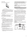
Water Filtration System Location
Requirements
(on some models)
For best results, do not install the water filtration system outside
or in extreme hot or cold temperatures. Temperature of water
supply to the water filtration system must be between 40°F (4°C)
and 100°F (38°C). Do not install on hot water supply line.
Locate the water filtration system near the cold water supply
pipe under the kitchen sink to filter cold water.
Make sure that the water filter assembly is installed in the upright
position.
It will be necessary to drill a 1/2" (1.3 cm) minimum diameter
hole in the upper-right or left rear corner of the side wall of the
cabinet under the sink to route the water supply tubing through
to the range.
Depending on your installation configuration, more routing holes
may be required.
Coil enough flexible codes-approved water supply tubing behind
the range to allow for the connection to the range to be made
behind the range prior to setting the range in place.
Typical Installation Configuration
NOTE: For unique installations, contact a licensed plumber.
In Massachusetts, a licensed plumber is required and the
Commonwealth of Massachusetts Plumbing Code 248-CMR will
be adhered to.
Water Supply Requirements
A cold water supply with water pressure between 30 and 120 psi
(207 and 827 kPa) is required to operate the steam feature. In
Massachusetts, plumbing code 248 CMR 3.00 and 10.00 must
be followed, and a licensed plumber will be used. If you have
questions about your water pressure, call a licensed, qualified
plumber.
Reverse Osmosis Water Supply
IMPORTANT: The pressure of the water supply coming out of
a reverse osmosis system going to the water inlet valve of the
range needs to be between 30 and 120 psi (207 and 827 kPa).
If a reverse osmosis water filtration system is connected to your
cold water supply, the water pressure to the reverse osmosis
system needs to be a minimum of 40 psi (276 kPa).
If the water pressure to the reverse osmosis system is less than
40 psi (276 kPa):
■ Check to see whether the sediment filter in the reverse
osmosis system is blocked. Replace the filter, if necessary.
■ Allow the storage tank on the reverse osmosis system to
refill after heavy usage.
If you have questions about your water pressure, call a licensed,
qualified plumber.
A
B
A. Anti-tip bracket
B. #8-18 x 1" (2.5 cm) Phillips head screws (4)
Cold water
supply
Hot
Cold
Filter
assembly
location

6
Location Requirements
IMPORTANT: Observe all governing codes and ordinances.
Do not obstruct flow of combustion and ventilation air.
■ It is the installer’s responsibility to comply with installation
clearances specified on the model/serial/rating plate. The
model/serial/rating plate is located under the console on
the right-hand side.
■ It is recommended that a 600 CFM (17.0 m
3
/hr) or larger
range hood be installed above the range.
■ It is not recommended that a microwave hood combination
be mounted above the range. Follow the range hood or
microwave hood combination installation instructions for
dimensional clearances above the cooktop surface.
■ Recessed installations must provide complete enclosure
of the sides and rear of the range.
■ All openings in the wall or floor where range is to be installed
must be sealed.
■ Do not seal the range to the side cabinets.
■ Cabinet opening dimensions that are shown must be used.
Given dimensions are minimum clearances.
■ The anti-tip bracket must be installed. To install the anti-tip
bracket shipped with the range, see the “Install Anti-Tip
Bracket” section.
■ Grounded electrical supply is required. See the “Electrical
Requirements” section.
■ Proper gas supply connection must be available. See the
“Gas Supply Requirements” section.
■ Contact a qualified floor covering installer to check that the
floor covering can withstand at least 200°F (93°C). Use an
insulated pad or 1/4" (6.4 mm) plywood over carpet and
under range if installing range over carpeting.
IMPORTANT: To avoid damage to your cabinets, check with
your builder or cabinet supplier to make sure that the materials
used will not discolor, delaminate, or sustain other damage. This
oven has been designed in accordance with the requirements
of UL and CSA International and complies with the maximum
allowable wood cabinet temperatures of 194°F (90°C).
Mobile Home - Additional Installation Requirements
The installation of this range must conform to the Manufactured
Home Construction and Safety Standard, Title 24 CFR,
Part 3280 (formerly the Federal Standard for Mobile Home
Construction and Safety, Title 24, HUD Part 280). When such
standard is not applicable, use the Standard for Manufactured
Home Installations, ANSI A225.1/NFPA 501A or local codes.
In Canada, the installation of this range must conform with
the current standards CAN/CSA-A240-latest edition or with
local codes.
Mobile Home Installations Require:
■ When this range is installed in a mobile home, it must be
secured to the floor during transit. Any method of securing
the range is adequate as long as it conforms to the
standards listed above.
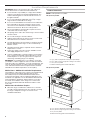
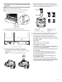
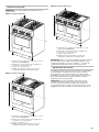
Product Dimensions
NOTE: Cooktop features may differ.
30" (76.2 cm) models
36" (91.4 cm) models
B
A
C
D
A. 27
3
/
4
" (70.5 cm) depth with control panel (See NOTE.)
B. 35
3
/
4
" (90.8 cm) range height when sitting on the wheels
C. 29
7
/
8
" (75.7 cm) width
D. Model/serial/rating plate location/SAID label
C
D
B
A
A. 27
1
⁄
8
" (68.9 cm) depth with control panel (See NOTE.)
B. 35
3
⁄
4
" (90.8 cm) range height when sitting on the wheels
C. 36" (91.4 cm) width
D. Model/serial/rating plate location/SAID label

7
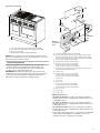
48" (121.9 cm) models
NOTE: When installed in a 24" (61.0 cm) base cabinet with 25"
(63.5 cm) countertop; front of oven door protrudes 1
7
/
8
" (4.8 cm)
beyond 24" (61.0 cm) base cabinet.
Cabinet Requirements
Cabinet opening dimensions shown are for 25" (64.0 cm)
countertop depth, 24" (61.0 cm) base cabinet depth, and
36" (91.4 cm) countertop height. Dimensions must be met
in order to ensure a flush fit to back wall.
IMPORTANT: If installing a range hood or microwave hood
combination above the cooking surface, follow the range hood
or microwave hood combination installation instructions for
dimensional clearances above the cooking surface.
** Minimum Clearances
30" (76.2 cm) models: 42" (106.7 cm) minimum clearance
between the top of the cooking platform and the bottom of a
combustible surface
36" (91.4 cm) models: 58" (147.3 cm) minimum clearance
between the top of the cooking platform and the bottom of a
combustible surface
48" (121.9 cm) models: 58" (147.3 cm) minimum clearance
between the top of the cooking platform and the bottom of a
combustible surface
*** If the surface of the back wall is constructed of a combustible
material and a backguard is not installed, a 6" (15.2 cm)
minimum clearance is required for all models.
C
D
B
A
A. 27
1
⁄
8
" (68.9 cm) depth with control panel (See NOTE.)
B. 35
3
⁄
4
" (90.8 cm) range height when sitting on the wheels
C. 48" (121.9 cm) width
D. Model/serial/rating plate location/SAID label
M
K
N
G
I
F
D
E
B
C
**
A
H
I
L
J
Electrical
installation
area*
Gas
installation
area
J
F
O***
A. 18" (45.7 cm) upper cabinet to countertop
B. 30" (76.2 cm) model: 30" (76.2 cm) min. upper cabinet width
36" (91.4 cm) model: 36" (91.4 cm) min. upper cabinet width
48" (121.9 cm) model: 48" (121.9 cm) min. upper cabinet width
C. 13" (33 cm) max. upper cabinet depth
D. For minimum clearance to top of range.**
E. 30" (76.2 cm) on 30" (76.2 cm) models
36" (91.4 cm) on 36" (91.4 cm) models
48" (121.9 cm) on 48" (121.9 cm) models
F. 12" (30.4 cm) min. clearance from both sides of range to side
wall or other combustible material
G. 15" (38.1 cm)
H. 22" (55.9 cm) on 30" (76.2 cm) models
28" (71.1 cm) on 36" (91.4 cm) models
40" (101.6 cm) on 48" (121.9 cm) models
I. 4" (10.1 cm)
J. 3" (7.6 cm)
K. 5" (12.7 cm)
L. 6" (15.2 cm) on 30" (76.2 cm) models
14" (35.5 cm) on 36" (91.4 cm) models
24" (61.0 cm) on 48" (121.9 cm) models
M. 10
1
/
2
" (26.7 cm)
N. 6" (15.2 cm)
O. 6" (15.2 cm)***

8
Electrical Requirements:
U.S.A. Only
If codes permit and a separate ground wire is used, it is
recommended that a qualified electrical installer determine
that the ground path and wire gauge are in accordance with
local codes.
If codes permit and a separate ground wire is used, it is
recommended that a qualified electrician determine that
the ground path is adequate.
Do not use an extension cord.
Be sure that the electrical connection and wire size are adequate
and in conformance with the National Electrical Code, ANSI/
NFPA 70 — latest edition — and all local codes and ordinances.
A copy of the above code standards can be obtained from:
National Fire Protection Association
1 Batterymarch Park
Quincy, MA 02169-7471
WARNING: Improper connection of the equipment-grounding
conductor can result in a risk of electric shock. Check with a
qualified electrician or service technician if you are in doubt as
to whether the appliance is properly grounded. Do not modify
the power supply cord plug. If it will not fit the outlet, have a
proper outlet installed by a qualified electrician.
Electrical Connection
To properly install your range, you must determine the type of
electrical connection you will be using and follow the instructions
provided for it here.
■ Range must be connected to the proper electrical voltage
and frequency as specified on the model/serial/rating plate.
The model/serial/rating plate is located under the console
on the right-hand side. Refer to the illustrations in “Product
Dimensions” in the “Location Requirements” section.
■ This range is manufactured with a 4-wire power supply cord.
■ A circuit breaker is recommended.
■ Wire sizes and connections must conform with the rating
of the range.
NOTE: If your home does not have a 4-wire system, consult
your local qualified electrician.
Electrical Requirements:
Canada Only
If codes permit and a separate ground wire is used, it is
recommended that a qualified electrical installer determine
that the ground path and wire gauge are in accordance with
local codes.
Be sure that the electrical connection and wire size are adequate
and in conformance with the CSA Standard C22.1, Canadian
Electrical Code, Part 1 — latest edition — and all local codes
and ordinances.
A copy of the above code standards can be obtained from:
Canadian Standards Association
178 Rexdale Blvd.
Toronto, ON M9W 1R3 CANADA
■ Check with a qualified electrical installer if you are not sure
the range is properly grounded.
■ When a 4-wire, single-phase 250 V, 60 Hz, AC-only electrical
supply is available, a 40 A minimum circuit protection is
required on 30" (76.2 cm) and 36" (91.4 cm) ranges and a
50 A minimum circuit protection is required on 48"
(121.9 cm) ranges, fused on both sides of the line.
■ A time-delay fuse or circuit breaker is recommended.
■ This range is equipped with a CSA International Certified
Power Cord intended to be plugged into a standard 14-50R
wall receptacle. Be sure the wall receptacle is within reach of
range’s final location.
■ Do not use an extension cord.
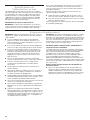
Gas Supply Requirements
Observe all governing codes and ordinances.
IMPORTANT: This installation must conform with all local codes
and ordinances. In the absence of local codes, installation must
conform with American National Standard, National Fuel Gas
Code ANSI Z223.1 — latest edition — or CAN/CGA B149 —
latest edition.
IMPORTANT: Range must be connected to a regulated
gas supply.
IMPORTANT: Leak testing of the range must be conducted
according to the manufacturer’s instructions.
WARNING
Electrical Shock Hazard
Electrically ground range.
Failure to do so can result in death, fire, or
electrical shock.
WARNING
Explosion Hazard
Use a new CSA International approved gas supply line.
Install a shut-off valve.
Securely tighten all gas connections.
If connected to propane, have a qualified person make
sure gas pressure does not exceed 14" (36 cm) water
column.
Examples of a qualified person include:
licensed heating personnel,
authorized gas company personnel, and
authorized service personnel.
Failure to do so can result in death, explosion, or fire.

9
Type of Gas
Natural Gas:
This range is factory set for use with Natural gas. The model/
serial/rating plate, located under the console on the right-hand
side, has information on the types of gas that can be used. If
the types of gas listed do not include the type of gas available,
check with the local gas supplier.
Propane Gas conversion:
Conversion must be done by a qualified service technician.
No attempt shall be made to convert the range from the gas
specified on the model/serial/rating plate for use with a different
gas without consulting the serving gas supplier. To convert to
Propane gas, use the Propane gas conversion kit provided with
your range and see the “Gas Conversions” section. The parts for
this kit are in the package containing literature supplied with the
range.
Gas Supply Line
■ Provide a gas supply line of 3/4" (1.9 cm) rigid pipe to the
range location. A smaller size pipe on longer runs may result
in insufficient gas supply. With Propane gas, piping or tubing
size can be 1/2" (1.3 cm) minimum. Usually, Propane gas
suppliers determine the size and materials used in the
system.
NOTE: Pipe-joint compounds that resist the action of
Propane gas must be used. Do not use TEFLON
®†
tape.
Flexible metal appliance connector:
■ If local codes permit, a new CSA design-certified, 4-5 ft
(122-152 cm) long, 5/8" (1.6 cm) or 3/4" (1.9 cm) I.D.,
flexible metal appliance connector may be used for
connecting the range to the gas supply line.
■ A 1/2" (1.3 cm) male pipe thread is needed for
connection to the female pipe threads of the inlet
to the appliance pressure regulator.
■ Do not kink or damage the flexible metal tubing when
moving the range.
IMPORTANT: All connections must be wrench-tightened. Do
not make connections to the gas regulator too tight. Making
the connections too tight may crack the regulator and cause
a gas leak. Do not allow the regulator to turn or move when
tightening fittings.
■ Must include a shut-off valve:
Install a manual gas line shut-off valve in an easily accessible
location. Do not block access to shut-off valve. The valve is
for turning on or shutting off gas to the range.
Gas Pressure Regulator
The gas pressure regulator supplied with this range must
be used. The inlet pressure to the regulator should be as
follows for proper operation:
Natural Gas:
Minimum pressure: 5" (12.7 cm) WCP
Maximum pressure: 14" (35.6 cm) WCP
Propane Gas:
Minimum pressure: 10" (25.4 cm) WCP
Maximum pressure: 14" (35.6 cm) WCP
Contact local gas supplier if you are not sure about the
inlet pressure.
Burner Input Rating — Altitude
Input ratings shown on the model/serial/rating plate are for
elevations up to 2,000 ft (609.6 m).
For elevations above 2,000 ft (609.6 m), ratings need to be
reduced at a rate of 4% for each 1,000 ft (304.8 m) above
sea level (not applicable for Canada).
Gas Supply Pressure Testing
Gas supply pressure for testing regulator must be at least 1"
(2.5 cm) water column pressure above the manifold pressure
shown on the model/serial/rating plate.
Line pressure testing above 1/2 psi (3.5 kPa) gauge (14"
[35.6 cm] WCP)
The range and its individual shut-off valve must be disconnected
from the gas supply piping system during any pressure testing of
that system at test pressures in excess of 1/2 psi (3.5 kPa).
Line pressure testing at 1/2 psi (3.5 kPa) gauge (14"
[35.6 cm] WCP) or lower
The range must be isolated from the gas supply piping
system by closing its individual manual shut-off valve during
any pressure testing of the gas supply piping system at test
pressures equal to or less than 1/2 psi (3.5 kPa).
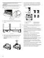
A
B
C
A. Gas supply line
B. Shut-off valve open position
C. To range
†
®
TEFLON is a registered trademark of Chemours.

10
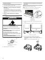
INSTALLATION INSTRUCTIONS
Unpack the Range
Remove shipping materials, tape, and film from range.
Keep shipping pallet under range. Remove oven racks, and parts
package from inside oven. Remove grates from top of oven.
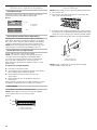
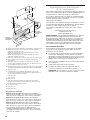
Remove Kick Plate
1. Your range will have the kick plate packaged on top of the
unit.
a. Remove kick plate from top of range and grate pack.
b. Lay kick plate to the side to avoid scratching.
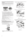
2. For 48" (121.9 cm) models only, rotate center support
counterclockwise off the pallet until it stops.
NOTE: This support is used only for shipping and is not
needed for installation.
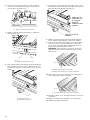
3. Lay a piece of cardboard from packaging on the floor behind
range. Using two or more people, firmly grasp each side of
range. Lift range up about 3" (8.0 cm) and move it back until
range is off shipping pallet. Set range on cardboard to avoid
damaging floor.
WARNING
Excessive Weight Hazard
Use two or more people to move and install range.
Failure to do so can result in back or other injury.
In packaging
A. Kick plate
A
Packaging removed
A. Kick plate
A

11
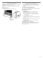
Remove Door
Door Removal
■ Do not remove the side door spacers until the range is ready
to install. Removing the door spacers could allow the door to
shift, damaging the door latch.
■ Do not lift or move the range by the door handle(s) or control
panel.
■ Prior to installing the range, you will need to remove the oven
door(s). Prepare a surface where you will place the door(s).
This surface should be flat and covered with a soft blanket,
or use the corner posts from the packaging material.
Replace the Door
■ To replace the oven door(s), locate the slots in the oven
cavity for the hinge locks and repeat the steps above in
reverse order. Make sure the door closes properly and there
is no interference from the door latch. If necessary, remove
the door and repeat the steps above. If power is connected
to the range, open and close the door to make sure the oven
light comes on and goes off appropriately.
■ The range is equipped with leveling legs and rollers. Once
the range is removed from the shipping pallet, make sure the
leveling legs are not touching the floor and use the rollers
to move the range into position. Always cover the flooring
surface to avoid damage to the floor. Do not roll the range
directly on the floor.
A
A. Oven door hinge in the
locked position
B
B. Oven door hinge in the
unlocked position
Partially close the door to engage the
door latch locks. The door will stop at
this point.
Use two hands to remove and replace
the oven door(s). It may be necessary to
gently shift door from side to side.
A
A. Slot in the oven frame for the
door hinge lock

12
GAS CONVERSIONS
IMPORTANT: Gas conversions from Natural gas to Propane gas
must be done by a qualified installer.
Propane Gas Conversion
1. Turn the manual shut-off valve to the closed position.
2. Unplug range or disconnect power.
WARNING
Explosion Hazard
Use a new CSA International approved gas supply line.
Install a shut-off valve.
Securely tighten all gas connections.
If connected to propane, have a qualified person make
sure gas pressure does not exceed 14" (36 cm) water
column.
Examples of a qualified person include:
licensed heating personnel,
authorized gas company personnel, and
authorized service personnel.
Failure to do so can result in death, explosion, or fire.
WARNING
Tip Over Hazard
A child or adult can tip the range and be killed.
Install anti-tip bracket to floor or wall per installation
instructions.
Slide range back so rear range foot is engaged in the
slot of the anti-tip bracket.
Re-engage anti-tip bracket if range is moved.
Do not operate range without anti-tip bracket installed
and engaged.
Failure to follow these instructions can result in death
or serious burns to children and adults.
A
B
C
A. To range
B. Shut-off valve (closed position)
C. Gas supply line

13
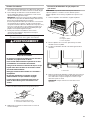
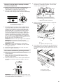
To Convert Gas Pressure Regulator from Natural Gas
to Propane
NOTE: Door must be removed in order to remove or replace kick
plate. Refer to the “Remove Door” section.
Align kick plate over the kick plate slots and push kick plate
down.
1. Lift the kick plate up and off of the kick plate tab.
2. Gently lay kick plate aside to avoid scratching.
3. Locate the gas pressure regulator at the left rear of the range.
4. Remove the gas pressure regulator cap by using a
large flat-blade screwdriver, turning the regulator cap
counterclockwise. When the cap is removed, do not lose the
metal seal.
NOTE: Do not remove the spring beneath the cap.
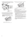
5. Remove spring retainer from the cap by turning the spring
retainer counterclockwise. Locate the “LP” and “NAT”
position on the spring retainer. Turn over the spring retainer
so the “LP” arrow is pointing toward the cap.
6. Tighten the gas pressure regulator cap by using a large flat-
blade screwdriver, turning the regulator cap clockwise.
7. Test the gas pressure regulator and gas supply line.
The regulator must be checked at a minimum 1” (2.5 cm)
water column above the set pressure. The inlet pressure to
the regulator should be as follows for operation and checking
the regulator setting:
Propane Gas:
Minimum pressure: 10" (25.4 cm) WCP
Maximum pressure: 14" (35.6 cm) WCP
Gas Supply Pressure Testing
Gas supply pressure for testing regulator must be at least 1"
(2.5 cm) water column pressure above the manifold pressure
shown on the model/serial/rating plate.
Line pressure testing above 1/2 psi (3.5 kPa) gauge (14"
[35.6 cm] WCP)
The range and its individual shut-off valve must be
disconnected from the gas supply piping system during
any pressure testing of that system at test pressures in
excess of 1/2 psi (3.5 kPa).
Line pressure testing at 1/2 psi (3.5 kPa) gauge (14"
[35.6 cm] WCP) or lower
The range must be isolated from the gas supply piping
system by closing its individual manual shut-off valve during
any pressure testing of the gas supply piping system at test
pressures equal to or less than 1/2 psi (3.5 kPa).
A
B
C
A. Kick plate
B. Kick plate tab
C. Kick plate slot
A
A. Gas pressure regulator
LP
NAT
LP
NAT
LP
NAT
LP
NAT
A
B
C
DE
A. Access cap
B. Metal seal
C. Gas pressure regulator
D. Spring retainer in NAT
position
E. Spring retainer in LP
position

14
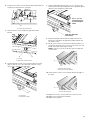
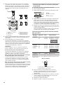
To Convert Surface Burners from Natural Gas to
Propane
1. If the burner grates are installed, remove them.
2. Remove burner cap.
3. Remove the burner base by first removing (2) T-20 screws.
A
C
B
Burner
A. Burner cap
B. Screws
C. Burner base
4. Apply masking tape to the end of a 1/4" (7 mm) nut driver
to help hold the gas orifice spud in the nut driver while
changing it. Insert nut driver into the gas opening and press
down onto the gas orifice spud and remove by turning the
gas orifice spud counterclockwise and lifting out. Set gas
orifice spud aside.
5. Replace with correct Propane gas orifice spud. See the
“Propane Gas Orifice Spud/Hood Chart”.
Use the following chart to find the exact orifice spud
placement.
Propane Gas Orifice Spud/Hood Chart
Burner
Rating
Stamp Size Burner Style
7,400 BTUs 70
44
0.70 mm
0.44 mm
Small burner - main
Small burner - simmer
13,000 BTUs 99
50
0.99 mm
0.50 mm
Large burner – main
Larger burner – simmer
16,000 BTUs 116 1.16 mm Grill burner
NOTE: Refer to serial tag for more information on burner ratings
and locations.
Burner orifice spud
6. Place Natural gas orifice in plastic parts bag for future use
and keep with package containing literature.
NOTE: There may be extra orifices in your kit.
7. Replace the burner base and screws. Tighten screws only
until burner is snug to cooktop, do not over-tighten.
8. Replace burner cap.
9. Repeat steps 2 through 8 for the remaining burners.
Adjusting Simmer Low Setting on Surface Burner for
Propane
1. Remove the surface burner control knobs and bezels (oven
control knobs and griddle control knobs do not have to be
removed).
2. Locate the Simmer low-turndown adjustment screw through
the bezel on the left side of the ignition switch.
3. With the burner ON, and set to Simmer Lo, adjust the
simmer flame down to the proper BTU level. Using a
1/8" x 4
1
/
4
" (3.2 mm x 108 mm) flat blade screwdriver, turn
the simmer low-turndown adjustment screw clockwise until
the flame height is below the bottom of the cap. If the flame
becomes unstable and flickers or appears to race around the
burner, the adjustment is too low and the screw should be
adjusted counterclockwise until the flame is stable. Repeat
this step for all surface burners, except the grill burner.
NOTE: Use a knob to adjust the burner valve.
NOTE: If your range has the IR grill, then skip ahead to the
Convert IR Grill Burner section.
NOTE: Adjust each burner individually.
4. Replace the bezels using the 2 screws which attach to the
valve brackets.
5. Push the surface knobs onto the valve stems.
6. Replace burner grates.
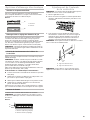
To Convert IR Grill Burner for Propane
1. Unplug range or disconnect power.
2. Remove grill knob and bezel. The other surface knobs and
bezels should still be off the range.
3. Open the oven door and remove the two screws on each
side of the range that hold the control console in place.
NOTE: Make sure to leave oven door open or the control
console will not rest in the side brackets properly once it is
detached.
A
B
A. Size stamp
B. Fuel type stamp (L or N)
AB
A. Simmer low-turndown adjustment screw
B. Ignition switch

15
4. Pull up on the control console and let it drop forward into the
notched console brackets on each side.
5. Remove the two screws holding the grill orifice holder
bracket.
6. Pull the grill orifice holder out of the burner box far enough
away to allow access to the orifice with a wrench, using
caution not to kink the attached tubing.
7. Using an adjustable wrench and a 1/2" (1.3 cm) open end
wrench remove the Natural (NG) gas orifice spud and replace
with the correct Propane (L) orifice spud.
8. Reposition the grill orifice holder assembly back into the
burner box, and replace the grill orifice holder bracket and
two holder screws.
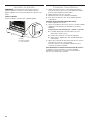
9. Lift up on the control console and set it back into place. For
a proper fit, the flange of the control console must hook over
the lip on the front of the range cooktop.
NOTE: It may be necessary to lift valve stems to align with
console holes.
10. Check that the control console is flush with the top edge of
the range.
11. Replace the screws on each side of the control console.
12. Replace the control knobs and bezels.
13. Replace burner grates.
A
A. Control console bracket
A
B
A. Screws
B. Grill orifice holder bracket
A
B
A. Grill orifice
B. Grill orifice holder
Use ¹/₂" (1.3 cm)
open end wrench
to remo
ve/replace
orifice
Hold with adjustable
wrench here
A
B
A. Control console flange
B. Front lip of range cooktop
A
A. Flush with range top

16
Complete Installation
1. Refer to the “Make Gas Connection” section for properly
connecting the range to the gas supply.
2. Refer to the “Electronic Ignition System” section for proper
burner ignition, operation, and burner flame adjustments.
IMPORTANT: You may have to adjust the “LO” setting for
each range burner.
Checking for proper range burner flame is very important.
The small inner cone should have a very distinct blue flame
1/4" (6.4 mm) to 1/2" (1.3 cm) long. The outer cone is not as
distinct as the inner cone. Propane gas flames have a slightly
yellow tip.
3. Refer to “Complete Installation” in the “Installation
Instructions” section of this manual to complete this
procedure.
Natural Gas Conversion
1. Turn the manual shut-off valve to the closed position.
2. Unplug range or disconnect power.
To Convert Gas Pressure Regulator from Propane to
Natural Gas
NOTE: Door must be removed in order to remove or replace kick
plate. Refer to the “Remove Door” section.
Align kick plate over the kick plate slots and push kick plate
down.
1. Lift the kick plate up and off of the kick plate tab.
2. Gently lay kick plate aside to avoid scratching the stainless
steel.
3. Locate the gas pressure regulator at the left rear of the range.
4. Remove the gas pressure regulator cap by using a
large flat-blade screwdriver, turning the regulator cap
counterclockwise. When the cap is removed, do not lose the
metal seal.
NOTE: Do not remove the spring beneath the cap.
WARNING
Tip Over Hazard
A child or adult can tip the range and be killed.
Install anti-tip bracket to floor or wall per installation
instructions.
Slide range back so rear range foot is engaged in the
slot of the anti-tip bracket.
Re-engage anti-tip bracket if range is moved.
Do not operate range without anti-tip bracket installed
and engaged.
Failure to follow these instructions can result in death
or serious burns to children and adults.
A
B
C
A. To range
B. Shut-off valve (closed position)
C. Gas supply line
A
B
C
A. Kick plate
B. Kick plate tab
C. Kick plate slot
A
A. Gas pressure regulator

17
5. Remove spring retainer from the cap by turning the spring
retainer counterclockwise. Locate the “LP” and “NAT”
position on the spring retainer. Turn over the spring retainer
so the “NAT” arrow is pointing toward the cap.
6. Tighten the gas pressure regulator cap by using a large flat-
blade screwdriver, turning the regulator cap clockwise.
7. Test the gas pressure regulator and gas supply line.
The regulator must be checked at a minimum 1" (2.5 cm)
water column above the set pressure. The inlet pressure to
the regulator should be as follows for operation and checking
the regulator setting:
Natural Gas:
Minimum pressure: 5" (12.7 cm) WCP
Maximum pressure: 14" (35.6 cm) WCP
Gas Supply Pressure Testing
Gas supply pressure for testing regulator must be at least 1"
(2.5 cm) water column pressure above the manifold pressure
shown on the model/serial/rating plate.
Line pressure testing above 1/2 psi (3.5 kPa) gauge (14"
[35.6 cm] WCP)
The range and its individual shut-off valve must be
disconnected from the gas supply piping system during any
pressure testing of that system at test pressures in excess of
1/2 psi (3.5 kPa).
Line pressure testing at 1/2 psi (3.5 kPa) gauge (14"
[35.6 cm] WCP) or lower
The range must be isolated from the gas supply piping
system by closing its individual manual shut-off valve during
any pressure testing of the gas supply piping system at test
pressures equal to or less than 1/2 psi (3.5 kPa).
To Convert Surface Burners from Propane to
Natural Gas
1. If the burner grates are installed, remove them.
2. Remove burner cap.
3. Remove the burner base by first removing (2) T-20 screws.
A
C
B
Burner
A. Burner cap
B. Screws
C. Burner base
4. Apply masking tape to the end of a 1/4" (7 mm) nut driver
to help hold the gas orifice spud in the nut driver while
changing it. Insert nut driver into the gas opening and press
down onto the gas orifice spud and remove by turning the
gas orifice spud counterclockwise and lifting out. Set gas
orifice spud aside.
5. Replace with correct Natural gas orifice spud. See the
“Natural Gas Orifice Spud/Hood Chart.”
Use the following chart to find the exact orifice spud
placement.
Natural Gas Orifice Spud/Hood Chart
Burner
Rating
Stamp Size Burner Style
9,200 BTUs 130
70
1.30 mm
0.70 mm
Small burner - main
Small burner - simmer
18,000 BTUs
(REAR)
20,000 BTUs
(FRONT)
193
78
203
78
1.93 mm
0.78 mm
2.03 mm
0.78 mm
Large burner – main
Large burner – simmer
Large burner – main
Large burner – simmer
16,000 BTUs 180 1.80 mm Grill burner
NOTE: Refer to serial tag for more information on burner ratings
and locations.
Burner orifice spud
6. Place Propane gas orifice spuds in plastic parts bag for
future use and keep with package containing literature.
7. Replace the burner base and screws. Tighten screws only
until burner is snug to cooktop, do not over-tighten.
8. Replace burner cap.
9. Repeat steps 2 through 8 for the remaining burners.
LP
NAT
LP
NAT
LP
NAT
LP
NAT
A
B
C
DE
A. Access cap
B. Metal seal
C. Gas pressure regulator
D. Spring retainer in LP
position
E. Spring retainer in NAT
position
A
B
A. Size stamp
B. Fuel type stamp (L or N)

18
Adjusting Simmer Low Setting on Surface Burner for
Natural Gas
1. Remove the surface burner control knobs and bezels (oven
control knobs and griddle control knobs do not have to be
removed).
2. Locate the Simmer low-turndown adjustment screw through
the bezel on the left side of the ignition switch.
3. With the burner ON, and set to Simmer Lo, adjust the
simmer flame down to the proper BTU level. Using a
1/8" x 4
1
/
4
" (3.2 mm x 108 mm) flat blade screwdriver,
turn the simmer low-turndown adjustment screw
counterclockwise until the flame becomes stable, does not
flicker, or appear to race around the burner. Once the flame
is stable, turn the burner rate to SIMMER HIGH setting. The
flame should increase to approximately 2X the flame height.
If not, the low-turndown may be able to be adjusted low and
still remain stable. Repeat this step for all surface burners,
except the grill burner.
NOTE: Use a knob to adjust the burner valve.
NOTE: If your range has the IR grill, then skip ahead to the
Convert IR Grill Burner section.
NOTE: Adjust each burner individually.
4. Replace the bezels using the 2 screws which attach to the
valve brackets.
5. Push the surface knobs onto the valve stems.
6. Replace burner grates.
To Convert IR Grill Burner for Natural Gas
1. Unplug range or disconnect power.
2. Remove grill knob and bezel. The other surface knobs and
bezels should still be off the range.
3. Open the oven door and remove the two screws on each
side of the range that hold the control console in place.
NOTE: Make sure to leave oven door open or the control
console will not rest in the side brackets properly once it is
detached.
4. Pull up on the control console and let it drop forward into the
notched console brackets on each side.
5. Remove the two screws holding the grill orifice holder
bracket.
6. Pull the grill orifice holder out of the burner box far enough
away to allow access to the orifice with a wrench, using
caution not to kink the attached tubing.
AB
A. Simmer low-turndown adjustment screw
B. Ignition switch
A
A. Control console bracket
A
B
A. Screws
B. Grill orifice holder bracket
A
B
A. Grill orifice
B. Grill orifice holder

19
7. Using an adjustable wrench and a 1/2" (1.3 cm) open end
wrench remove the Propane (L) orifice spud and replace with
the correct Natural Gas (NG) orifice spud. See Natural Gas
Orifice Spud Chart.
8. Reposition the grill orifice holder assembly back into the
burner box, and replace the grill orifice holder bracket and
two holder screws.
9. Lift up on the control console and set it back into place. For
a proper fit, the flange of the control console must hook over
the lip on the front of the range cooktop.
NOTE: It may be necessary to lift valve stems to align with
console holes.
10. Check that the control console is flush with the top edge of
the range.
11. Replace the screws on each side of the control console.
12. Replace the control knobs and bezels.
13. Replace burner grates.
Complete Installation
1. Refer to the “Make Gas Connection” section for properly
connecting the range to the gas supply.
2. Refer to the “Electronic Ignition System” section for proper
burner ignition, operation, and burner flame adjustments.
IMPORTANT: You may have to adjust the “LO” setting for
each range burner.
Checking for proper range burner flame is very important.
The small inner cone should have a very distinct blue flame
1/4" (6.4 mm) to 1/2" (1.3 cm) long. The outer cone is not as
distinct as the inner cone. Propane gas flames have a slightly
yellow tip.
3. Refer to “Complete Installation” in the “Installation
Instructions” section of this manual to complete this
procedure.
Use ¹/₂" (1.3 cm)
open end wrench
to remo
ve/replace
orifice
Hold with adjustable
wrench here
A
B
A. Control console flange
B. Front lip of range cooktop
A
A. Flush with range top

20
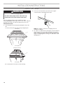
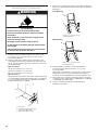
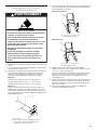
Install Anti-Tip Bracket
1. Determine which mounting method to use: floor or wall.
If you have a stone or masonry floor, you can use the
wall mounting method.
2. Determine and mark centerline of the cutout space. The
mounting bracket must be installed on the right side of the
cutout. Position mounting bracket in cutout as shown in the
following illustration.
Measurement B:
30" (76.2 cm) ranges: 14
1
⁄
4
" (36.1 cm)
36" (91.4 cm) ranges: 17
1
⁄
4
" (43.8 cm)
48" (121.9 cm) ranges: 23
3
⁄
8
" (59.3 cm)
Measurement C:
Optional distance from back wall. If back wall is constructed
of a combustible material and a backguard is not installed, a
6" (15.2 cm) minimum clearance is required for all models.
Install anti-tip bracket accordingly.
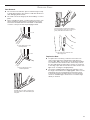
3. Drill two 1/8" (3.0 mm) holes that correspond to the bracket
holes of the determined mounting method. See the following
illustrations.
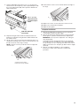
Floor Mounting
Wall Mounting
4. Using a Phillips screwdriver, mount anti-tip bracket
to the wall or floor with the two #12 x 1
5
⁄
8
" (4.1 cm)
screws provided.
Depending on the thickness of your flooring, longer screws
may be necessary to anchor the bracket to the subfloor.
Longer screws are available from your local hardware store.
5. Move range close enough to opening to allow for electrical
connections to be made. Remove shipping base, cardboard,
or hardboard from under range.
6. Continue installing your range using the following
installation instructions.
WARNING
Tip Over Hazard
A child or adult can tip the range and be killed.
Install anti-tip bracket to floor or wall per installation
instructions.
Slide range back so rear range foot is engaged in the
slot of the anti-tip bracket.
Re-engage anti-tip bracket if range is moved.
Do not operate range without anti-tip bracket installed
and engaged.
Failure to follow these instructions can result in death
or serious burns to children and adults.
A
B
C
A. Centerline
B. Centerline of cutout to outside
edge of anti-tip bracket
C. Back wall to back of range
B
A
A. #12 x 1
5
⁄
8
" (4.1 cm) screws
B. Anti-tip bracket
B
A
A. #12 x 1
5
⁄
8
" (4.1 cm) screws
B. Anti-tip bracket
La page est en cours de chargement...
La page est en cours de chargement...
La page est en cours de chargement...
La page est en cours de chargement...
La page est en cours de chargement...
La page est en cours de chargement...
La page est en cours de chargement...
La page est en cours de chargement...
La page est en cours de chargement...
La page est en cours de chargement...
La page est en cours de chargement...
La page est en cours de chargement...
La page est en cours de chargement...
La page est en cours de chargement...
La page est en cours de chargement...
La page est en cours de chargement...
La page est en cours de chargement...
La page est en cours de chargement...
La page est en cours de chargement...
La page est en cours de chargement...
La page est en cours de chargement...
La page est en cours de chargement...
La page est en cours de chargement...
La page est en cours de chargement...
La page est en cours de chargement...
La page est en cours de chargement...
La page est en cours de chargement...
La page est en cours de chargement...
-
 1
1
-
 2
2
-
 3
3
-
 4
4
-
 5
5
-
 6
6
-
 7
7
-
 8
8
-
 9
9
-
 10
10
-
 11
11
-
 12
12
-
 13
13
-
 14
14
-
 15
15
-
 16
16
-
 17
17
-
 18
18
-
 19
19
-
 20
20
-
 21
21
-
 22
22
-
 23
23
-
 24
24
-
 25
25
-
 26
26
-
 27
27
-
 28
28
-
 29
29
-
 30
30
-
 31
31
-
 32
32
-
 33
33
-
 34
34
-
 35
35
-
 36
36
-
 37
37
-
 38
38
-
 39
39
-
 40
40
-
 41
41
-
 42
42
-
 43
43
-
 44
44
-
 45
45
-
 46
46
-
 47
47
-
 48
48


JennAir JDSP536HL Guide d'installation
- Catégorie
- Cuisinières
- Taper
- Guide d'installation
dans d''autres langues
- English: JennAir JDSP536HL Installation guide
Documents connexes
Autres documents
-
KitchenAid KFGC558JMH Guide d'installation
-
KitchenAid KFGC558JMH Guide d'installation
-
KitchenAid KDRU767VSS Guide d'installation
-
KitchenAid KDRU763VSS Guide d'installation
-
KitchenAid KDRS407VSS Guide d'installation
-
KitchenAid KDRS407VSS00 Guide d'installation
-