Sauder 414129 Assembly Instruction Manual
- Taper
- Assembly Instruction Manual

sauder.com
Twin Platform Bed
with Headboard
Parklane Collection | Model 414129
NOTE: THIS INSTRUCTION
BOOKLET CONTAINS IMPORTANT
SAFETY INFORMATION.
PLEASE READ AND KEEP FOR
FUTURE REFERENCE.
English pg 1-20
Français pg 21-23
Español pg 24-26
Lot # 530074 05/28/19
Purchased: __________________
sauder.com
CONTACT US FIRST
BEFORE MAKING ANY RETURNS TO THE STORE.
Share your journey!
sauder.com
CONTACT US FIRST
BEFORE MAKING ANY RETURNS TO THE STORE.
Visit sauder.com/service to order replacement parts, view video assembly tips, or chat with a live rep.
Prefer the phone? Give us a ring at
1-800-523-3987.
Customer Service is available Monday-Friday - 9 a.m. to 5:30 p.m. EST (except holidays)
WARNING
CHOKING HAZARD - Small Parts
Not for children under 3 years.
Adult assembly required.

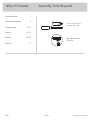
Table of Contents Assembly Tools Required
3
4
5-20
21-23
24-26
27
Part Identifi cation
Hardware Identifi cation
Assembly Steps
Français
Español
Warranty
No. 2 Phillips Screwdriver
Tip Shown Actual Size
Skip the power trip.
This time.
414129 www.sauder.com/servicePage 2

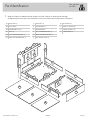
Part Identifi cation
å While not all parts are labeled, some of the parts will have a label or an inked letter on the edge
to help distinguish similar parts from each other. Use this part identifi cation to help identify similar parts.
A3 RIGHT END (1)
B3 LEFT END (1)
E3 HEADBOARD TOP (1)
I3 SLAT (2)
N2 LEFT FOOTBOARD RAIL (1)
O2 RIGHT FOOTBOARD RAIL (1)
Q SUPPORT (4)
R FOOTBOARD (1)
S HEADBOARD (1)
T LEFT HEADBOARD RAIL (1)
U RIGHT HEADBOARD RAIL (1)
V LEFT/RIGHT BACK (2)
W PLATFORM (3)
X SMALL SUPPORT (4)
Y LARGE SUPPORT (2)
Z CENTER BACK (1)
Now you know
our ABCs.
414129www.sauder.com/service
Page 3
A3
B3
X
Y
E3
Z
U
Q
W
R
S
T
N2
V
V
W
W
I3
I3
Y
Q
Q
Q
X
X
O2
X

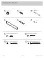
Hardware Identifi cation
å Screws are shown actual size. You may receive extra hardware with your unit.
414129 www.sauder.com/servicePage 4
Z-PLATE - 2
75G
FELT DISC CARD - 2
1M
HIDDEN CAM - 4
1F
WOOD DOWEL - 2
15F
BI-CAM DOWEL - 2
25F
METAL PIN - 8
1R
BLACK 9/16" LARGE HEAD SCREW - 36
1S 12S
BROWN 1" FLAT HEAD SCREW - 52
BLACK 1-1/2" FLAT HEAD SCREW - 16
101S
BLACK 1-15/16" FLAT HEAD SCREW - 20
113S

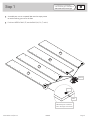
Step 1
Look for this icon. It means a
video assembly tip is available at
www.sauder.com/service/tips
å
Assemble your unit on a carpeted fl oor or on the empty carton
to avoid scratching your unit or the fl oor.
å
Push four HIDDEN CAMS (1F) into the RAILS (N2, O2, T, and U).
414129www.sauder.com/service
Page 5
U
T
N2
O2
Arrow
1F
Arrow
The arrow in the HIDDEN
CAM must point toward the
hole in the edge of the board.
Hole

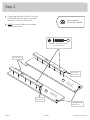
Step 2
å
Fasten two of the SMALL SUPPORTS (X) to the
FOOTBOARD RAILS (N2 and O2). Use twelve
BROWN 1" FLAT HEAD SCREWS (12S).
å
NOTE: Start each SCREW a few turns before
tightening any of them.
414129 www.sauder.com/servicePage 6
N2
O2
X
X
The HIDDEN CAM
must be here.
These holes
must be here.
These holes
must be here.
Finished edge
BROWN 1" FLAT HEAD SCREW
(12 used in this step)
12S
Surface with
HIDDEN CAM
Surface with
HIDDEN CAM
Some assembly
(and snacks) required.

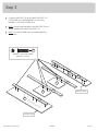
å
Fasten the SUPPORTS (Q) to the LARGE SUPPORTS (Y),
FOOTBOARD (R), and HEADBOARD (S). Use twenty
BROWN 1" FLAT HEAD SCREWS (12S).
å
NOTE: Use the center two holes in the SUPPORTS (Q) that
will be fastened to the LARGE SUPPORTS (Y).
å
NOTE: Start each SCREW a few turns before tightening
any of them.
Step 3
414129www.sauder.com/service
Page 7
Y
R
S
Y
Q
Q
Q
Q
BROWN 1" FLAT HEAD SCREW
(20 used in this step)
12S
Surface with more holes
Unfi nished edge
Unfi nished edge

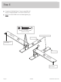
Step 4
å
Fasten the HEADBOARD RAILS (T and U) to the ENDS (A3
and B3). Use eight BROWN 1" FLAT HEAD SCREWS (12S).
å
NOTE: Start each SCREW a few turns before tightening any
of them.
414129 www.sauder.com/servicePage 8
A3
B3
U
T
Surface with
HIDDEN CAM
Surface with
HIDDEN CAM
The HIDDEN CAM
must be here.
The HIDDEN CAM
must be here.
Curved edge
Surface with more holes
Curved edge
BROWN 1" FLAT HEAD SCREW
(8 used in this step)
12S
12S

å
Fasten the remaining two SMALL SUPPORTS (X) to the
HEADBOARD RAILS (T and U). Use twelve BROWN 1"
FLAT HEAD SCREWS (12S).
å
NOTE: Start each SCREW a few turns before tightening
any of them.
Step 5
414129www.sauder.com/service
Page 9
U
T
X
X
BROWN 1" FLAT HEAD SCREW
(12 used in this step)
12S
These holes
must be here.
These holes
must be here.

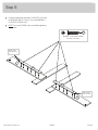
Step 6
å
Peel the FELT DISCS from the FELT DISC CARDS (1M)
and stick them onto the edges of the ENDS (A3 and B3),
LARGE SUPPORTS (Y), and FOOTBOARD (R) as shown.
414129 www.sauder.com/servicePage 10
Y
R
Y
A3
B3
1M
1M
Long fi nished edge

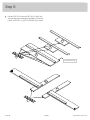
å
Fasten the FOOTBOARD (R) to the FOOTBOARD
RAILS (N2 and O2). Use four BLACK 1-15/16" FLAT
HEAD SCREWS (113S).
å
NOTE: Start each SCREW a few turns before
tightening any of them.
Step 7
414129www.sauder.com/service
Page 11
N2
O2
X
X
R
Q
Finished edge
Finished edge
Long fi nished edge
BLACK 1-15/16" FLAT HEAD SCREW
(4 used in this step)
113S

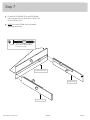
Step 8
å
NOTE: You will need to hold the SUPPORT (Q) o the ground or
place packing material under the SUPPORT while fastening it to
the SMALL SUPPORTS (X).
å
Fasten one of the SUPPORTS (Q) with LARGE SUPPORT (Y) to the
SMALL SUPPORTS (X) on the FOOTBOARD RAILS (N2 and O2).
Use four BLACK 1-15/16" FLAT HEAD SCREWS (113S).
å
NOTE: The LARGE SUPPORT (Y) should be o the ground and
facing toward the FOOTBOARD (R).
414129 www.sauder.com/servicePage 12
Don't worry. It isn't
Rome. This can be built
in a day.
Y
N2
O2
X
X
Q
R
BLACK 1-15/16" FLAT HEAD SCREW
(4 used in this step)
113S

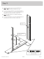
å
NOTE: Do not apply any pressure to the SUPPORT (Q) or
HEADBOARD (S) once they are fastened in this step.
å
Fasten the remaining SUPPORT (Q) with LARGE SUPPORT (Y)
to the SMALL SUPPORT (X) on the LEFT HEADBOARD RAIL (T).
Use two BLACK 1-15/16" FLAT HEAD SCREWS (113S).
å
NOTE: The LARGE SUPPORT (Y) should be facing toward
the HEADBOARD (S).
å
Fasten the HEADBOARD (S) to the LEFT HEADBOARD RAIL (T).
Use two BLACK 1-15/16" FLAT HEAD SCREWS (113S).
Step 9
414129www.sauder.com/service
Page 13
BLACK 1-15/16" FLAT HEAD SCREW
(4 used in this step)
113S
S
Q
Y
Q
Finished edge
with holes
T
X
The LARGE SUPPORT (Y)
should be here.
B3

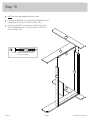
Step 10
å
NOTE: You may need someone's help in this step.
å
Fasten the HEADBOARD (S) to the RIGHT HEADBOARD RAIL (U).
Use two BLACK 1-15/16" FLAT HEAD SCREWS (113S).
å
Fasten the SUPPORT (Q) to the SMALL SUPPORT (X) on the
RIGHT HEADBOARD RAIL (U). Use two BLACK 1-15/16" FLAT
HEAD SCREWS (113S).
414129 www.sauder.com/servicePage 14
A3
U
Q
BLACK 1-15/16" FLAT HEAD SCREW
(4 used in this step)
113S
X
B3
S

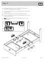
å
With someone's help, carefully turn the FOOTBOARD (R) assembly and the
HEADBOARD (S) assembly onto their bottom edges.
å
Insert two BI-CAM DOWELS (25F) into the HEADBOARD RAILS (T and U). Tighten
two HIDDEN CAMS.
å
Insert two WOOD DOWELS (15F) into the HEADBOARD RAILS (T and U).
å
Fasten the FOOTBOARD RAILS (N2 and O2) to the HEADBOARD RAILS (T and U).
Tighten two HIDDEN CAMS.
å
NOTE: Be sure the WOOD DOWELS in the HEADBOARD RAILS insert into the
FOOTBOARD RAILS.
Step 11
414129www.sauder.com/service
Page 15
U
T
N2
O2
15F
25F
15F
25F
1
2
R
S

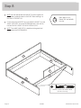
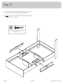
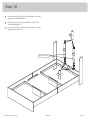
Step 12
å
Fasten the Z-PLATES (75G) to the RAILS (N2, O2, T, and U).
Use eight BLACK 9/16" LARGE HEAD SCREWS (1S).
å
NOTE: The Z-PLATES will wrap around the bottom edges of
the RAILS (N2, O2, T, and U).
414129 www.sauder.com/servicePage 16
U
T
N2
O2
BLACK 9/16" LARGE HEAD SCREW
(8 used in this step)
1S
75G
75G

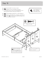
å
Insert four METAL PINS (1R) into the holes in the top
edge of the HEADBOARD (S).
å
Place the SLATS (I3) onto the METAL PINS (1R) in
the HEADBOARD (S).
å
Insert four METAL PINS (1R) into the holes in the top
edges of the SLATS (I3).
Step 13
414129www.sauder.com/service
Page 17
S
I3
I3
Finished surface
1R
1R

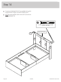
Step 14
å
Fasten the HEADBOARD TOP (E3) to the ENDS (A3 and B3).
Use four BLACK 1-15/16" FLAT HEAD SCREWS (113S).
å
NOTE: Be sure the METAL PINS in the SLATS (I3) insert into
the HEADBOARD TOP.
414129 www.sauder.com/servicePage 18
I3
I3
A3
B3 E3
BLACK 1-15/16" FLAT HEAD SCREW
(4 used in this step)
113S
Finished surface
113S
Edge without holes

å
NOTE: Position the BACKS (V) exactly as shown.
å
Fasten the BACKS (V and Z) to the ENDS (A3 and B3),
HEADBOARD TOP (E3), SLATS (I3), and HEADBOARD (S). Use
twenty-eight BLACK 9/16" LARGE HEAD SCREWS (1S).
å
NOTE: The outside edges of the BACKS (V) will be fastened last.
å
NOTE: There are no pre-drilled holes in the edges of the ENDS (A3
and B3). Use fi rm pressure when fastening the outside edges of the
BACKS (V) to the ENDS (A3 and B3).
Step 15
414129www.sauder.com/service
Page 19
A tracking label will be on this
surface of one of the BACKS (V).
Please do not remove.
If you're doing this to
help a friend, don't
leave without a bite.
A3
B3
E3
Z
S
BLACK 9/16" LARGE HEAD SCREW
(28 used in this step)
1S
Unfi nished
surface
V
Unfi nished
surface
V
Unfi nished
surface
I3
NOTE: Fasten the outside edges
of the BACKS (V) last using fi rm
pressure. The two smaller holes in
the edges of the BACKS (V) must
line up over the ENDS (A3 and B3).

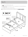
Step 16
å
NOTE: Position the PLATFORMS (W) exactly as shown.
å
Fasten the PLATFORMS (W) to the SUPPORTS (Q, X, and Y). Use sixteen BLACK 1-1/2" FLAT HEAD SCREWS (101S) into
the exact holes shown.
å
This completes assembly. Clean with a damp cloth. Wipe dry.
414129 www.sauder.com/servicePage 20
BLACK 1-1/2" FLAT HEAD SCREW
(16 used in this step)
101S
W
W
W
These holes are
closer together
and must be here.
These holes are
closer together
and must be here.
NOTE: Do not
put SCREWS into
these two holes.
Y
Q
X
And to celebrate, why not share your success story at Walmart.com or
La page charge ...
La page charge ...
La page charge ...
La page charge ...
La page charge ...
La page charge ...
La page charge ...
La page charge ...
-
 1
1
-
 2
2
-
 3
3
-
 4
4
-
 5
5
-
 6
6
-
 7
7
-
 8
8
-
 9
9
-
 10
10
-
 11
11
-
 12
12
-
 13
13
-
 14
14
-
 15
15
-
 16
16
-
 17
17
-
 18
18
-
 19
19
-
 20
20
-
 21
21
-
 22
22
-
 23
23
-
 24
24
-
 25
25
-
 26
26
-
 27
27
-
 28
28


Sauder 414129 Assembly Instruction Manual
- Taper
- Assembly Instruction Manual
dans d''autres langues
- English: Sauder 414129
- español: Sauder 414129
Documents connexes
-
Sauder Mates Bed 423003 Mode d'emploi
-
-
-
-
-
-
-
-
-