Miller ME000000V Le manuel du propriétaire
- Catégorie
- Système de soudage
- Taper
- Le manuel du propriétaire
Ce manuel convient également à

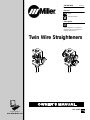
Twin Wire Straighteners
Process
Submerged Arc Welding
(SAW)
OM-264 500A 2014−09
Description
Wire Straighteners For Automated
Welding Using The Submerged Arc
Welding (SAW) Process
Automatic Welding
Visit our website at
www.MillerWelds.com
File: (SAW)

Miller Electric manufactures a full line
of welders and welding related equipment.
For information on other quality Miller
products, contact your local Miller distributor to receive the latest full
line catalog or individual specification sheets. To locate your nearest
distributor or service agency call 1-800-4-A-Miller, or visit us at
www.MillerWelds.com on the web.
Thank you and congratulations on choosing Miller. Now you can get
the job done and get it done right. We know you don’t have time to do
it any other way.
That’s why when Niels Miller first started building arc welders in 1929,
he made sure his products offered long-lasting value and superior
quality. Like you, his customers couldn’t afford anything less. Miller
products had to be more than the best they could be. They had to be the
best you could buy.
Today, the people that build and sell Miller products continue the
tradition. They’re just as committed to providing equipment and service
that meets the high standards of quality and value established in 1929.
This Owner’s Manual is designed to help you get the most out of your
Miller products. Please take time to read the Safety precautions. They
will help you protect yourself against potential hazards on the worksite.
We’ve made installation and operation quick
and easy. With Miller you can count on years
of reliable service with proper maintenance.
And if for some reason the unit needs repair,
there’s a Troubleshooting section that will
help you figure out what the problem is. The
parts list will then help you to decide the
exact part you may need to fix the problem.
Warranty and service information for your
particular model are also provided.
Miller is the first welding
equipment manufacturer in
the U.S.A. to be registered to
the ISO 9001 Quality System
Standard.
Working as hard as you do
− every power source from
Miller is backed by the most
hassle-free warranty in the
business.
From Miller to You
Mil_Thank 2009−09

TABLE OF CONTENTS
SECTION 1 −SAFETY PRECAUTIONS FOR GMAW WELDING GUNS − READ BEFORE USING 1......
1-1. Symbol Usage 1.......................................................................
1-2. Arc Welding Hazards 1.................................................................
1-3. Proposition 65 Warnings 2...............................................................
1-4. Principal Safety Standards 2.............................................................
1-5. EMF Information 2.....................................................................
SECTION 2 − MESURES DE SÉCURITÉ VISANT LES PISTOLETS DE SOUDAGE GMAW −
À LIRE AVANT UTILISATION 3.....................................................
2-1. Signification des symboles 3.............................................................
2-2. Dangers relatifs au soudage à l’arc 3......................................................
2-3. Proposition californienne 65 Avertissements 4..............................................
2-4. Principales normes de sécurité 4.........................................................
2-5. Informations relatives aux CEM 4.........................................................
SECTION 3 − SPECIFICATIONS 7..............................................................
3-1. Welding Torches 7.....................................................................
3-2. Overall Dimensions 7...................................................................
SECTION 4 − INSTALLATION 8................................................................
4-1. Installing Wire Straightener Into Drive Assembly 8...........................................
4-2. Wire Straightener − Twin Wire Single Adjust 9..............................................
4-3. Twin Wire - Double/Separate Adjustment Wire Straightener 10.................................
SECTION 5 − MAINTENANCE AND TROUBLESHOOTING 11.......................................
5-1. SubArc Interface Analog Routine Maintenance 11............................................
5-2. Troubleshooting Table 11.................................................................
SECTION 6 − PARTS LIST 12...................................................................
WARRANTY


OM-264 500 Page 1
SECTION 1 −SAFETY PRECAUTIONS FOR GMAW
WELDING GUNS − READ BEFORE USING
SR7 (MIG) 2013-09
Protect yourself and others from injury — read, follow, and save these important safety precautions and operating instructions.
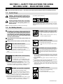
1-1. Symbol Usage
DANGER! − Indicates a hazardous situation which, if
not avoided, will result in death or serious injury. The
possible hazards are shown in the adjoining symbols
or explained in the text.
Indicates a hazardous situation which, if not avoided,
could result in death or serious injury. The possible
hazards are shown in the adjoining symbols or ex-
plained in the text.
NOTICE − Indicates statements not related to personal injury.
Indicates special instructions.
This group of symbols means Warning! Watch Out! ELECTRIC
SHOCK, MOVING PARTS, and HOT PARTS hazards. Consult sym-
bols and related instructions below for necessary actions to avoid the
hazards.
1-2. Arc Welding Hazards
The symbols shown below are used throughout this manual
to call attention to and identify possible hazards. When you
see the symbol, watch out, and follow the related instructions
to avoid the hazard. The safety information given below is
only a summary of the more complete safety information
found in the welding power source Owner’s Manual. Read
and follow all Safety Standards.
Only qualified persons should install, operate, maintain, and
repair this unit.
During operation, keep everybody, especially children, away.
ELECTRIC SHOCK can kill.
Always wear dry insulating gloves.
Insulate yourself from work and ground.
Do not touch live electrode or electrical parts.
Replace worn, damaged, or cracked guns or cables.
Turn off welding power source before changing contact tip or gun
parts.
Keep all covers and handle securely in place.
FUMES AND GASES can be hazardous.
Keep your head out of the fumes.
Ventilate area, or use breathing device. The
recommended way to determine adequate
ventilation is to sample for the composition and quantity of fumes
and gases to which personnel are exposed.
Read and understand the Safety Data Sheets (SDSs) and the
manufacturer’s instructions for adhesives, coatings, cleaners,
consumables, coolants, degreasers, fluxes, and metals.
WELDING can cause fire or explosion.
Do not weld near flammable material.
Do not weld on containers that have held com-
bustibles, or on closed containers such as
tanks, drums, or pipes unless they are properly prepared ac-
cording to AWS F4.1 and AWS A6.0 (see Safety Standards).
Watch for fire; keep extinguisher nearby.
Read and understand the Safety Data Sheets (SDSs) and the
manufacturer’s instructions for adhesives, coatings, cleaners,
consumables, coolants, degreasers, fluxes, and metals.
BUILDUP OF GAS can injure or kill.
Shut off compressed gas supply when not in
use.
Always ventilate confined spaces or use ap-
proved air-supplied respirator.
MOVING PARTS can injure.
Keep away from moving parts.
Keep away from pinch points such as drive
rolls.
Arc rays from the welding process produce intense
visible and invisible (ultraviolet and infrared) rays
that can burn eyes and skin. Sparks fly off from the
weld.
ARC RAYS can burn eyes and skin.
Wear an approved welding helmet fitted with a proper shade of filter
lenses to protect your face and eyes from arc rays and sparks
when welding or watching (see ANSI Z49.1 and Z87.1 listed in
Safety Standards).
Wear approved safety glasses with side shields under your
helmet.
Use protective screens or barriers to protect others from flash,
glare and sparks; warn others not to watch the arc.
Wear body protection made from durable, flame-resistant material
(leather, heavy cotton, wool). Body protection includes oil-free
clothing such as leather gloves, heavy shirt, cuffless trousers, high
shoes, and a cap.
HOT PARTS can burn.
Allow gun to cool before touching.
Do not touch hot metal.
Protect hot metal from contact by others.

OM-264 500 Page 2
NOISE can damage hearing.
Noise from some processes or equipment can
damage hearing.
Check for noise level limits exceeding those
specified by OSHA.
Use approved ear plugs or ear muffs if noise level is high.
Warn others nearby about noise hazard.
WELDING WIRE can injure.
Keep hands and body away from gun tip when
trigger is pressed.
READ INSTRUCTIONS.
Read and follow all labels and the Owner’s
Manual carefully before installing, operating, or
servicing unit. Read the safety information at
the beginning of the manual and in each
section.
Use only genuine replacement parts from the manufacturer.
Perform maintenance and service according to the Owner’s
Manuals, industry standards, and national, state, and local
codes.
1-3. Proposition 65 Warnings
Welding or cutting equipment produces fumes or gases
which contain chemicals known to the State of California to
cause birth defects and, in some cases, cancer. (California
Health & Safety Code Section 25249.5 et seq.)
This product contains chemicals, including lead, known to
the state of California to cause cancer, birth defects, or other
reproductive harm. Wash hands after use.
1-4. Principal Safety Standards
Safety in Welding, Cutting, and Allied Processes, ANSI Standard Z49.1,
is available as a free download from the American Welding Society at
http://www.aws.org or purchased from Global Engineering Documents
(phone: 1-877-413-5184, website: www.global.ihs.com).
Safe Practice For Occupational And Educational Eye And Face Protec-
tion, ANSI Standard Z87.1, from American National Standards Institute,
25 West 43rd Street, New York, NY 10036 (phone: 212-642-4900, web-
site: www.ansi.org).
Safe Practices for the Preparation of Containers and Piping for Welding
and Cutting, American Welding Society Standard AWS F4.1, from Glob-
al Engineering Documents (phone: 1-877-413-5184, website: www.glo-
bal.ihs.com).
Safe Practices for Welding and Cutting Containers that have Held Com-
bustibles, American Welding Society Standard AWS A6.0, from Global
Engineering Documents (phone: 1-877-413-5184,
website: www.global.ihs.com).
National Electrical Code, NFPA Standard 70, from National Fire Protec-
tion Association, Quincy, MA 02269 (phone: 1-800-344-3555, website:
www.nfpa.org and www. sparky.org).
Safe Handling of Compressed Gases in Cylinders, CGA Pamphlet P-1,
from Compressed Gas Association, 14501 George Carter Way, Suite
103, Chantilly, VA 20151 (phone: 703-788-2700, website:
www.cganet.com).
Safety in Welding, Cutting, and Allied Processes, CSA Standard
W117.2, from Canadian Standards Association, Standards Sales, 5060
Spectrum Way, Suite 100, Ontario, Canada L4W 5NS (phone:
800-463-6727, website: www.csa-international.org).
Safe Practice For Occupational And Educational Eye And Face Protec-
tion, ANSI Standard Z87.1, from American National Standards Institute,
25 West 43rd Street, New York, NY 10036 (phone: 212-642-4900, web-
site: www.ansi.org).
Standard for Fire Prevention During Welding, Cutting, and Other Hot
Work, NFPA Standard 51B, from National Fire Protection Association,
Quincy, MA 02269 (phone: 1-800-344-3555, website: www.nfpa.org.
OSHA, Occupational Safety and Health Standards for General Indus-
try, Title 29, Code of Federal Regulations (CFR), Part 1910, Subpart Q,
and Part 1926, Subpart J, from U.S. Government Printing Office, Super-
intendent of Documents, P.O. Box 371954, Pittsburgh, PA 15250-7954
(phone: 1-866-512-1800) (there are 10 OSHA Regional Offices—
phone for Region 5, Chicago, is 312-353-2220, website:
www.osha.gov).
1-5. EMF Information
Electric current flowing through any conductor causes localized electric
and magnetic fields (EMF). The current from arc welding (and allied pro-
cesses including spot welding, gouging, plasma arc cutting, and induc-
tion heating operations) creates an EMF field around the welding circuit.
EMF fields may interfere with some medical implants, e.g. pacemakers.
Protective measures for persons wearing medical implants have to be
taken. For example, restrict access for passers−by or conduct individu-
al risk assessment for welders. All welders should use the following pro-
cedures in order to minimize exposure to EMF fields from the welding
circuit:
1. Keep cables close together by twisting or taping them, or using a
cable cover.
2. Do not place your body between welding cables. Arrange cables
to one side and away from the operator.
3. Do not coil or drape cables around your body.
4. Keep head and trunk as far away from the equipment in the
welding circuit as possible.
5. Connect work clamp to workpiece as close to the weld as
possible.
6. Do not work next to, sit or lean on the welding power source.
7. Do not weld whilst carrying the welding power source or wire
feeder.
About Implanted Medical Devices:
Implanted Medical Device wearers should consult their doctor and the
device manufacturer before performing or going near arc welding, spot
welding, gouging, plasma arc cutting, or induction heating operations.
If cleared by your doctor, then following the above procedures is recom-
mended.

OM-246 500 Page 3
SECTION 2 − MESURES DE SÉCURITÉ VISANT LES
PISTOLETS DE SOUDAGE GMAW − À LIRE AVANT
UTILISATION
SR7(MIG)_2013−09 fre
Pour écarter les risques de blessure pour vous−même et pour autrui — lire, appliquer et ranger en lieu sûr ces consignes relatives
aux précautions de sécurité et au mode opératoire.
2-1. Signification des symboles
DANGER! − Indique une situation dangereuse qui si on
l’évite pas peut donner la mort ou des blessures graves.
Les dangers possibles sont montrés par les symboles
joints ou sont expliqués dans le texte.
Indique une situation dangereuse qui si on l’évite pas
peut donner la mort ou des blessures graves. Les dan-
gers possibles sont montrés par les symboles joints ou
sont expliqués dans le texte.
NOTE − Indique des déclarations pas en relation avec des blessures
personnelles.
Indique des instructions spécifiques.
Ce groupe de symboles veut dire Avertissement! Attention! DANGER
DE CHOC ELECTRIQUE, PIECES EN MOUVEMENT, et PIECES
CHAUDES. Consulter les symboles et les instructions ci-dessous y
afférant pour les actions nécessaires afin d’éviter le danger.
2-2. Dangers relatifs au soudage à l’arc
Les symboles présentés ci-après sont utilisés tout au long du
présent manuel pour attirer votre attention et identifier les ris-
ques de danger. Lorsque vous voyez un symbole, soyez vigi-
lant et suivez les directives mentionnées afin d’éviter tout
danger. Les consignes de sécurité présentées ci-après ne
font que résumer l’information contenue dans les normes de
sécurité énumérées dans le manuel d’utilisation du poste de
soudage. Veuillez lire et respecter toutes ces normes de sé-
curité.
L’installation, l’utilisation, l’entretien et les réparations ne
doivent être confiés qu’à des personnes qualifiées.
Au cours de l’utilisation, tenir toute personne à l’écart et plus
particulièrement les enfants.
UN CHOC ÉLECTRIQUE peut tuer.
Porter toujours des gants secs et isolants.
S’isoler de la pièce et de la terre.
Ne jamais toucher une électrode ou des pièces
électriques sous tension.
Remplacer les pistolets ou câbles de soudage qui sont endom-
magés, usés ou craquelés.
Mettre la soudeuse hors tension avant de remplacer un bec con-
tact ou des pièces de pistolet.
S’assurer que tous les couvercles et poignées sont fermement
assujettis.
LES VAPEURS ET LES FUMÉES
peuvent être nocives.
Éloigner sa tête des endroits renfermant des
vapeurs.
Aérer la zone de travail ou porter un appareil re-
spiratoire. Pour déterminer la bonne ventila-
tion, il est recommandé de procéder à un
prélèvement pour la composition et la quantité
de fumées et de gaz auxquels est exposé le
personnel.
Lire et comprendre les fiches de données de sécurité et les instruc-
tions du fabricant concernant les adhésifs, les revêtements, les
nettoyants, les consommables, les produits de refroidissement, les
dégraisseurs, les flux et les métaux.
LE SOUDAGE peut causer un incen-
die ou une explosion.
Ne pas souder à proximité de matériaux inflam-
mables.
Ne pas effectuer le soudage sur des conteneurs fermés tels que
des réservoirs, tambours, ou conduites, à moins qu’ils n’aient été
préparés correctement conformément à AWS F4.1 et AWS A6.0
(voir les Normes de Sécurité).
Prendre garde aux incendies et toujours avoir un extincteur à
proximité.
Lire et comprendre les fiches de données de sécurité et les
instructions du fabricant concernant les adhésifs, les revêtements,
les nettoyants, les consommables, les produits de refroidissement,
les dégraisseurs, les flux et les métaux.
L’ACCUMULATION DE VAPEURS
peut causer des lésions ou la mort.
Quand on n’utilise pas le gaz comprimé de
protection, fermer le robinet de la bouteille.
Assurer toujours la ventilation des zones fer-
mées ou utiliser un appareil respiratoire avec
alimentation en air.
Les PIÈCES MOBILES peuvent
causer des blessures.
Ne pas s’approcher des organes mobiles.
Ne pas s’approcher des points de coincement
tels que des rouleaux de commande.
LE RAYONNEMENT DE L’ARC peut
brûler les yeux et la peau.
Le rayonnement de l’arc du procédé de soudage
génère des rayons visibles et invisibles intenses
(ultraviolets et infrarouges) susceptibles de provoquer des brûlures
dans les yeux et sur la peau. Des étincelles sont projetées pendant le
soudage.
Porter un casque de soudage approuvé muni de verres filtrants
approprié pour protéger visage et yeux pendant le soudage
(voir ANSI Z49.1 et Z87.1 énuméré dans les normes de sécurité).
Porter des lunettes de sécurité avec écrans latéraux même sous
votre casque.

OM-246 500 Page 4
Avoir recours à des écrans protecteurs ou à des rideaux pour
protéger les autres contre les rayonnements les éblouissements
et les étincelles ; prévenir toute personne sur les lieux de ne pas
regarder l’arc.
Porter un équipement de protection pour le corps fait d’un matériau
résistant et ignifuge (cuir, coton robuste, laine). La protection du
corps comporte des vêtements sans huile comme par ex. des
gants de cuir, une chemise solide, des pantalons sans revers, des
chaussures hautes et une casquette.
LES PIÈCES CHAUDES peuvent
provoquer des brûlures.
Laisser refroidir le pistolet avant de le toucher.
Ne pas toucher d’objets métalliques chauds.
Abriter les objets métalliques contre tout con-
tact par les personnes à proximité.
Le BRUIT peut endommager l’ouie.
Le bruit des processus et des équipements peut
affecter l’ouïe.
Vérifier si les niveaux de bruit excèdent les lim-
ites spécifiées par l’OSHA.
Utiliser des bouche-oreilles ou des serre-tête antibruit approuvés si
le niveau de bruit est élevé.
Avertir les personnes à proximité au sujet du danger inhérent au
bruit.
LES FILS DE SOUDAGE peuvent
provoquer des blessures.
Éloigner les mains et le corps de la buse du pis-
tolet après avoir appuyé sur la gâchette.
LIRE LES INSTRUCTIONS.
Lire et appliquer les instructions sur les
étiquettes et le Mode d’emploi avant
l’installation, l’utilisation ou l’entretien de
l’appareil. Lire les informations de sécurité au
début du manuel et dans chaque section.
N’utiliser que les pièces de rechange recommandées par le cons-
tructeur.
Effectuer l’entretien en respectant les manuels d’utilisation,
les normes industrielles et les codes nationaux, d’état et locaux.
2-3. Proposition californienne 65 Avertissements
Les équipements de soudage et de coupage produisent des
fumées et des gaz qui contiennent des produits chimiques
dont l’État de Californie reconnaît qu’ils provoquent des
malformations congénitales et, dans certains cas, des
cancers. (Code de santé et de sécurité de Californie, chapitre
25249.5 et suivants)
Ce produit contient des éléments chimiques, dont le plomb,
reconnus par l’État de Californie pour leur caractère
cancérogène ainsi que provoquant des malformations
congénitales ou autres problèmes de procréation. Se laver
les mains après toute manipulation.
2-4. Principales normes de sécurité
Safety in Welding, Cutting, and Allied Processes, ANSI Standard Z49.1,
is available as a free download from the American Welding Society at
http://www.aws.org or purchased from Global Engineering Documents
(phone: 1-877-413-5184, website: www.global.ihs.com).
Safe Practice For Occupational And Educational Eye And Face Protec-
tion, ANSI Standard Z87.1, from American National Standards Institute,
25 West 43rd Street, New York, NY 10036 (phone: 212-642-4900, web-
site: www.ansi.org).
Safe Practices for the Preparation of Containers and Piping for Welding
and Cutting, American Welding Society Standard AWS F4.1, from Glob-
al Engineering Documents (phone: 1-877-413-5184, website: www.glo-
bal.ihs.com).
Safe Practices for Welding and Cutting Containers that have Held Com-
bustibles, American Welding Society Standard AWS A6.0, from Global
Engineering Documents (phone: 1-877-413-5184,
website: www.global.ihs.com).
National Electrical Code, NFPA Standard 70, from National Fire Protec-
tion Association, Quincy, MA 02269 (phone: 1-800-344-3555, website:
www.nfpa.org and www. sparky.org).
Safe Handling of Compressed Gases in Cylinders, CGA Pamphlet P-1,
from Compressed Gas Association, 14501 George Carter Way, Suite
103, Chantilly, VA 20151 (phone: 703-788-2700, website:
www.cganet.com).
Safety in Welding, Cutting, and Allied Processes, CSA Standard
W117.2, from Canadian Standards Association, Standards Sales, 5060
Spectrum Way, Suite 100, Ontario, Canada L4W 5NS (phone:
800-463-6727, website: www.csa-international.org).
Safe Practice For Occupational And Educational Eye And Face Protec-
tion, ANSI Standard Z87.1, from American National Standards Institute,
25 West 43rd Street, New York, NY 10036 (phone: 212-642-4900, web-
site: www.ansi.org).
Standard for Fire Prevention During Welding, Cutting, and Other Hot
Work, NFPA Standard 51B, from National Fire Protection Association,
Quincy, MA 02269 (phone: 1-800-344-3555, website: www.nfpa.org.
OSHA, Occupational Safety and Health Standards for General Indus-
try, Title 29, Code of Federal Regulations (CFR), Part 1910, Subpart Q,
and Part 1926, Subpart J, from U.S. Government Printing Office, Super-
intendent of Documents, P.O. Box 371954, Pittsburgh, PA 15250-7954
(phone: 1-866-512-1800) (there are 10 OSHA Regional Offices—
phone for Region 5, Chicago, is 312-353-2220, website:
www.osha.gov).
2-5. Informations relatives aux CEM
Le courant électrique qui traverse tout conducteur génère des champs
électromagnétiques (CEM) à certains endroits. Le courant de soudage
crée un CEM autour du circuit et du matériel de soudage. Le courant
issu d’un soudage à l’arc (et de procédés connexes, y compris le
soudage par points, le gougeage, le découpage plasma et les
opérations de chauffage par induction) crée un champ
électromagnétique (CEM) autour du circuit de soudage. Des mesures
de protection pour les porteurs d’implants médicaux doivent être prises:
Limiter par exemple tout accès aux passants ou procéder à une
évaluation des risques individuels pour les soudeurs. Tous les
soudeurs doivent appliquer les procédures suivantes pour minimiser
l’exposition aux CEM provenant du circuit de soudage:
1 Rassembler les câbles en les torsadant ou en les attachant avec
du ruban adhésif ou avec une housse.
2 Ne pas se tenir au milieu des câbles de soudage. Disposer les
câbles d’un côté et à distance de l’opérateur.
3 Ne pas courber et ne pas entourer les câbles autour de votre
corps.

OM-246 500 Page 5
4 Maintenir la tête et le torse aussi loin que possible du matériel du
circuit de soudage.
5 Connecter la pince sur la pièce aussi près que possible de la
soudure.
6 Ne pas travailler à proximité d’une source de soudage, ni
s’asseoir ou se pencher dessus.
7 Ne pas souder tout en portant la source de soudage ou le
dévidoir.
En ce qui concerne les implants médicaux :
Les porteurs d’implants doivent d’abord consulter leur médecin avant
de s’approcher des opérations de soudage à l’arc, de soudage par
points, de gougeage, du coupage plasma ou de chauffage par induc-
tion. Si le médecin approuve, il est recommandé de suivre les procédu-
res précédentes.

OM-246 500 Page 6

OM-264 500 Page 7
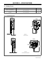
SECTION 3 − SPECIFICATIONS
3-1. Welding Torches
Model Wire Diameter Capacity Net Weight
Twin Wire - Single Adjustment
3/64, 1/16, 5/64, 3/32 in.
(1.2, 1.6, 2.0, 2.4 mm)
2.78 lb
(1.26 kg)
Twin Wire - Double/Separate
Adjustment
3/64, 1/16, 5/64, 3/32 in.
(1.2, 1.6, 2.0, 2.4 mm)
4.17 lb
(1.89 kg)
9561721179_2-A
3-2. Overall Dimensions
47/64 in.
(19 mm)
1-31/64 in.
(38 mm)
2.15 in.
(55 mm)
2-9/16 in.
(65 mm)
8-1/32 in.
(204 mm)
4-9/32 in.
(109 mm)
Twin Wire
Single Adjustment
Twin Wire
Double Separate Adjustment
2-9/16 in.
(65 mm)
47/64 in.
(19 mm)
1-31/64 in.
(38 mm)
5-9/32 in.
(134 mm)
4-21/32 in.
(118 mm)
8-1/32 in.
(204 mm)
2-51/64 in.
(70 mm)

OM-264 500 Page 8
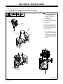
SECTION 4 − INSTALLATION
For complete installation into wire drive assembly, see wire drive Owner’s Manual.
4
-1. Installing Wire Straightener Into Drive Assembly
9561721189_3-A
! Turn Off welding power
source and weld control be-
fore starting installation..
1 Wire Drive Assembly (Not
Included)
2 Wire Straightener
Wire Straightener is used to re-
move bends and irregularities from
welding wire.
3 Alignment Plate
Allows for correct alignment of the
wire straightener and drive assem-
bly to aid in smooth wire feeding.
Install wire straightener into drive
assembly as shown.
Push welding wire thru guide
up to drive roll, continue to hold
welding sire. Press Inch Down
button until drive rolls grab
wire. Adjust tension until wires
do not slip. Indicator is for refer-
ence only.
−
3
2
1

OM-264 500 Page 9
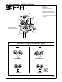
4-2. Wire Straightener − Twin Wire Single Adjust
956172119_5A
Suitable Applications For Twin Wire − Single Adjustment Wire Straightener
Wire
Straightener
Spools With Same
Level Of Wire
Spools With Different
Levels Of Wire
Less Wire
Unbalanced
Spools Can
Cause Wire
Feeding
Problems
More Wire
1 Rollers
2 Inlet Guide
3 Guide Securing Screws
Secure guide with screws.
4 Wire Pressure Adjustment Knob
5 Alignment Plate (See Section 4-1)
When using this straightener, make
sure spools have an equal amount
of wire to ensure wires straighten
properly .
Roller Direction When
Knob Is Rotated Clockwise
3
5
4
3
2
1
YES NO
Wire
Straightener

OM-264 500 Page 10
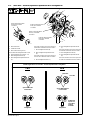
4-3. Twin Wire - Double/Separate Adjustment Wire Straightener
11
12
Roller (D) Direction When
Knob (D) Is Rotated
Clockwise
1
2
3
3
6
4
3
9
Roller (B) Direction When
Knob (B) Is Rotated
Clockwise
Roller (A) Direction When
Knob (A) Is Rotated
Clockwise
Roller (C) Direction When
Knob (C) Is Rotated
Clockwise
5
7
8
10
956172119_7-A
Suitable Applications For Twin Wire − Double Adjustment Wire Straightener
Unbalanced
Spools Can
Cause Wire
Feeding
Problems
Less Wire
More Wire
1 Wire Inlet Guide
2 Outlet Wire Guide
3 Wire Guide Securing Screw
Secure inlet and outlet guides with screws.
4 Alignment Plate (See Section 4-1)
5 Wire Straightener Roller (A)
6 Wire Straightener Adjustment Knob
(A)
Turn knob clockwise to increase pressure
on both wires in direction shown on roller A.
7 Wire Straightener Roller (B)
8 Wire Straightener Adjustment Knob
(B)
Turn knob clockwise to increase pressure
on inner wire in direction shown on roller B.
9 Wire Straightener Roller (C)
10 Wire Straightener Adjustment Knob
(C)
Turn knob clockwise to increase pressure
on both wires in direction shown on roller C.
11 Wire Straightener Roller (D)
12 Wire Straightener Adjustment Knob
(D)
Turn knob clockwise to increase pressure
on outer wire in direction shown on roller D.
YES
Spools With Same
Level Of Wire
Wire
Straightener
Wire
Straightener
Spools With Different
Levels Of Wire
YES

OM-264 500 Page 11
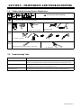
SECTION 5 − MAINTENANCE AND TROUBLESHOOTING
5-1. SubArc Interface Analog Routine Maintenance
! Disconnect power before maintaining.
= Check = Change = Clean Δ = Repair = Replace
* To be done by Factory Authorized Service Agent
Every
3
Months
Weld Terminals
Labels Nozzle Contact Tip
Every
3
Months
Δ Cables And Cords
Every
6
Months
:During heavy service, clean monthly.
Drive Rolls
Blow out liner.
5-2. Troubleshooting Table
Trouble Remedy
Wire does not feed. Check contact tip. Check for kinks in outlet cable. Check connections at wire drive assembly. Have
nearest Factory Authorized Service Agent check automatic equipment and welding power source.
Wire is not energized. Check contact tip. Check connections at wire drive assembly. Have nearest Factory Authorized Ser-
vice Agent check automatic equipment and welding power source.
Wire feeds unevenly. Check contact tip. Check for kinks in outlet cable. Blow out gun liner and outlet cable casing.

OM-264 500 Page 12
SECTION 6 − PARTS LIST
956172119_9-A
Hardware is common and
not available unless listed.
8
7
13
6
5
5
4
3
8
8
7
13
6
8
7
13
6
5
8
5
4
16
1
8
11
10
8
14
9
15
12
5
5
42
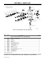
Figure 6-1. Wire Straightener, Twin, Single Adjustment
Description
Part
No.
Item
No.
Figure 6-1. Wire Straightener, Twin, Single Adjustment
Quantity
1 266717 Housing Wire Straightener 1.. .... .. ...................................................
2 266735 Spring 1.. .... .. ....................................................................
3 266718 Roll Carrier 1.. .... .. ................................................................
4 266719 Spacer 3.. .... .. ....................................................................
5 *266721 Ball Bearing 6.. ... .. ...............................................................
6 *266736 Roll, Twin Wire Rectifier 3.. ... .. ....................................................
7 266722 Spring washer D. 8.1 mm 3.. .... .. ....................................................
8 266723 Screw, Hex M8x30 7.. .... .. .........................................................
9 266720 Friction Washer 1.. .... .. ............................................................
10 266726 Retaining Ring, 6mm 1. ... .. ........................................................
11 266725 Knob 1. ... .. ......................................................................
12 *266734 Wire Guide, Outlet 1. .. .. ..........................................................
13 266730 Internal Retaining Ring D. 22 mm 3. ... .. ............................................
14 266737 Top Alignment Plate 1. ... .. ........................................................
15 266738 Screw M6x12 1. ... .. ..............................................................
16 *266733 Wire Guide, Inlet 1. .. .. ...........................................................
*Recommended spare part.
To maintain the factory original performance of your equipment, use only Manufacturer’s Suggested
Replacement Parts. The Model Number is required when ordering parts from your distributor.

OM-264 500 Page 13
956172119_11-A
Hardware is common and
not available unless listed.
8
7
13
6
5
5
10
11
8
3
2
24
1
8
4
5
17
13
18
16
9
11
10
10
11
9
22
23
20
13
5
17
19
14
12
8
22
8
3
2
4
5
5
13
6
7
8
9
4
15
2
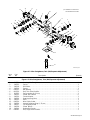
Figure 6-2. Wire Straightener, Twin (Dbl/Separate Adjustment)
Description
Part
No.
Item
No.
Figure 6-2. Wire Straightener, Twin (Dbl/Separate Adjustment)
Quantity
1 266739 Housing Wire Straightener 1.. .... .... .................................................
2 266735 Spring 3.. .... .... ...................................................................
3 266718 Roll carrier 2.. .... .... ..............................................................
4 266719 Spacer 3.. .... .... ..................................................................
5 *266721 Ball Bearing 6.. ... .... .............................................................
6 *266736 Roll, Twin Wire Rectifier 2.. ... .... ..................................................
7 266722 Spring washer D. 8.1 mm 2.. ... .... .................................................
8 266723 Screw, Hex M8x30 6.. .... .... ......................................................
9 266720 Friction Washer 3.. .... .... ..........................................................
10 266726 Retaining Ring, 6mm 3. ... .... ......................................................
11 266725 Knob 3. ... .... ....................................................................
12 *266734 Wire Guide, Outlet 1. .. .... ........................................................
13 266730 Internal Retaining Ring D. 22 mm 4. ... .... ..........................................
14 266737 Top Alignment Plate 1. ... .... .......................................................
15 266738 Screw M6x12 1. ... .... ............................................................
16 266740 Double Roll Carrier 1. ... .... ........................................................
17 *266741 Roll, Single Wire Rectifier 2. .. .... .................................................

OM-264 500 Page 14
Description
Part
No.
Item
No.
Figure 6-2. Wire Straightener,Twin (Dbl/Separate Adjustment) (continued)
Quantity
18 266742 Screw, Wire Straightener 1. ... .... ..................................................
19 266743 Slide 1. ... .... ....................................................................
20 266744 External Retaining Ring D. 8 mm 1. ... .... ...........................................
21 266745 Second Wire Regulation Pin 1. ... .... ................................................
22 266746 Knob 1. ... .... ....................................................................
23 266747 Dowel M4x5 2. ... .... .............................................................
24 *266733 Wire Guide, Inlet 1. .. .... ..........................................................
*Recommended spare part.
To maintain the factory original performance of your equipment, use only Manufacturer’s Suggested
Replacement Parts. The Model Number is required when ordering parts from your distributor.

Effective January 1, 2014
(Equipment with a serial number preface of ME or newer)
This limited warranty supersedes all previous Miller warranties and is exclusive with no other
guarantees or warranties expressed or implied.
LIMITED WARRANTY − Subject to the terms and conditions below,
Miller Electric Mfg. Co., Appleton, Wisconsin, warrants to its original
retail purchaser that new Miller equipment sold after the effective
date of this limited warranty is free of defects in material and
workmanship at the time it is shipped by Miller. THIS WARRANTY IS
EXPRESSLY IN LIEU OF ALL OTHER WARRANTIES, EXPRESS
OR IMPLIED, INCLUDING THE WARRANTIES OF
MERCHANTABILITY AND FITNESS.
Within the warranty periods listed below, Miller will repair or replace
any warranted parts or components that fail due to such defects in
material or workmanship. Miller must be notified in writing within
thirty (30) days of such defect or failure, at which time Miller will
provide instructions on the warranty claim procedures to be
followed.
Miller shall honor warranty claims on warranted equipment listed
below in the event of such a failure within the warranty time periods.
All warranty time periods start on the delivery date of the equipment
to the original end-user purchaser, and not to exceed twelve months
after the equipment is shipped to a North American distributor or
eighteen months after the equipment is shipped to an International
distributor.
1. 5 Years Parts — 3 Years Labor
* Original Main Power Rectifiers Only to Include SCRs,
Diodes, and Discrete Rectifier Modules
2. 3 Years — Parts and Labor
* Auto-Darkening Helmet Lenses (Except Classic
Series) (No Labor)
* Engine Driven Welding Generators
(NOTE: Engines are Warranted Separately by the
Engine Manufacturer.)
* Inverter Power Sources (Unless Otherwise Stated)
* Plasma Arc Cutting Power Sources
* Process Controllers
* Semi-Automatic and Automatic Wire Feeders
* Transformer/Rectifier Power Sources
3. 2 Years — Parts and Labor
* Auto-Darkening Helmet Lenses − Classic Series Only
(No Labor)
* Fume Extractors − Capture 5, Filtair 400 and Industrial
Collector Series
4. 1 Year — Parts and Labor Unless Specified
* Automatic Motion Devices
* CoolBelt and CoolBand Blower Unit (No Labor)
* External Monitoring Equipment and Sensors
* Field Options
(NOTE: Field options are covered for the remaining
warranty period of the product they are installed in, or
for a minimum of one year — whichever is greater.)
* RFCS Foot Controls (Except RFCS-RJ45)
* Fume Extractors − Filtair 130, MWX and SWX Series
* HF Units
* ICE/XT Plasma Cutting Torches (No Labor)
* Induction Heating Power Sources, Coolers
(NOTE: Digital Recorders are Warranted Separately
by the Manufacturer.)
* LiveArc Welding Performance Management System
* Load Banks
* Motor Driven Guns (except Spoolmate Spoolguns)
* PAPR Blower Unit (No Labor)
* Positioners and Controllers
* Racks
* Running Gear/Trailers
* Spot Welders
* Subarc Wire Drive Assemblies
* Water Coolant Systems
* TIG Torches (No Labor)
* Wireless Remote Foot/Hand Controls and Receivers
* Work Stations/Weld Tables (No Labor)
5. 6 Months — Parts
* Batteries
* Bernard Guns (No Labor)
* Tregaskiss Guns (No Labor)
6. 90 Days — Parts
* Accessory (Kits)
* Canvas Covers
* Induction Heating Coils and Blankets, Cables, and
Non-Electronic Controls
* M-Guns
* MIG Guns and Subarc (SAW) Guns
* Remote Controls and RFCS-RJ45
* Replacement Parts (No labor)
* Roughneck Guns
* Spoolmate Spoolguns
Miller’s True Blue® Limited Warranty shall not apply to:
1. Consumable components; such as contact tips,
cutting nozzles, contactors, brushes, relays, work
station table tops and welding curtains, or parts that
fail due to normal wear. (Exception: brushes and
relays are covered on all engine-driven products.)
2. Items furnished by Miller, but manufactured by others,
such as engines or trade accessories. These items are
covered by the manufacturer’s warranty, if any.
3. Equipment that has been modified by any party other than
Miller, or equipment that has been improperly installed,
improperly operated or misused based upon industry
standards, or equipment which has not had reasonable
and necessary maintenance, or equipment which has
been used for operation outside of the specifications for
the equipment.
MILLER PRODUCTS ARE INTENDED FOR PURCHASE AND
USE BY COMMERCIAL/INDUSTRIAL USERS AND PERSONS
TRAINED AND EXPERIENCED IN THE USE AND
MAINTENANCE OF WELDING EQUIPMENT.
In the event of a warranty claim covered by this warranty, the
exclusive remedies shall be, at Miller’s option: (1) repair; or (2)
replacement; or, where authorized in writing by Miller in appropriate
cases, (3) the reasonable cost of repair or replacement at an
authorized Miller service station; or (4) payment of or credit for the
purchase price (less reasonable depreciation based upon actual
use) upon return of the goods at customer’s risk and expense.
Miller’s option of repair or replacement will be F.O.B., Factory at
Appleton, Wisconsin, or F.O.B. at a Miller authorized service facility
as determined by Miller. Therefore no compensation or
reimbursement for transportation costs of any kind will be allowed.
TO THE EXTENT PERMITTED BY LAW, THE REMEDIES
PROVIDED HEREIN ARE THE SOLE AND EXCLUSIVE
REMEDIES. IN NO EVENT SHALL MILLER BE LIABLE FOR
DIRECT, INDIRECT, SPECIAL, INCIDENTAL OR
CONSEQUENTIAL DAMAGES (INCLUDING LOSS OF PROFIT),
WHETHER BASED ON CONTRACT, TORT OR ANY OTHER
LEGAL THEORY.
ANY EXPRESS WARRANTY NOT PROVIDED HEREIN AND ANY
IMPLIED WARRANTY, GUARANTY OR REPRESENTATION AS
TO PERFORMANCE, AND ANY REMEDY FOR BREACH OF
CONTRACT TORT OR ANY OTHER LEGAL THEORY WHICH,
BUT FOR THIS PROVISION, MIGHT ARISE BY IMPLICATION,
OPERATION OF LAW, CUSTOM OF TRADE OR COURSE OF
DEALING, INCLUDING ANY IMPLIED WARRANTY OF
MERCHANTABILITY OR FITNESS FOR PARTICULAR
PURPOSE, WITH RESPECT TO ANY AND ALL EQUIPMENT
FURNISHED BY MILLER IS EXCLUDED AND DISCLAIMED BY
MILLER.
Some states in the U.S.A. do not allow limitations of how long an
implied warranty lasts, or the exclusion of incidental, indirect,
special or consequential damages, so the above limitation or
exclusion may not apply to you. This warranty provides specific
legal rights, and other rights may be available, but may vary from
state to state.
In Canada, legislation in some provinces provides for certain
additional warranties or remedies other than as stated herein, and to
the extent that they may not be waived, the limitations and
exclusions set out above may not apply. This Limited Warranty
provides specific legal rights, and other rights may be available, but
may vary from province to province.
Warranty Questions?
Call
1-800-4-A-MILLER
for your local
Miller distributor.
miller_warr 2014-04-14
Your distributor also gives
you ...
Service
You always get the fast,
reliable response you
need. Most replacement
parts can be in your
hands in 24 hours.
Support
Need fast answers to the
tough welding questions?
Contact your distributor.
The expertise of the
distributor and Miller is
there to help you, every
step of the way.

ORIGINAL INSTRUCTIONS − PRINTED IN USA © 2014 Miller Electric Mfg. Co. 2014−01
Miller Electric Mfg. Co.
An Illinois Tool Works Company
1635 West Spencer Street
Appleton, WI 54914 USA
International Headquarters−USA
USA Phone: 920-735-4505 Auto-Attended
USA & Canada FAX: 920-735-4134
International FAX: 920-735-4125
For International Locations Visit
www.MillerWelds.com
Model Name Serial/Style Number
Purchase Date (Date which equipment was delivered to original customer.)
Distributor
Address
City
State Zip
Please complete and retain with your personal records.
Always provide Model Name and Serial/Style Number.
Contact a DISTRIBUTOR or SERVICE AGENCY near you.
Welding Supplies and Consumables
Options and Accessories
Personal Safety Equipment
Service and Repair
Replacement Parts
Training (Schools, Videos, Books)
Technical Manuals (Servicing Information
and Parts)
Circuit Diagrams
Welding Process Handbooks
Contact the Delivering Carrier to:
For Service
Owner’s Record
File a claim for loss or damage during
shipment.
For assistance in filing or settling claims, contact
your distributor and/or equipment manufacturer’s
Transportation Department.
Contact your Distributor for:
To locate a Distributor or Service Agency visit
www.millerwelds.com or call 1-800-4-A-Miller
-
 1
1
-
 2
2
-
 3
3
-
 4
4
-
 5
5
-
 6
6
-
 7
7
-
 8
8
-
 9
9
-
 10
10
-
 11
11
-
 12
12
-
 13
13
-
 14
14
-
 15
15
-
 16
16
-
 17
17
-
 18
18
-
 19
19
-
 20
20


Miller ME000000V Le manuel du propriétaire
- Catégorie
- Système de soudage
- Taper
- Le manuel du propriétaire
- Ce manuel convient également à
dans d''autres langues
- English: Miller ME000000V Owner's manual
Documents connexes
-
Miller MF510108T Le manuel du propriétaire
-
-
-
-
-
-
-
-
-