Miller LIVEARC WELDING PERFORMANCE MANAGEMENT SYSTEM Le manuel du propriétaire
- Catégorie
- Système de soudage
- Taper
- Le manuel du propriétaire
Ce manuel convient également à

LiveArc
Welding Performance Management System
Processes
Description
™
MIG (GMAW) Welding
Arc Welding Training System
OM-267 357A 2014−07
Visit our website at
www.MillerWelds.com
File: Accessory

Miller Electric manufactures a full line
of welders and welding related equipment.
For information on other quality Miller
products, contact your local Miller distributor to receive the latest full
line catalog or individual specification sheets. To locate your nearest
distributor or service agency call 1-800-4-A-Miller, or visit us at
www.MillerWelds.com on the web.
Thank you and congratulations on choosing Miller. Now you can get
the job done and get it done right. We know you don’t have time to do
it any other way.
That’s why when Niels Miller first started building arc welders in 1929,
he made sure his products offered long-lasting value and superior
quality. Like you, his customers couldn’t afford anything less. Miller
products had to be more than the best they could be. They had to be the
best you could buy.
Today, the people that build and sell Miller products continue the
tradition. They’re just as committed to providing equipment and service
that meets the high standards of quality and value established in 1929.
This Owner’s Manual is designed to help you get the most out of your
Miller products. Please take time to read the Safety precautions. They
will help you protect yourself against potential hazards on the worksite.
We’ve made installation and operation quick
and easy. With Miller you can count on years
of reliable service with proper maintenance.
And if for some reason the unit needs repair,
there’s a Troubleshooting section that will
help you figure out what the problem is. The
parts list will then help you to decide the
exact part you may need to fix the problem.
Warranty and service information for your
particular model are also provided.
Miller is the first welding
equipment manufacturer in
the U.S.A. to be registered to
the ISO 9001 Quality System
Standard.
Working as hard as you do
− every power source from
Miller is backed by the most
hassle-free warranty in the
business.
From Miller to You
Mil_Thank 2009−09

TABLE OF CONTENTS
SECTION 1 − WELDING TABLE SAFETY PRECAUTIONS − READ BEFORE USING 1................
1-1. Symbol Usage 1.......................................................................
1-2. Welding Training System Hazards 1.......................................................
1-3. Proposition 65 Warnings 2...............................................................
1-4. Principal Safety Standards 2.............................................................
SECTION 2 − MESURES DE SÉCURITÉ − TABLE DE SOUDURE − À LIRE AVANT UTILISATION 3....
2-1. Symboles utilisés 3.....................................................................
2-2. Dangers liés au système de formation en soudure 3.........................................
2-3. Proposition californienne 65 Avertissements 4..............................................
2-4. Principales normes de sécurité 4.........................................................
SECTION 3 − DEFINITIONS 5.................................................................
3-1. Miscellaneous Symbols And Definitions 5..................................................
SECTION 4 − SPECIFICATIONS 6.............................................................
4-1. Introduction 6.........................................................................
4-2. Serial Number And Rating Label Location 7................................................
4-3. Specifications 7........................................................................
4-4. Environmental Specifications 7...........................................................
4-5. Naming Convention For Miller Welding Assignments 8.......................................
SECTION 5 − INSTALLATION 9................................................................
5-1. Selecting A Location 9..................................................................
5-2. Tipping 10.............................................................................
5-3. Installing Monitor Stand On Weld Table 10...................................................
5-4. Optional Positioning Arm 11..............................................................
5-5. Optional Extension Arm And Clamp Assembly 12............................................
5-6. Grounding The Work Table 13.............................................................
5-7. Installing Power Source Work Clamp 14....................................................
5-8. Installing Mig SmartGun 15...............................................................
5-9. Making Connections To Touchscreen Monitor 16.............................................
5-10. Connecting Input Power To Monitor 17......................................................
SECTION 6 − SYSTEM CONTROLS AND COMPONENTS 18.......................................
6-1. Touchscreen Monitor Controls 18..........................................................
6-2. Training System Cameras And Markers 19..................................................
6-3. SmartGun Controls 20...................................................................
6-4. Using The Workpiece Calibration Tool 21...................................................
SECTION 7 − OPERATION 22..................................................................
7-1. Equipment Setup 22.....................................................................
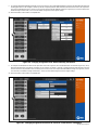
7-2. Getting Started 22.......................................................................
7-2A. Login Screen 22........................................................................
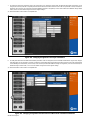
7-2B. Select Assignment 24....................................................................
7-2C. Table Calibration 26.....................................................................
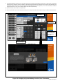
7-2D. Preparing To Weld 28....................................................................
7-2E. Practicing In SIM (Simulation) Mode 31.....................................................
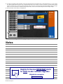
7-2F. Testing In Weld Mode 34.................................................................

TABLE OF CONTENTS
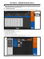
SECTION 8 − ADMINISTRATION TOOLS 36......................................................
8-1. Administration Mode 36..................................................................
8-2. Equipment Settings 36...................................................................
8-3. Software Updates 37....................................................................
8-4. Data Backup And Restoration 37..........................................................
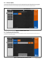
8-5. Gun Calibration 38......................................................................
8-6. Joint Calibration Tool 38..................................................................
8-7. Table Calibration 39.....................................................................
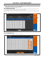
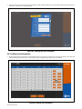
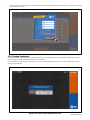
SECTION 9 − ASSIGNMENT MANAGEMENT 40..................................................
9-1. Administration Mode 40..................................................................
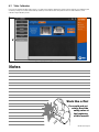
9-2. Creating New Assignments 41............................................................
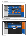
SECTION 10 − USER MANAGEMENT 47........................................................
10-1. Administration Mode 47..................................................................
10-2. Creating New User 47...................................................................
10-3. Editing User Information 48...............................................................
10-4. Viewing Dashboard 49...................................................................
SECTION 11 − MAINTENANCE 50..............................................................
11-1. Routine Maintenance 50.................................................................
11-2. Overload Protection 51..................................................................
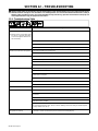
SECTION 12 − TROUBLESHOOTING 52.........................................................
12-1. Troubleshooting Table 52.................................................................
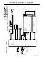
SECTION 13 − ELECTRICAL DIAGRAMS 53......................................................
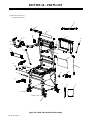
SECTION 14 − PARTS LIST 54..................................................................
SECTION 15 − SOFTWARE LICENSE AGREEMENT 57............................................
WARRANTY

OM-267 357 Page 1
SECTION 1 − WELDING TABLE SAFETY PRECAUTIONS −
READ BEFORE USING
Training System 2014-07
Protect yourself and others from injury — read, follow, and save these important safety precautions and operating instructions.
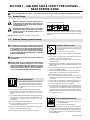
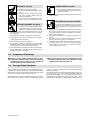
1-1. Symbol Usage
DANGER! − Indicates a hazardous situation which, if
not avoided, will result in death or serious injury. The
possible hazards are shown in the adjoining symbols
or explained in the text.
Indicates a hazardous situation which, if not avoided,
could result in death or serious injury. The possible
hazards are shown in the adjoining symbols or ex-
plained in the text.
NOTICE − Indicates statements not related to personal injury.
Indicates special instructions.
This group of symbols means Warning! Watch Out! ELECTRIC
SHOCK, MOVING PARTS, and HOT PARTS hazards. Consult sym-
bols and related instructions below for necessary actions to avoid the
hazards.
1-2. Welding Training System Hazards
The symbols shown below are used throughout this manual
to call attention to and identify possible hazards. When you
see the symbol, watch out, and follow the related instructions
to avoid the hazard. The safety information given below is
only a summary of the more complete safety information
found in the Safety Standards listed in Section 1-4. Read and
follow all Safety Standards.
Only qualified persons should install, operate, maintain, and
repair this unit.
Welding-related hazards are present when using the welding
training system. Read the welding power source and wire
feeder Owner’s Manuals and labels carefully for more infor-
mation on arc welding hazards. Also read American National
Standard Z49.1, Safety in Welding, Cutting, and Allied Pro-
cesses, from American Welding Society (www.aws.org).
READ INSTRUCTIONS.
Read and follow all labels and the Owner’s
Manual carefully before installing, operating, or
servicing unit. Read the safety information at
the beginning of the manual and in each
section.
Use only genuine replacement parts from the manufacturer.
Perform maintenance and service according to the Owner’s
Manuals, industry standards, and national, state, and local
codes.
Do not repair, modify, or disassemble the training system or use
with parts or accessories not supplied by the manufacturer. Use
only approved components and accessories from the
manufacturer.
Be sure all hardware is properly tightened.
Do not use the training system until you are sure it is correctly
assembled and working properly.
Before each use, inspect the training system for damage and
verify it is secure and installed properly.
Use the training system only as specified in the manual.
ELECTRIC SHOCK can kill.
Touching live electrical parts can cause fatal shocks
or severe burns.
Do not touch live electrical parts.
Disconnect input power before installing or servicing this
equipment.
Do not touch grounded surfaces when using this equipment
(metal pipes, enclosures, structures, etc.).
Keep cords dry, free of oil and grease, and protected from hot
metal and sparks.
Frequently inspect input power cord and ground conductor for
damage or bare wiring – replace immediately if damaged – bare
wiring can kill.
Turn off all equipment when not in use. Do not leave equipment
until it has completely stopped.
Use only well-maintained equipment. Repair or replace dam-
aged parts at once. Maintain unit according to the manual.
Keep all panels and covers securely in place.
Do not use the training system during an electrical storm. Turn
off equipment and disconnect input power until risk of lightning
has passed.
Always verify the supply ground − check and be sure that cord
plug is connected to a properly grounded receptacle outlet.
Do not use equipment in damp or wet conditions.
Incorrectly installed or improperly grounded equipment is a
hazard. Properly install, ground, and operate this equipment
according to its Owner’s Manual and national, state, and local
codes. Also read American National Standard Z49.1, Safety in
Welding, Cutting, and Allied Processes, from American Welding
Society (www.aws.org).
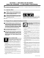
FIRE OR EXPLOSION hazard.
Do not install or place unit on, over, or near
combustible surfaces.
Do not install unit near flammables.
Use the training system only for the recommended application
or the protection provided by the equipment may be impaired. Do
not use the training system table for non-welding operations,
such as painting, sawing wood, or any activity that could produce
flammable materials.

OM-267 357 Page 2
HOT PARTS can burn.
Do not touch hot parts bare handed.
Allow cooling period before working on equip-
ment.
To handle hot parts, use proper tools and/or
wear heavy, insulated welding gloves and
clothing to prevent burns.
Do not remove gloves to operate touch screen.
Touch screen can be activated with gloves on.
FALLING EQUIPMENT can injure.
Do not exceed the maximum weight rating of
welding table, drawers, or shelves (see Spe-
cifications). Spread weight evenly on welding
table, and in drawers and shelves. Do not use
the welding table, tray, drawers, or shelves to stand on or support
heavy equipment.
Use equipment of adequate capacity to lift and support unit.
If using lift forks to move unit, be sure forks are long enough to
extend beyond opposite side of unit.
Do not use powered equipment to drag unit.
Do not move or install training system where it could tip. Install
the training system on a firm, level surface and away from flam-
mable materials. Lock wheels to keep table in position.
Follow the guidelines in the Applications Manual for the Revised
NIOSH Lifting Equation (Publication No. 94−110) when manu-
ally lifting heavy parts or equipment.
MOVING PARTS can injure.
Keep people away from touch screen protec-
tive cover when it is being opened. Keep cover
closed when welding.
Keep people away from optional positioning arm when it is being
raised or lowered.
Arc rays from the welding process produce intense
visible and invisible (ultraviolet and infrared) rays
that can burn eyes and skin. Sparks fly off from the
weld.
Wear an approved welding helmet fitted with a proper shade of
filter lenses to protect your face and eyes from arc rays and
sparks when welding or watching (see ANSI Z49.1 and Z87.1
listed in Safety Standards).
Wear approved safety glasses with side shields under your
helmet.
Use protective screens or barriers to protect others from flash,
glare and sparks; warn others not to watch the arc.
Wear body protection made from durable, flame−resistant mate-
rial (leather, heavy cotton, wool). Body protection includes
oil-free clothing such as leather gloves, heavy shirt, cuffless
trousers, high shoes, and a cap.
ARC RAYS can burn eyes and skin.
1-3. Proposition 65 Warnings
Welding or cutting equipment produces fumes or gases
which contain chemicals known to the State of California to
cause birth defects and, in some cases, cancer. (California
Health & Safety Code Section 25249.5 et seq.)
This product contains chemicals, including lead, known to
the state of California to cause cancer, birth defects, or other
reproductive harm. Wash hands after use.
1-4. Principal Safety Standards
Safety in Welding, Cutting, and Allied Processes, ANSI Standard Z49.1,
is available as a free download from the American Welding Society at
http://www.aws.org or purchased from Global Engineering Documents
(phone: 1-877-413-5184, website: www.global.ihs.com).
Applications Manual for the Revised NIOSH Lifting Equation, The Na-
tional Institute for Occupational Safety and Health (NIOSH), 1600
Clifton Rd, Atlanta, GA 30333 (phone: 1-800-232-4636, website:
www.cdc.gov/NIOSH).
Safety Requirements for Electrical Equipment for Measurement, Con-
trol, and Laboratory Use — Part 1: General requirements, CAN/CSA
Standard C22.2 No. 61010−1−12, from Canadian Standards Associa-
tion, Standards Sales, 5060 Spectrum Way, Suite 100, Ontario, Canada
L4W 5NS (phone: 800-463-6727, website: www.csa-international.org).

OM-267 357 Page 3
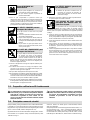
SECTION 2 − MESURES DE SÉCURITÉ −
TABLE DE SOUDURE − À LIRE AVANT UTILISATION
Training System 2014-03_fre
Pour écarter les risques de blessure pour vous−même et pour autrui — lire, appliquer et ranger en lieu sûr ces consignes relatives
aux précautions de sécurité et au mode opératoire.
2-1. Symboles utilisés
DANGER! − Indique une situation dangereuse qui si on
l’évite pas peut donner la mort ou des blessures graves.
Les dangers possibles sont montrés par les symboles
joints ou sont expliqués dans le texte.
Indique une situation dangereuse qui si on l’évite pas
peut donner la mort ou des blessures graves. Les dan-
gers possibles sont montrés par les symboles joints ou
sont expliqués dans le texte.
NOTE − Indique des déclarations pas en relation avec des blessures
personnelles.
Indique des instructions spécifiques.
Ce groupe de symboles veut dire Avertissement! Attention! DANGER
DE CHOC ELECTRIQUE, PIECES EN MOUVEMENT, et PIECES
CHAUDES. Consulter les symboles et les instructions ci-dessous y
afférant pour les actions nécessaires afin d’éviter le danger.
2-2. Dangers liés au système de formation en soudure
Les symboles représentés ci-dessous sont utilisés dans ce ma-
nuel pour attirer l’attention et identifier les dangers possibles. En
présence de l’un de ces symboles, prendre garde et suivre les
instructions afférentes pour éviter tout risque. Les instructions
en matière de sécurité indiquées ci-dessous ne constituent
qu’un sommaire des instructions de sécurité plus complètes
fournies dans les normes de sécurité énumérées dans la Sec-
tion 2-4. Lire et observer toutes les normes de sécurité.
Seul un personnel qualifié est autorisé à installer, faire fonc-
tionner, entretenir et réparer cet appareil.
Welding-related hazards are present when using the welding
training system. Read the welding power source and wire fee-
der Owner’s Manuals and labels carefully for more
information on arc welding hazards. Also read American
National Standard Z49.1, Safety in Welding, Cutting, and
Allied Processes, from American Welding Society
(www.aws.org).
LIRE LES INSTRUCTIONS.
Lire et appliquer les instructions sur les
étiquettes et le Mode d’emploi avan
t
l’installation, l’utilisation ou l’entretien de
l’appareil. Lire les informations de sécurité au
début du manuel et dans chaque section.
N’utiliser que les pièces de rechange recommandées par le
constructeur.
Effectuer l’entretien en respectant les manuels d’utilisation, les
normes industrielles et les codes nationaux, d’état et locaux.
Ne pas réparer, modifier ou démonter le système de formation, e
t
ne pas l’utiliser avec des pièces ou accessoires non fournis par le
fabricant. Utiliser uniquement des composants et accessoires
approuvés par le fabricant.
S’assurer que toute la quincaillerie est bien serrée.
Ne pas utiliser le système de formation avant d’être certain qu’i
l
est bien monté et qu’il fonctionne correctement.
Avant chaque utilisation, inspecter le système de formation pou
r
déceler tout signe de dommage et s’assurer qu’il est bien installé
et maintenu correctement.
Utiliser le système de formation seulement conformément au
manuel.
UNE DÉCHARGE ÉLECTRIQUE peu
t
entraîner la mort.
Tout contact avec des pièces électriques sous
tension peut causer un choc mortel ou des brûlures
graves.
Ne pas toucher aux pièces électriques sous
tension.
Couper le courant avant d’installer ou de faire l’entretien de cet
équipement.
Ne pas toucher à des surfaces mises à la terre pendant
l’utilisation de cet équipement (tuyaux, enceintes, structures et
autres pièces métalliques).
En effectuant les raccordements d’entrée, fixer d’abord le
conducteur de mise à la terre approprié et contre-vérifier les
connexions.
Les câbles doivent être exempts d’humidité, d’huile et de
graisse; protégez−les contre les étincelles et les pièces
métalliques chaudes.
L’équipement doit être hors tension lorsqu’il n’est pas utilisé. Ne
pas laisser l’équipement tant qu’il n’est pas en arrêt complet.
N’utiliser qu’un matériel en bon état. Réparer ou remplacer
sur-le-champ les pièces endommagées. Entretenir l’appareil
conformément à ce manuel.
Maintenir solidement en place tous les panneaux latéraux et les
capots.
Ne pas utiliser le système de formation pendant un orage
électrique. Mettre l’équipement hors tension et débrancher
l’alimentation électrique jusqu’à ce que soit éliminé le risque
d’éclairs.
Toujours vérifier la terre du cordon d’alimentation − Vérifier et
s’assurer que la fiche du cordon est raccordée à une prise
correctement mise à la terre.
Ne pas utiliser l’équipement en conditions humides ou
mouillées.
Des matériels mal installés ou mal mis à la terre présentent un
danger. Installer, mettre à la terre et utiliser correctement cet
appareil, conformément à son manuel d’utilisation et aux codes
nationaux, provinciaux et municipaux. Lire également la norme
Z49.1 de l’American National Standard Institute (ANSI), Safety
in Welding, Cutting, and Allied Processes, (Règles de sécurité
en soudage, coupage et procédés connexes) de l’American
Welding Society (www.aws.org).

OM-267 357 Page 4
Risque D’INCENDIE OU
D’EXPLOSION.
Ne pas placer l’appareil sur, au-dessus ou
à proximité de surfaces inflammables.
Ne pas installer l’appareil à proximité de
produits inflammables.
Pour ne pas compromettre la protection fournie par
l’équipement, utiliser uniquement le système de formation pour
ce dont il est conçu. Ne pas utiliser la table du système de
formation pour des tâches qui ne sont pas liées à la soudure,
comme la peinture, la coupe du bois ou toute autre activité qui
pourrait produire des matières inflammables.
LES PIÈCES CHAUDES peuvent
provoquer des brûlures.
Ne pas toucher à mains nues les parties
chaudes.
Prévoir une période de refroidissement avant
de travailler à l’équipement.
Ne pas toucher aux pièces chaudes, utiliser les
outils recommandés et porter des gants de
soudage et des vêtements épais pour éviter les
brûlures.
Ne pas retirer les gants pour utiliser l’écran
tactile. L’écran tactile peut être activé, même
avec le port de gants.
LA CHUTE DE L’ÉQUIPEMENT peut
provoquer des blessures.
Ne pas dépasser les limites de poids de la table
de soudure, des tiroirs ou des étagères
(se reporter à la fiche technique). Distribuer le
poids de manière uniforme sur la table de
soudure, dans les tiroirs et sur les étagères. Ne pas utiliser la
table de soudure, le plateau, les tiroirs ou les étagères pour
soutenir de l’équipement lourd.
Utiliser un équipement de levage de capacité suffisante pour
lever l’appareil.
En utilisant des fourches de levage pour déplacer l’unité,
s’assurer que les fourches sont suffisamment longues pour
dépasser du côté opposé de l’appareil.
Ne pas utiliser d’équipement motorisé pour tirer l’unité.
Ne pas déplacer ou installer le système de formation à un endroit
où il pourrait se renverser. Installer le système de formation sur
une surface ferme et de niveau, loin des matières inflammables.
Verrouiller les roues pour maintenir la table en position.
Suivre les consignes du Manuel des applications pour l’équation
de levage NIOSH révisée (publication nº94−110) lors du levage
manuel de pièces ou équipements lourds.
Les PIÈCES MOBILES peuvent cau-
ser des blessures.
Maintenir les personnes à distance lors de
l’ouverture du couvercle de protection de
l’écran tactile. Maintenir le couvercle fermé
pendant le soudage.
Maintenir les personnes à distance du bras de positionnement
en option lorsqu’il est soulevé ou abaissé.
LES RAYONS DE L’ARC peuven
t
provoquer des brûlures dans les
yeux et sur la peau.
Le rayonnement de l’arc du procédé de souda
ge
génère des rayons visibles et invisibles intens
es
(ultraviolets et infrarouges) susceptibles de provoquer des brûlu
res
dans les yeux et sur la peau. Des étincelles sont projetées pendan
t le
soudage.
Porter un casque de soudage approuvé muni de verres filtran
ts
approprié pour protéger visage et yeux pour protéger votre visa
ge
et vos yeux pendant le soudage ou pour regarder (voir ANSI Z49
.1
et Z87.1 énuméré dans les normes de sécurité).
Porter des lunettes de sécurité avec écrans latéraux même so
us
votre casque.
Avoir recours à des écrans protecteurs ou à des rideaux po
ur
protéger les autres contre les rayonnements les éblouissements
et
les étincelles ; prévenir toute personne sur les lieux de ne p
as
regarder l’arc.
Porter un équipement de protection pour le corps fait d’un matéri
au
résistant et ignifuge (cuir, coton robuste, laine). La protection
du
corps comporte des vêtements sans huile comme par ex. d
es
gants de cuir, une chemise solide, des pantalons sans revers, d
es
chaussures hautes et une casquette.
2-3. Proposition californienne 65 Avertissements
Les équipements de soudage et de coupage produisent des
fumées et des gaz qui contiennent des produits chimiques
dont l’État de Californie reconnaît qu’ils provoquent des
malformations congénitales et, dans certains cas, des
cancers. (Code de santé et de sécurité de Californie, chapitre
25249.5 et suivants)
Ce produit contient des produits chimiques, notamment du
plomb, dont l’État de Californie reconnaît qu’ils provoquent
des cancers, des malformations congénitales ou d’autres
problèmes de procréation. Se laver les mains après
utilisation.
2-4. Principales normes de sécurité
Safety in Welding, Cutting, and Allied Processes, ANSI Standard Z49.1,
is available as a free download from the American Welding Society at
http://www.aws.org or purchased from Global Engineering Documents
(phone: 1-877-413-5184, website: www.global.ihs.com).
Applications Manual for the Revised NIOSH Lifting Equation, The Na-
tional Institute for Occupational Safety and Health (NIOSH), 1600
Clifton Rd, Atlanta, GA 30333 (phone: 1-800-232-4636, website:
www.cdc.gov/NIOSH).
Safety Requirements for Electrical Equipment for Measurement, Con-
trol, and Laboratory Use — Part 1: General requirements, CAN/CSA
Standard C22.2 No. 61010−1−12, from Canadian Standards Associa-
tion, Standards Sales, 5060 Spectrum Way, Suite 100, Ontario, Canada
L4W 5NS (phone: 800-463-6727, website: www.csa-international.org).

OM-267 357 Page 5
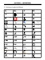
SECTION 3 − DEFINITIONS
3-1. Miscellaneous Symbols And Definitions
A
Amperage
A
L
Aluminum
S
Steel
SS
Stainless Steel
V
Voltage Logout Scroll Forward In
Time
Scroll Back In
Time
IP
Internal Protection
Rating
Unsuccessful Travel Speed Wire Feed
Target Welding Disabled Welding Enabled Panel/Local
(Power Source
Setting)
User Profile FCAW GMAW Assignment
Incomplete
Arrow Left Arrow Right Arrow Up Arrow Down
Assignment
Success Mark
CTWD T-Joint CTWD Butt Joint CTWD Lap Joint
Flare Bevel Weld Fillet Weld Flare Bevel
Groove Weld
Touchscreen
Square Groove
Weld
U-Groove Weld V-Groove Weld Flare V-Groove
Weld
J-Groove Weld Bevel Weld Audio/Sound
GUIDE
Audio Feedback
Input Plug And
Cord
T-Joint Lap Joint Butt Joint
Overhead Position Vertical Position Flat Position Horizontal Position
Work Angle
Butt Joint
Work Angle
T-Joint
Work Angle
Lap Joint
+−
+−
Travel Angle

OM-267 357 Page 6
Aim
Butt Joint
Aim
T-Joint
Aim
Lap Joint
Table Markers
Blocked
Calibration Tool
Marker Blocked
SmartGun LEDs
Blocked
SECTION 4 − SPECIFICATIONS
Welding-related hazards are present when using the welding training system. Read the welding power source and wire feeder Owner’s
Manuals and labels carefully for more information on arc welding hazards. Also read American National Standard Z49.1, Safety in
Welding, Cutting, and Allied Processes, from American Welding Society (www.aws.org). Operators must be trained on the proper use
of this equipment before using the equipment to train others.
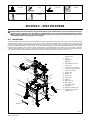
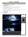
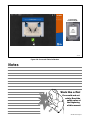
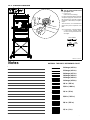
4-1. Introduction
The LiveArc welding training system provides the new student or the experienced welder the opportunity to develop, enhance or verify their welding
abilities through an interactive, simulated or live-arc process on a variety of weld joint configurations. The microprocessor-based training system
connects to nearly any Miller power source/wire feeder combination and uses a series of cameras, LEDs, and markers on the SmartGun and table
to monitor the welds being performed. The user puts on his personal protective equipment, turns on the welding equipment and training system, selects
the desired weld assignment on the touchscreen monitor, and begins either a simulated (practice) or live arc weld. The cameras, markers, and LEDs
convey the weld data (gun angle, gun speed, CTWD, aim) to the system microprocessor which compares it to the specific weld parameters of the
assignment selected. The system evaluates the weld data and grades the student’s performance through a numerical score.
Unit is shown with optional
positioning arm.
1 Caster
2 Tool Drawers
3 Weld Table
4 Table Marker (Sensor) (4)
5 Storage Tray
6 Positioning Arm − Optional
(For Out-Of-Position Welding)
7 Touchscreen Monitor
8 Monitor Cover
9 Speaker (2)
10 Camera (3)
11 Power Cable
12 USB Port
13 Work Clamp (2)
14 MIG SmartGun
(Cables Not Shown)
15 Gun Holder
16 Workpiece Calibration Tool
17 Storage Tray − Workpiece
Calibration Tool
3
1
2
4
5
7
10
8
12
11
9
13
14
15
16
17
268 609-A
6

OM-267 357 Page 7
4-2. Serial Number And Rating Label Location
The serial number and rating information for this product is located on the side of monitor frame. Use rating label to determine input power requirements
and/or rated output, and to register for free software upgrades. For future reference, write serial number in space provided on back cover of this manual.
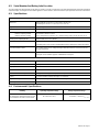
4-3. Specifications
Monitor And Welding Table
Dimensions Table And Monitor: 41-1/2 x 31 x 77-1/2 in. (105 x 79 x197 cm);
w/Positioning Arm: 46 x 31 x 77-1/2 in. (117 x 79 x 197 cm)
Weight (Table/Monitor And Positioning Arm) 407 lb (186 kg)
Input Power 120 Volts AC, 15 Amps, 60 Hz
Operating Conditions:
Maximum Operating Altitude
Maximum Relative Humidity
6562 ft (2000 m) Above Sea Level
80% For Temperatures Up To 88°F (31°C) And Decreasing Linearly To 50% At 104°F (40°C)
Training System Operating Modes Simulated (SIM) And Live Arc (WELD)
Welding Power Source Constant Voltage (CV)
Welding power source must be compliant with IEC60974-1 with regard to reinforced insulation.
Recommended Wire Feeder Any Constant Voltage (CV) Or Voltage Sensing Feeder With Power-Pin Connection And Four−
Pin Trigger Receptacle
Software Version Displayed On Software Updates Screen. See Section 8-3.
Register for free software upgrades at MillerWelds.com/register.
GMAW SmartGun
Processes MIG (GMAW)
Rated Output 400 Amps
Duty Cycle 100%
Standard Wire Sizes .035, .045, .052
Gun Parameters Tracked By Cameras Work Angle, Travel Angle, Travel Speed, Contact Tip To Work Distance (CTWD), Aim
Cooling Air Cooled; SmartGun Displays Message If Gun Overheats
Weight (Gun Only) Gun Only: 3 lb (1.3 kg); Gun With Cable: 11.6 lb (5.3 kg)
Cable Length 15 ft (3.4 m)
4-4. Environmental Specifications
IP Rating Operating Temperature Range Storage Temperature Range
IP21
This equipment is designed for indoor use and
is not intended to be used or stored outside.
32 to 104°F (0 to 40°C)
−25 to 180°F (−31 to 82°C)
IP21 2014−06

OM-267 357 Page 8
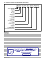
4-5. Naming Convention For Miller Welding Assignments
MATERIAL THICKNESS
Inch Fraction
JOINT TYPE
B=Butt Joint
L=Lap Joint
T=T-Joint
WELD TYPE
F=Fillet
B=Bevel Groove
S=Square Groove
V=V-Groove
WELD POSITION
1=Flat
2=Horizontal
3U=Vertical Uphill
3D=Vertical Down
4=Overhead
BASE MATERIAL TYPE
AL=Aluminum
ST=Steel
SS=Stainless Steel
WELDING PROCESS
G=GMAW
GS=GMAW-S
GP=GMAW-P
FG=FCAW-G
ELECTRODE DIAMETER
Diameter in decimal
WELD PROGRESSION DIRECTION
1/8 BS −Gx−035 (PUSH)−2xST
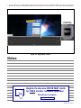
Notes
Register to Receive IMPORTANT Alerts
for FREE LiveArc Software Upgrades
MillerWelds.com/register
Serial Number Sticker

OM-267 357 Page 9
SECTION 5 − INSTALLATION
Welding-related hazards are present when using the welding training system. Read the welding power source and wire feeder Owner’s
Manuals and labels carefully for more information on arc welding hazards. Also read American National Standard Z49.1, Safety in
Welding, Cutting, and Allied Processes, from American Welding Society (www.aws.org). Operators must be trained on the proper use
of this equipment before using the equipment to train others.
! Only qualified persons should in-
stall, operate, maintain, and re-
pair this unit.
! Installation must meet all Nation-
al, State, and Local Codes − have
only qualified persons make this
installation.
! Do not move or operate unit
where it could tip.
! Do not use this equipment to sup-
port personnel, large tools, or
other material.
! Special installation may be re-
quired where gasoline or volatile
liquids are present − see NEC Ar-
ticle 511 or CEC Section 20.
NOTICE − Use training system only in-
doors and away from sources of high fre-
quency (TIG welders) and other types of
electrical interference. It may be neces-
sary to enclose nearby electrical wiring
in conduit if unit is affected by interfer-
ence.
NOTICE − Do not use training system in
damp or wet locations. Keep training
system table and monitor dry.
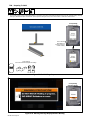
1 Lifting Forks
2 Casters
3 120 Volt, 15 Amp AC Grounded
Receptacle
4 Input Power Cord
Use casters or lifting forks to move unit.
Insert lifting forks beneath bottom shelf
as shown.
If using lifting forks, extend forks beyond
opposite side of unit.
Position unit near the welding equipment
and close to 120 volt AC receptacle but
away from obstructions that may restrict
movement of optional positioning arm.
A 120 volt AC, 15 amp individual
branch circuit protected by time de-
lay fuses or circuit breaker is re-
quired.
268 609-A / 161-046 / 803 053
5-1. Selecting A Location
1
3
2
4
Correct location
for lifting forks.

OM-267 357 Page 10
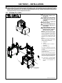
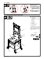
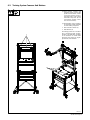
5-2. Tipping
! Do not move or operate unit
where it could tip.
! Do not move unit by pulling
on monitor, struts, or posi-
tioning arm or equipment
may tip. Position lifting forks
beneath table top to move
unit.
! Do not use this equipment to
support personnel, large
tools, or other material.
! Use equipment of adequate
capacity to lift and support
monitor stand.
Stabilize weld table by adjusting
leveling feet.
1 Casters
2 Leveling Foot
3 Monitor Stand
4 Weld Table
5 3/8 x 1-1/2 in. Screw
6 3/8 in. Flat Washer
7 3/8 in. Locknut
Place monitor stand on weld table.
Align holes in base of monitor stand
with holes in weld table. Install four
screws in holes and secure with
washers and locknuts.
5-3. Installing Monitor Stand On Weld Table
7
Tools Needed:
5
6
1
4
3
2
level
9/16 in.
268 609-A

OM-267 357 Page 11
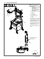
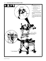
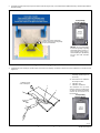
! Keep fingers away from pinch
points on positioning arm.
! Before removing positioning
arm extension:
w Remove weld coupon from
clamp assembly.
w Remove clamp assembly.
w Place clamp assembly in
storage holster.
Stabilize weld table by adjusting
leveling feet.
1 Positioning Arm
2 Clamp Assembly
3 Extension Arm (Section 5-5)
4 Adjustment Lever (Above
Handle)
5 Arm Stop
Use the optional positioning arm to hold
the coupons for horizontal, vertical or
overhead welding at a variety of
heights. The arm accommodates both
right and left-handed welders.
Press lever to release control arm so it
can be raised or lowered. When posi-
tioning arm is not in use, lower arm so
it rests against arm stop.
See Section 5-5 for information on us-
ing the extension arm and clamp as-
sembly.
5-4. Optional Positioning Arm
Tools Needed:
1
2
3
4
5
When positioning arm is not
being used, lower arm so it
rests against stop.
268 609-A

OM-267 357 Page 12
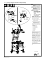
! keep fingers away from
pinch points on position-
ing arm.
! Do not use extension arm
and clamp to support ob-
jects weighing more than
25 lb (11 kg).
! Before removing position-
ing arm extension:
w Remove weld coupon
from clamp assembly.
w Remove clamp as-
sembly.
w Place clamp assembly
in storage holster.
NOTICE − When welding out of
position, position clamp screw on
opposite side of weld coupon to
protect screw from spatter.
Stabilize weld table by ad-
justing leveling feet.
Extension arm and clamp as-
sembly may be installed on
either positioning arm.
Use extension arm and clamp as-
sembly for out-of-position weld
assignments.
1 Extension Arm
2 Locking Bracket
3 Clamp Assembly
4 Safety Pin
5 T-Handle
6 Holster
Slide extension arm into opening
in positioning arm until locking
bracket snaps into place.
Slide clamp assembly shaft
through hole in extension arm and
immediately secure clamp as-
sembly with safety pin. Rotate
clamp assembly to desired posi-
tion and tighten T-handle on ex-
tension arm.
Lower positioning arm and install
weld coupon in clamp. Loosen
clamp T-handle and rotate
coupon to desired position. Tight-
en T−handle. Raise positioning
arm to desired height.
Place extension arm and clamp
assembly in holster when not in
use.
5-5. Optional Extension Arm And Clamp Assembly
Tools Needed:
H
1
2
3
4
5
5
6
Secure clamp
assembly with
safety pin.
268 609-A

OM-267 357 Page 13
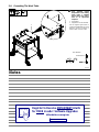
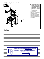
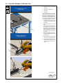
5-6. Grounding The Work Table
! Connect welding table to a
good electrical ground
(independent of the welding
leads) unless a qualified
person assures it is safe to
work on an ungrounded
workpiece.
1 Ground Bolt
2 Tapped Hole For Ground Bolt
Use the supplied ground bolt to
connect the welding table to a good
electrical ground according to
national, state, and local codes.
Tools Needed:
2
Hex Bit 3/16 in.
268 609-A
1
Notes
Register to Receive IMPORTANT Alerts
for FREE LiveArc Software Upgrades
MillerWelds.com/register
Serial Number Sticker

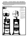
OM-267 357 Page 14
! Keep fingers away from pinch
points on positioning arm.
1 Work Clamp
2 Connection Plate For Weld
Table Work Clamp
3 Work Clamp Connection On
Clamp Assembly
Work clamp plates are located
on both sides of weld table.
Connect work clamp from welding
power source to connection plate on
weld table.
When using optional positioning arm
to perform out-of-position welds,
connect additional work cable from
weld table to flat surface on clamp
assembly.
5-7. Installing Power Source Work Clamp
1
Connect to welding power
source work terminal.
2
3
Connect additional
work cable from weld
table to flat surface on
clamp assembly.
268 609-A
Connect clamp
to flat surface.

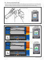
OM-267 357 Page 15
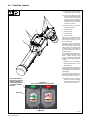
5
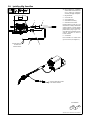
-8. Installing Mig SmartGun
268 609-A / Ref. 245 985-A / Ref. 246 040-A
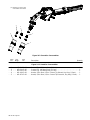
The SmartGun is compatible
with all Miller wire feeders that
use a power pin connection
and four−pin trigger receptacle.
1 Mig SmartGun
2 Gun Power Pin
3 Gun Trigger Plug
4 SmartGun Power Plug
5 SmartGun Power Cable
Install SmartGun power pin and
thread wire according to wire feeder
Owner’s Manual. Connect trigger
plug to feeder. Connect SmartGun
power cable to plug on gun. Con-
nect other end of SmartGun power
cable to receptacle on back of
LiveArc monitor.
6 Gun Holder
Place SmartGun in holder when
gun is not in use (see Figure 4-1).
Tools Needed:
1
2
3
45
Connect other end
of cable to Arc
Station monitor.
Connect other end of cable
to Arc Station monitor.

OM-267 357 Page 16
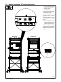
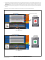
5
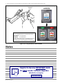
-9. Making Connections To Touchscreen Monitor
1 SmartGun Power Receptacle
2 RJ45 Ethernet Receptacle
3 HDMI Receptacle
4 USB Receptacle
Connect data cable from Smart-
Gun to receptacle on back of moni-
tor. Tighten plug screws.
Use ethernet receptacle to con-
nect training system to a computer
network.
Use HDMI receptacle to connect
training system to an external
monitor.
If the training system is con-
nected to an external monitor,
restart the application to en-
able the monitor. (Section 8).
Use USB receptacle to connect
computer mouse and keyboard,
save test results, and backup and
install software updates (see Sec-
tion 8-3).
123
Monitor Back
C
Monitor Front
4
268 609-A
La page est en cours de chargement...
La page est en cours de chargement...
La page est en cours de chargement...
La page est en cours de chargement...
La page est en cours de chargement...
La page est en cours de chargement...
La page est en cours de chargement...
La page est en cours de chargement...
La page est en cours de chargement...
La page est en cours de chargement...
La page est en cours de chargement...
La page est en cours de chargement...
La page est en cours de chargement...
La page est en cours de chargement...
La page est en cours de chargement...
La page est en cours de chargement...
La page est en cours de chargement...
La page est en cours de chargement...
La page est en cours de chargement...
La page est en cours de chargement...
La page est en cours de chargement...
La page est en cours de chargement...
La page est en cours de chargement...
La page est en cours de chargement...
La page est en cours de chargement...
La page est en cours de chargement...
La page est en cours de chargement...
La page est en cours de chargement...
La page est en cours de chargement...
La page est en cours de chargement...
La page est en cours de chargement...
La page est en cours de chargement...
La page est en cours de chargement...
La page est en cours de chargement...
La page est en cours de chargement...
La page est en cours de chargement...
La page est en cours de chargement...
La page est en cours de chargement...
La page est en cours de chargement...
La page est en cours de chargement...
La page est en cours de chargement...
La page est en cours de chargement...
La page est en cours de chargement...
La page est en cours de chargement...
-
 1
1
-
 2
2
-
 3
3
-
 4
4
-
 5
5
-
 6
6
-
 7
7
-
 8
8
-
 9
9
-
 10
10
-
 11
11
-
 12
12
-
 13
13
-
 14
14
-
 15
15
-
 16
16
-
 17
17
-
 18
18
-
 19
19
-
 20
20
-
 21
21
-
 22
22
-
 23
23
-
 24
24
-
 25
25
-
 26
26
-
 27
27
-
 28
28
-
 29
29
-
 30
30
-
 31
31
-
 32
32
-
 33
33
-
 34
34
-
 35
35
-
 36
36
-
 37
37
-
 38
38
-
 39
39
-
 40
40
-
 41
41
-
 42
42
-
 43
43
-
 44
44
-
 45
45
-
 46
46
-
 47
47
-
 48
48
-
 49
49
-
 50
50
-
 51
51
-
 52
52
-
 53
53
-
 54
54
-
 55
55
-
 56
56
-
 57
57
-
 58
58
-
 59
59
-
 60
60
-
 61
61
-
 62
62
-
 63
63
-
 64
64


Miller LIVEARC WELDING PERFORMANCE MANAGEMENT SYSTEM Le manuel du propriétaire
- Catégorie
- Système de soudage
- Taper
- Le manuel du propriétaire
- Ce manuel convient également à
dans d''autres langues
Documents connexes
-
Miller MF080000D Le manuel du propriétaire
-
-
-
-
-
-
-
-
-