STI 1100 Stopper II Series Pull Station Cover Manuel utilisateur
- Taper
- Manuel utilisateur

- 1 -
Stopper II® SERIES
ADA
Compliant
ADA
Compliant
Photo is a generic representation to reect the many manufacturers of manual pull stations.
· Can be used as a guard against physical damage to manual pull station, with or without
optional warning horn.
· Optional horn has choice of 95 dB or 105 dB (measured at 1 foot).
· Standardredunitshave“InCaseofFire...”labelunlessspeciedwith“nolabel”or
“custom label” (extra charge for custom label).
· Typical working properties of polycarbonate are -40° to 250°F (-40° to 121°C).
· Three year guarantee against breakage of polycarbonate housing in normal use (one year
on electro mechanical and electronic components).
· Weather Stopper models provide a raintight seal to the NEMA 3R standard. (IPX4
equivalency)
We protect the things that protect you.®
®

- 2 -
UL Listed Models Included on this Install Sheet
Indoor Use:
STI-1100 Withhornforushmountedappliances
STI-1100RC Withhornforushmountedappliancesincludesrelaycontactscapableof
operating from 9-24 VDC remote power or internal 9V battery power
STI-1130 With horn and 2” conduit spacer for surface mounted appliances and
electrical boxes
STI-1130RC Surface mounted version of the 1100RC includes 2” conduit spacer
STI-1200 Withouthornforushmountedappliances
STI-1230 Without horn, with 2” conduit spacer for surface mounted appliances and
electrical boxes
Specications
Polycarbonate Enclosure
· Flammability UL94 V-2
· Wall Thickness .095 inches
· NEMA Rating Meets NEMA 3R when mounted to smooth non-masonry surfaces
WARNING: This product can expose you to chemicals including Dichloromethane, which is known
to the State of California to cause cancer, and Bisphenol A (BPA), which is known to the State of
California to cause birth defects or other reproductive harm.
For more information go to www.P65Warnings.ca.gov.
Testing Approvals
It has been tested and approved or listed by:
· UL/cUL Listed
· CertiedADACompliant
· Weather Stopper models provide a raintight seal similar to NEMA 3R when mounted on
smoothatsurface.
· MEA 49-00-E (STI-1200)
· ObtainlocalremarshalapprovalforStateofCalifornia
Indoor/Outdoor Use (Weather Stopper Models)
All outdoor units include necessary gaskets.
STI-1150 Withhornforushmountedappliances
STI-1150RC Withhornforushmountedappliancesincludesrelaycontactscapableof
operating from 9-24 VDC remote power or internal 9V battery power also
includes weather gasket
STI-1155 Surface mounted version of the STI-1150 includes 2” conduit spacer
STI-1155RC Surface mounted version of the STI-1150RC includes 2” conduit spacer
STI-1250 Withouthornforushmountedappliances
STI-3150 Without horn with 2” conduit spacer for surface mounted appliances and
electrical boxes
STI-1102 Replacement horn for cover with alarm
Custom-LBL Custom text message for horn housing
Gaskets
· Closed Cell IV2 with pressure sensitive adhesive
· Replace after 5 years
9V 12V 24V
· Low (95 dB @ 1 ft.) 96mA 107mA 125mA
· High (105 dB @ 1 ft.) 130mA 145mA 182mA
· Min. Operating Req. 2V @ 20mA 4V @ 20mA 4V @ 20mA
Horn
Relay
9V 12V 24V
· Relay 23mA 25mA 29mA
· Min. Activation Voltage 3.7V 5.8V 5.8V
· Reset Voltage 1.5V 3.3V 3.3V
· Dry Contact Rating <30V, 1A <30V, 1A <30V, 1A
(type Form “C”)

- 3 -
Specications (continued)
Temperature Range
· -40° to 120°F (-40° to 49°C)
· For temperatures below -4°F (-20°C) recommend using remote power source
Warranty
· Three year guarantee against breakage of polycarbonate housing in normal use (one year on electro
mechanical and electronic components).
· Electronic warranty form at www.sti-usa.com/wc14.
Important Notice
StopperIIisintendedtobeusedinareaswheretheincidenceoffalserealarmsfrom
manual pull stations is high or has proven to be a serious problem. Any disadvantage of this
deviceismorethanbalancedwhenoneconsiderstheconsequencesoffalserealarms,
especiallyifreservicepersonnelandequipmentarerespondingtoafalserealarmwhen
theyareneededforarealresomewhereelse.Addtothisthedisruptiontothefacilitywhen
falsealarmsoccur.Ifyouhave,ormayhave,aproblemwithfalserealarmsorphysical/
weatherdamagetoyourrealarmactivationdevices,theStopperIIcouldproveinvaluable.
Avis important
Le Stopper II est destiné à être utilisé dans les zones où l’occurrence de fausses alertes d’incendie issues d’avertisseurs
d’incendie manuels est élevée ou présente un problème grave. Un quelconque inconvénient de ce dispositif est vite contrecarré
par les conséquences des fausses alertes d’incendie, surtout lorsque le personnel et l’équipement des services d’incendie
réagissent à une fausse alerte d’incendie alors que leur intervention ailleurs sur un vrai incendie s’avère nécessaire en même
temps. À cela s’ajoute l’agitation éprouvée dans l’établissement au moment du déclenchement d’une fausse alerte. Si vous
rencontrez, ou risquez de rencontrer, un problème avec les fausses alertes d’incendie ou avec l’éventuel endommagement
par effet climatique ou physique de vos dispositifs de déclenchement des alertes d’incendie, le Stopper II pourra alors se
révéler d’une valeur inestimable.
1. When used outdoors, the manual pull station must also be rated for outdoor use.
2. The relay contacts on Model STI-1100RC, STI-1130RC, STI-1150RC and STI-1155RC,
ULListingdoesnotpermitconnectiontorealarmoralifesafetyfunction.
3. According to UL Listing, models powered from an external power source cannot be
suppliedfromtherealarmpanel.
4. When properly installed the operation of this cover will not interfere with the function of
your life safety system.
5. A backplate and gaskets must be used to achieve NEMA 3R integrity.
6. Horn must be tested annually for proper operation. Battery replacement is recommended
annually dependent on use and battery expiration date.
7. If mounting to an uneven surface STI recommends the use of the STI-1280 backplate to
ensure proper sealing. If wire access or screw mounting holes are needed, backplate
may be drilled as necessary.
Installation Notes
1. L’avertisseur d’incendie manuel doit être homologué pour une utilisation à l’extérieur en cas de recours à une telle
utilisation.
2. L’homologation UL des contacts de relais sur les modèles STI-1100RC, STI-1130RC, STI-1150RC et STI-1155RC
n’autorise pas leur connexion à une fonction d’alerte d’incendie ou de sécurité des personnes.
3. Selon l’homologation UL, les modèles alimentés par une source électrique externe ne peuvent pas être intégrés au
panneau d’alerte d’incendie.
4. Lorsqu’il est correctement installé, le fonctionnement de ce couvercle ne provoquera aucune interférence avec le
fonctionnement de votre système de sécurité des personnes.
5. Un palastre et des joints d’étanchéité doivent être utilisés pour atteindre l’intégrité NEMA 3R.
6. L’alarmesonoredoitêtretestéeannuellementpourconrmersonbonfonctionnement.Ilestrecommandéderemplacer
la pile chaque année et ce en fonction du taux d’utilisation et de la validité de la pile.
7. Dans le cas d’un montage sur une surface irrégulière, STI recommande l’utilisation du palastre STI-1280 pour garantir
uneétanchéitéadéquatecontrelasurfacedemontage.S’ilestnécessaired’accéderauxlsouauxtrousdesvisde
montage, le palastre peut être percé tel que requis.
Remarques sur l’installation

- 4 -
Installation Instructions
Fig. 2
FIND CENTER OF
PULL STATION
AND USE GIVEN
DIMENSIONS TO
CENTER PULL STATION
IN VISIBLE OPENING
OF COVER. DRILL
4 HOLES PER STEP 2.
LIFT HERE
I N CASE OF FIRE - LI FT COVER
PULL FI RE ALARM
4.9375 in.
(125mm)
2 in.
(51mm)
3.125 in.
(79mm)
6.25 in.
(159mm)
IF DRILLING INTO MASONRY
OR DRYWALL USE PROVIDED
ANCHORS. DRILL (4) 1/4”
(6.3mm) HOLES 1 1/4” DEEP. IF
DRILLING INTO WOOD, DRILL
(4) 5/32” (3.9mm) HOLES 1 1/4”
DEEP. DO NOT USE ANCHORS
IF DRILLING INTO WOOD.
EXISTING
PULL STATION
BACKPLATE
NOTE: WHEN DRILLING HOLE IN
BACKPLATE NEMA 3R INTEGRITY
IS COMPROMISED
ADHESIVE SIDE
WHEN GASKETS ARE USED, INSTALL
GASKET PROVIDED BY PEELING OFF
BACKING PAPER AND APPLY WITH
ADHESIVE FACING WALL. ALIGN HOLES
IN GASKET WITH HOLES DRILLED AND
STICK ON MOUNTING SURFACE.
OPTIONAL STI-1103
RELAY BOARD
RED +
BLACK –
GREEN NORMALLY OPEN
BLUE COMMON
WHITE NORMALLY CLOSED
3/32 in. ALLEN WRENCH
(NOT PROVIDED)
SWITCH LOCKING SCREW
5 INCHES OF CABLE IS
PROVIDED FOR SERVICE LOOP.
MAKE SURE THIS LOOP AND
ALL OTHER CABLES DO NOT
INTERFERE WITH STATION
OPERATION.
TO LOCK POWER SWITCH IN
THE "OFF" OR "ON" POSITION
TIGHTEN LOCKING SCREW FULLY
UNTIL SCREW MAKES CONTACT
WITH SWITCH PAD AS SHOWN.
OFF
OPTIONAL RELAY CONTACT SETTINGS
STI MODELS 1100RC, 1130RC, 1150RC AND 1155RC
USE ONLY
9 VOLT BATTERY
JUMPER USED ON STANDARD 9
VOLT INTERNALLY
POWERED MODELS
JUMPER INSTALLED ON "RC" MODELS
FOR EXTERNALLY SUPPLIED 12VDC OR
24VDC POWER
NOTE: SMALL CONNECTOR ON JUMPER
FITS INTO PLUG ON RELAY BOARD
THIS JUMPER IS INCLUDED WITH "RC"
MODELS FOR USE WHEN INTERNAL
9VDC BATTERY POWER IS REQUIRED.
(BATTERY NOT INCLUDED)
SMALL CONNECTOR ON JUMPER FITS
INTO PLUG ON RELAY BOARD
USING THIS JUMPER REQUIRES
VOLTAGE SELECTOR SET TO 9V
STI-1103 RELAY
BOARD IS USED ON
"RC" MODELS
VOLTAGE SELECTOR
9V 24V
FACTORY VOLTAGE SETTINGS:
BATTERY POWERED UNITS: 9 VOLT
REMOTE POWER "RC" UNITS: 24 VOLT
USE 24 VOLT SETTING FOR USE WITH
12 VOLT DC INPUT POWER
VOLUME
LOW HI
FACTORY VOLUME SETTING: HIGH
EXPLODED
ELECTRONIC VIEW
ADDED
SILICONE
{
12-24 VDC
STEP 1
STEP 1
Fig.1
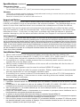
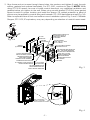
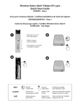
1. The power switch is in the “OFF” position (Fig. 5). Using frame or optional STI-1280 backplate
(recommended with all Weather Stopper® models) as a template, mark mounting holes on
wall taking into consideration placement of pull station or refer to Fig. 1 for dimensional
hole placement from center of clear opening. NOTE: Be sure cover will not interfere with
operation of the pull station when installed.
2. If using STI-1280 backplate, refer to Fig. 2 and 3 for install instructions depending on your
application. NOTE: When drilling hole in backplate NEMA 3R integrity is compromised.
Weather Stopper, STI-1250, is designed to meet the requirements of IP54.
FIND CENTER OF
PULL STATION
AND USE GIVEN
DIMENSIONS TO
CENTER PULL STATION
IN VISIBLE OPENING
OF COVER. DRILL
4 HOLES PER STEP 2.
LIFT HERE
I N CASE OF FI RE - LI FT COVER
PULL FI RE ALARM
4.9375 in.
(125mm)
2 in.
(51mm)
3.125 in.
(79mm)
6.25 in.
(159mm)
IF DRILLING INTO MASONRY
OR DRYWALL USE PROVIDED
ANCHORS. DRILL (4) 1/4”
(6.3mm) HOLES 1 1/4” DEEP. IF
DRILLING INTO WOOD, DRILL
(4) 5/32” (3.9mm) HOLES 1 1/4”
DEEP. DO NOT USE ANCHORS
IF DRILLING INTO WOOD.
EXISTING
PULL STATION
BACKPLATE
NOTE: WHEN DRILLING HOLE IN
BACKPLATE NEMA 3R INTEGRITY
IS COMPROMISED
ADHESIVE SIDE
WHEN GASKETS ARE USED, INSTALL
GASKET PROVIDED BY PEELING OFF
BACKING PAPER AND APPLY WITH
ADHESIVE FACING WALL. ALIGN HOLES
IN GASKET WITH HOLES DRILLED AND
STICK ON MOUNTING SURFACE.
OPTIONAL STI-1103
RELAY BOARD
RED +
BLACK –
GREEN NORMALLY OPEN
BLUE COMMON
WHITE NORMALLY CLOSED
3/32 in. ALLEN WRENCH
(NOT PROVIDED)
SWITCH LOCKING SCREW
5 INCHES OF CABLE IS
PROVIDED FOR SERVICE LOOP.
MAKE SURE THIS LOOP AND
ALL OTHER CABLES DO NOT
INTERFERE WITH STATION
OPERATION.
TO LOCK POWER SWITCH IN
THE "OFF" OR "ON" POSITION
TIGHTEN LOCKING SCREW FULLY
UNTIL SCREW MAKES CONTACT
WITH SWITCH PAD AS SHOWN.
OFF
OPTIONAL RELAY CONTACT SETTINGS
STI MODELS 1100RC, 1130RC, 1150RC AND 1155RC
USE ONLY
9 VOLT BATTERY
JUMPER USED ON STANDARD 9
VOLT INTERNALLY
POWERED MODELS
JUMPER INSTALLED ON "RC" MODELS
FOR EXTERNALLY SUPPLIED 12VDC OR
24VDC POWER
NOTE: SMALL CONNECTOR ON JUMPER
FITS INTO PLUG ON RELAY BOARD
THIS JUMPER IS INCLUDED WITH "RC"
MODELS FOR USE WHEN INTERNAL
9VDC BATTERY POWER IS REQUIRED.
(BATTERY NOT INCLUDED)
SMALL CONNECTOR ON JUMPER FITS
INTO PLUG ON RELAY BOARD
USING THIS JUMPER REQUIRES
VOLTAGE SELECTOR SET TO 9V
STI-1103 RELAY
BOARD IS USED ON
"RC" MODELS
VOLTAGE SELECTOR
9V 24V
FACTORY VOLTAGE SETTINGS:
BATTERY POWERED UNITS: 9 VOLT
REMOTE POWER "RC" UNITS: 24 VOLT
USE 24 VOLT SETTING FOR USE WITH
12 VOLT DC INPUT POWER
VOLUME
LOW HI
FACTORY VOLUME SETTING: HIGH
EXPLODED
ELECTRONIC VIEW
ADDED
SILICONE
{
12-24 VDC
STEP 1
STEP 1
FLUSH MOUNT
WITH OPTIONS

- 5 -
Fig. 4
PUSH IN
PULL DOWN
B
NOTE: HOLD FRAME TO
THE WALL (IF MOUNTED)
WHILE ATTACHING THE LANYARD
Fig. 3A
Fig. 3
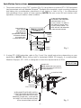
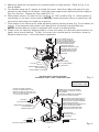
3. Align frame and put screws through frame holes, into anchors and tighten (if used, through
spacer, gaskets and optional backplate). For STI-1200, continue to Step 8. NOTE: When
using STI-3100 spacer, be sure to install conduit knockout, any additional ventilation and
gaskets before you tighten to the wall. When using conduit gasket STI-3004, place gasket
around conduit in proper location and install the spacer. For added protection a bead of
siliconemaybeappliedtoconduitttingandbetweenSTI-1280backplateandwall(Fig.3A).
RefertoexplodedviewofushandsurfacemountinstallationoptionsFig.2and3.Weather
Stopper, STI-3150, IP equivalency may vary depending on selection of conduit inserts used.
SURFACE MOUNT
WITH OPTIONS
FIND CENTER OF
PULL STATION
AND USE GIVEN
DIMENSIONS TO
CENTER PULL STATION
IN VISIBLE OPENING
OF COVER. DRILL
4 HOLES PER STEP 2.
LIFT HERE
I N CASE OF FIRE - L I FT COVER
PULL FI RE ALARM
4.9375 in.
(125mm)
2 in.
(51mm)
3.125 in.
(79mm)
6.25 in.
(159mm)
IF DRILLING INTO MASONRY
OR DRYWALL USE PROVIDED
ANCHORS. DRILL (4) 1/4”
(6.3mm) HOLES 1 1/4” DEEP. IF
DRILLING INTO WOOD, DRILL
(4) 5/32” (3.9mm) HOLES 1 1/4”
DEEP. DO NOT USE ANCHORS
IF DRILLING INTO WOOD.
EXISTING
PULL STATION
BACKPLATE
NOTE: WHEN DRILLING HOLE IN
BACKPLATE NEMA 3R INTEGRITY
IS COMPROMISED
ADHESIVE SIDE
WHEN GASKETS ARE USED, INSTALL
GASKET PROVIDED BY PEELING OFF
BACKING PAPER AND APPLY WITH
ADHESIVE FACING WALL. ALIGN HOLES
IN GASKET WITH HOLES DRILLED AND
STICK ON MOUNTING SURFACE.
OPTIONAL STI-1103
RELAY BOARD
RED +
BLACK –
GREEN NORMALLY OPEN
BLUE COMMON
WHITE NORMALLY CLOSED
3/32 in. ALLEN WRENCH
(NOT PROVIDED)
SWITCH LOCKING SCREW
5 INCHES OF CABLE IS
PROVIDED FOR SERVICE LOOP.
MAKE SURE THIS LOOP AND
ALL OTHER CABLES DO NOT
INTERFERE WITH STATION
OPERATION.
TO LOCK POWER SWITCH IN
THE "OFF" OR "ON" POSITION
TIGHTEN LOCKING SCREW FULLY
UNTIL SCREW MAKES CONTACT
WITH SWITCH PAD AS SHOWN.
OFF
OPTIONAL RELAY CONTACT SETTINGS
STI MODELS 1100RC, 1130RC, 1150RC AND 1155RC
USE ONLY
9 VOLT BATTERY
JUMPER USED ON STANDARD 9
VOLT INTERNALLY
POWERED MODELS
JUMPER INSTALLED ON "RC" MODELS
FOR EXTERNALLY SUPPLIED 12VDC OR
24VDC POWER
NOTE: SMALL CONNECTOR ON JUMPER
FITS INTO PLUG ON RELAY BOARD
THIS JUMPER IS INCLUDED WITH "RC"
MODELS FOR USE WHEN INTERNAL
9VDC BATTERY POWER IS REQUIRED.
(BATTERY NOT INCLUDED)
SMALL CONNECTOR ON JUMPER FITS
INTO PLUG ON RELAY BOARD
USING THIS JUMPER REQUIRES
VOLTAGE SELECTOR SET TO 9V
STI-1103 RELAY
BOARD IS USED ON
"RC" MODELS
VOLTAGE SELECTOR
9V 24V
FACTORY VOLTAGE SETTINGS:
BATTERY POWERED UNITS: 9 VOLT
REMOTE POWER "RC" UNITS: 24 VOLT
USE 24 VOLT SETTING FOR USE WITH
12 VOLT DC INPUT POWER
VOLUME
LOW HI
FACTORY VOLUME SETTING: HIGH
EXPLODED
ELECTRONIC VIEW
ADDED
SILICONE
{
12-24 VDC
STEP 1
STEP 1
#10-3 1/2” SCREW
(4) PROVIDED
KIT-316 VENT
(NOT INCLUDED)
NOT RECOMMENDED FOR
AREAS WHERE DUST MAY
AFFECT DEVICE OPERATION
ANCHOR
(4) PROVIDED
STI-1280
BACKPLATE
EXISTING
PULL STATION
STI-3002 WEATHER GASKET
INSTALL ADHESIVE TOWARD
MOUNTING SURFACE AND
THICK END OF GASKET
TOWARDS TOP OF ASSEMBLY
FOR RETROFIT APPLICATIONS,
CUT GASKET AT THE BOTTOM TO
INSTALL BEHIND CONDUIT
INSERT PLASTIC KNOCK-OUT,
INTO SPACER NOTCH IF
CONDUIT NOT NEEDED
(2) PROVIDED
STI-3004 GASKET
NOTE: USE 1/2 in. WITH
3/4 in. CONDUIT
STI-3104 CONDUIT SPACER
SHOWN WITH KIT-316
USE IN SPACER BOTTOM NOTCH
ONLY - FOR WATER DRAINAGE
AND REDUCED CONDENSATION
BREAK OUT ALL FOUR
CONDUIT INSERTS AND
TRIM SHARP EDGES
BEFORE INSTALLATION

- 6 -
Fig. 6
FIND CENTER OF
PULL STATION
AND USE GIVEN
DIMENSIONS TO
CENTER PULL STATION
IN VISIBLE OPENING
OF COVER. DRILL
4 HOLES PER STEP 2.
LIFT HERE
I N CASE OF FIRE - L I FT COVER
PULL FI RE ALARM
4.9375 in.
(125mm)
2 in.
(51mm)
3.125 in.
(79mm)
6.25 in.
(159mm)
IF DRILLING INTO MASONRY
OR DRYWALL USE PROVIDED
ANCHORS. DRILL (4) 1/4”
(6.3mm) HOLES 1 1/4” DEEP. IF
DRILLING INTO WOOD, DRILL
(4) 5/32” (3.9mm) HOLES 1 1/4”
DEEP. DO NOT USE ANCHORS
IF DRILLING INTO WOOD.
EXISTING
PULL STATION
BACKPLATE
NOTE: WHEN DRILLING HOLE IN
BACKPLATE NEMA 3R INTEGRITY
IS COMPROMISED
ADHESIVE SIDE
WHEN GASKETS ARE USED, INSTALL
GASKET PROVIDED BY PEELING OFF
BACKING PAPER AND APPLY WITH
ADHESIVE FACING WALL. ALIGN HOLES
IN GASKET WITH HOLES DRILLED AND
STICK ON MOUNTING SURFACE.
OPTIONAL STI-1103
RELAY BOARD
RED +
BLACK –
GREEN NORMALLY OPEN
BLUE COMMON
WHITE NORMALLY CLOSED
3/32 in. ALLEN WRENCH
(NOT PROVIDED)
SWITCH LOCKING SCREW
5 INCHES OF CABLE IS
PROVIDED FOR SERVICE LOOP.
MAKE SURE THIS LOOP AND
ALL OTHER CABLES DO NOT
INTERFERE WITH STATION
OPERATION.
TO LOCK POWER SWITCH IN
THE "OFF" OR "ON" POSITION
TIGHTEN LOCKING SCREW FULLY
UNTIL SCREW MAKES CONTACT
WITH SWITCH PAD AS SHOWN.
OFF
OPTIONAL RELAY CONTACT SETTINGS
STI MODELS 1100RC, 1130RC, 1150RC AND 1155RC
USE ONLY
9 VOLT BATTERY
JUMPER USED ON STANDARD 9
VOLT INTERNALLY
POWERED MODELS
JUMPER INSTALLED ON "RC" MODELS
FOR EXTERNALLY SUPPLIED 12VDC OR
24VDC POWER
NOTE: SMALL CONNECTOR ON JUMPER
FITS INTO PLUG ON RELAY BOARD
THIS JUMPER IS INCLUDED WITH "RC"
MODELS FOR USE WHEN INTERNAL
9VDC BATTERY POWER IS REQUIRED.
(BATTERY NOT INCLUDED)
SMALL CONNECTOR ON JUMPER FITS
INTO PLUG ON RELAY BOARD
USING THIS JUMPER REQUIRES
VOLTAGE SELECTOR SET TO 9V
STI-1103 RELAY
BOARD IS USED ON
"RC" MODELS
VOLTAGE SELECTOR
9V 24V
FACTORY VOLTAGE SETTINGS:
BATTERY POWERED UNITS: 9 VOLT
REMOTE POWER "RC" UNITS: 24 VOLT
USE 24 VOLT SETTING FOR USE WITH
12 VOLT DC INPUT POWER
VOLUME
LOW HI
FACTORY VOLUME SETTING: HIGH
EXPLODED
ELECTRONIC VIEW
ADDED
SILICONE
{
12-24 VDC
STEP 1
STEP 1
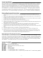
4. Make any external connections for remote power or relay options. Refer to Fig. 5 for
wiring details.
5. For models using the 2” spacer to install the cover, insert the cable end stop into the
pocket on the inside of the frame. Hold the frame against the wall and pull the cable to
lock into the slot. Repeat for 2nd cable (FIG. 4).
6. Slide power switch, on back of horn housing, to “ON” position (Fig. 5). When power is
connected to unit horn should sound. NOTE: If external power source is used horn will
not sound until power is turned on at source.
7. Push switch in to silence horn while tightening switch locking screw (Fig. 5 for location of
screw).Thispreventsslideswitchfrombeingshutoduringunauthorizeduse.
NOTE: Surface Mount version is shipped with screw in locked position.
8. Close cover on frame by aligning tabs on cover with slots on frame and push bottom on
tightly, horn should silence. To test: lift cover, horn should sound, and return cover to
frame to silence horn. Unit is armed for operation.
Fig. 5
FIND CENTER OF
PULL STATION
AND USE GIVEN
DIMENSIONS TO
CENTER PULL STATION
IN VISIBLE OPENING
OF COVER. DRILL
4 HOLES PER STEP 2.
LIFT HERE
I N CASE OF FIRE - L I FT COVER
PULL FI RE ALARM
4.9375 in.
(125mm)
2 in.
(51mm)
3.125 in.
(79mm)
6.25 in.
(159mm)
IF DRILLING INTO MASONRY
OR DRYWALL USE PROVIDED
ANCHORS. DRILL (4) 1/4”
(6.3mm) HOLES 1 1/4” DEEP. IF
DRILLING INTO WOOD, DRILL
(4) 5/32” (3.9mm) HOLES 1 1/4”
DEEP. DO NOT USE ANCHORS
IF DRILLING INTO WOOD.
EXISTING
PULL STATION
BACKPLATE
NOTE: WHEN DRILLING HOLE IN
BACKPLATE NEMA 3R INTEGRITY
IS COMPROMISED
ADHESIVE SIDE
WHEN GASKETS ARE USED, INSTALL
GASKET PROVIDED BY PEELING OFF
BACKING PAPER AND APPLY WITH
ADHESIVE FACING WALL. ALIGN HOLES
IN GASKET WITH HOLES DRILLED AND
STICK ON MOUNTING SURFACE.
OPTIONAL STI-1103
RELAY BOARD
RED +
BLACK –
GREEN NORMALLY OPEN
BLUE COMMON
WHITE NORMALLY CLOSED
3/32 in. ALLEN WRENCH
(NOT PROVIDED)
SWITCH LOCKING SCREW
5 INCHES OF CABLE IS
PROVIDED FOR SERVICE LOOP.
MAKE SURE THIS LOOP AND
ALL OTHER CABLES DO NOT
INTERFERE WITH STATION
OPERATION.
TO LOCK POWER SWITCH IN
THE "OFF" OR "ON" POSITION
TIGHTEN LOCKING SCREW FULLY
UNTIL SCREW MAKES CONTACT
WITH SWITCH PAD AS SHOWN.
OFF
OPTIONAL RELAY CONTACT SETTINGS
STI MODELS 1100RC, 1130RC, 1150RC AND 1155RC
USE ONLY
9 VOLT BATTERY
JUMPER USED ON STANDARD 9
VOLT INTERNALLY
POWERED MODELS
JUMPER INSTALLED ON "RC" MODELS
FOR EXTERNALLY SUPPLIED 12VDC OR
24VDC POWER
NOTE: SMALL CONNECTOR ON JUMPER
FITS INTO PLUG ON RELAY BOARD
THIS JUMPER IS INCLUDED WITH "RC"
MODELS FOR USE WHEN INTERNAL
9VDC BATTERY POWER IS REQUIRED.
(BATTERY NOT INCLUDED)
SMALL CONNECTOR ON JUMPER FITS
INTO PLUG ON RELAY BOARD
USING THIS JUMPER REQUIRES
VOLTAGE SELECTOR SET TO 9V
STI-1103 RELAY
BOARD IS USED ON
"RC" MODELS
VOLTAGE SELECTOR
9V 24V
FACTORY VOLTAGE SETTINGS:
BATTERY POWERED UNITS: 9 VOLT
REMOTE POWER "RC" UNITS: 24 VOLT
USE 24 VOLT SETTING FOR USE WITH
12 VOLT DC INPUT POWER
VOLUME
LOW HI
FACTORY VOLUME SETTING: HIGH
EXPLODED
ELECTRONIC VIEW
ADDED
SILICONE
{
12-24 VDC
STEP 1
STEP 1

- 7 -
Polycarbonate Cleaning Instructions
Rinse with water to remove abrasive dust and dirt. Wash with soap or mild detergent, using
a soft cloth. Rinse once more, then dry with a soft cloth or chamois. Exercise caution when
using water inside enclosure. Make sure unit is completely dry inside before reassembling. To
remove grease or wet paint from exterior of cover, rub gently with a cloth thoroughly wetted
withNaptha.Thenwashandrinse.(Donotuserazorblades.)
Options Available
KIT-316 Louvers for STI-3100
KIT-H19015 Two 3/32” Allen wrenches
STI-1102 Replacement horn for cover with alarm
STI-1280 Backplate
STI-3002 Weather gasket
STI-3003 Conduit gasket
STI-3100 2” conduit spacer with ½” conduit entry
STI-3104 2” conduit spacer with ¾” conduit entry (includes one ¾” conduit entry gasket)
Gasket Installation
Use of gaskets is necessary to ensure a proper seal in weatherproof applications. Weather
Stopper models ship complete with all necessary gaskets and should be used accordingly.
Forushmountweatherapplications,oneSTI-3002mustbeusedbetweentheframeor
spacer and wall or backplate (see Fig. 3). An STI-3004 gasket must be used around all
entering conduit. For surface mount applications, the conduit insert with holes is available
for installation in the bottom knockout of the conduit spacer. This helps prevent excessive
condensation buildup; but may allow for dust entry. STI recommends gasket replacement
everyveyears.(ULrequireslistingofpullstationtobeULListedforoutdoorinstallations.)
Battery Replacement Instructions
1. Remove the cover from the frame. It is not necessary to remove the cables from the
frame.
2. Use a 3/32” allen wrench to loosen the button head screw located next to the switch far
enoughtoslidetheswitchtothe“o”position.
3. Holding the horn housing and cover in one hand, remove the button head screw located
on the top of the cover with the same allen wrench.
4. Set the clear cover aside and remove the horn housing cover.
5. Replace the battery with a 9 Volt battery only. Be careful to keep the wires away from the
slide switch and the micro-switch.
6. Reassembletheunitmakingsurethatthehornhousingtsintothetabsonthehorn
housing cover; and that this assembly is mounted evenly into the clear cover.
7. Replace the button head screw through the top of the clear cover and into the top of the
horn.
8. Slide the switch to the “on” position. The horn should sound.
9. Push the switch in to silence horn while tightening the “on” position locking screw.
10. Replace the cover onto the frame and test by removing the cover from the frame. The
horn should sound when removed and silence when cover is replaced. If unit does not
operate correctly, contact Safety Technology International, Inc.

- 8 -
STOPPER II SERIES IS
FEB2017
Printed in USA
Subject to change without notice.
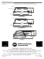
Product Dimensions
EXTERNAL DIMENSIONS: · Flush 7.1 x 10.0 x 3.3 in. (180 x 254 x 84 mm)
W x H x D · Surface 7.23 x 10.1 x 5.28 in. (184 x 256 x 134 mm)
SPACER
SPACER
COVER
COVER
HORN HOUSING
8.875 in.
(225mm)
6 in.
(152mm)
5.37 in.
(137mm)
8.875 in.
(225mm)
7.4 in.
(188mm)
5.34 in.
(136mm)
2 in.
(51mm)
.5 in.
(13mm)
3.175 in.
(81mm)
1 in.
(25mm)
3.175 in.
(81mm)
2 in.
(51mm)
.78 in.
(20mm) SPACER ADDS
2” DEPTH (50mm)
3 in.
(76mm)
4 in.
(102mm) 5 in.
(127mm)
5.5 in.
(140mm)
6.81 in.
(173mm)
1.61 in.
(41mm)
2.32 in.
(59mm)
2.73 in.
(70mm)
3.18 in.
(81mm)
3.30 in.
(84mm)
5.28 in.
(134mm)
7.23 in.
(184mm)
10.07 in.
(256mm)
SIDE VIEW
Models with Horn
SIDE VIEW
Models without Horn
END VIEW
All Models
2306 Airport Rd • Waterford, MI 48327, USA
Phone: 248-673-9898 • [email protected] • www.sti-usa.com
Taylor House • 34 Sherwood Road • Bromsgrove, Worcestershire • B60 3DR • England
Tel: +44 (0)1527 520 999 • [email protected] • www.sti-emea.com
Unit 7A • Lockhead Avenue • Airport Business Park • Waterford • X91 HWF2 • Ireland
[email protected] • www.sti-emea.com
USA EMEA
-
 1
1
-
 2
2
-
 3
3
-
 4
4
-
 5
5
-
 6
6
-
 7
7
-
 8
8


STI 1100 Stopper II Series Pull Station Cover Manuel utilisateur
- Taper
- Manuel utilisateur
dans d''autres langues
Documents connexes
Autres documents
-
 Safety Technology International STI-3350 Guide d'installation
-
Miller KH360783 Le manuel du propriétaire
-
-
-
-
 Safety Technology International STI-3360 Guide d'installation
-

