eufy Security T8210C Mode d'emploi
- Catégorie
- Mur
- Taper
- Mode d'emploi

Anker Innovations Limited. All rights reserved. eufy Security and eufy Security Logo
are trademarks of Anker Innovations Limited, registered in the United States and
other countries. All other trademarks are the property of their respective owners.
51005001867 V04
QUICK
START GUIDE
Video Doorbell 2K (Battery-Powered)

English 01
TABLE OF
CONTENTS
What’s Included 02
Product Overview 04
How The System Works 06
Connecting The Homebase 07
Setting Up The System
08
Determining The Power Option 09
Finding A Mounting Spot 11
13 Mounting The Bracket
16 Mounting The Doorbell
17 Detaching The Doorbell
18 Recharging The Doorbell
19
Powering The Doorbell With Existing
Doorbell Wires
27 Notice
30 Customer Service

2 English English 3
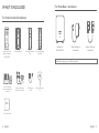
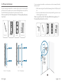
WHAT’S INCLUDED
For Video Doorbell Installation
QSG
Video Doorbell 2K
(Battery-Powered)
Model: T8210C
Screw Packs (Spare
screws and anchors are
included)
Quick Start Guide
Screw Hole Positioning
Card
Doorbell Detaching
Pin
15° Mounting Wedge
(Optional)
Mounting Bracket
Extension Wires and
Wire Nuts (Optional)
USB Charging
Cable
For HomeBase 2 Installation
HomeBase 2
Model:T8010X
Power Adapter for
HomeBase 2
Ethernet Cable for
HomeBase 2
Note: Power plug may vary in different regions.

4 English English 5
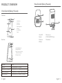
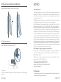
PRODUCT OVERVIEW
Video Doorbell (Battery Powered)
Front view:
1
3
5
7
2
4
6
1. Motion Sensor
2. Microphone
3. Camera Lens
4. Ambient Light Sensor
5. LED Ring
6. Doorbell Button
7. Speaker
Rear View:
1
2
3
4
1. Micro USB Charging Port
2. SYNC/RESET Button
3. Power Terminals for Existing
Doorbell Wire (Optional)
4. Detaching Mechanism
Operation How-to
Power on Press and release the SYNC button
Add doorbell to HomeBase Press and hold the SYNC button until you hear a beep
Power off the doorbell Quick-press the SYNC button 5 times in 3 seconds.
Reset the doorbell Press and hold the SYNC button for 10 seconds.
Video Doorbell (Battery Powered)
2
3
4 5 6
7
1
1. Status LED
2. Speaker
3. Power port
4. USB port
5. Ethernet port
6. SYNC/ALARM OFF button
7. Reset button

6 English English 7
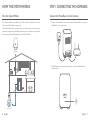
HOW THE SYSTEM WORKS
How the System Works
The video doorbell system includes 2 parts. One is the video doorbell at your door.
The other is the HomeBase in your house.
The video doorbell detects motion at your porch and allows you to answer the door
anytime and anywhere.The HomeBase stores video clips on its built-in storage. When
someone rings the doorbell, people in the house will be notied.
Doorbell Chime
Video Doorbell
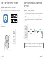
STEP 1 CONNECTING THE HOMEBASE
Connect the HomeBase 2 to the Internet
1. Power on the HomeBase 2, then use the ethernet cable provided to connect the
HomeBase 2 to your home router.
2. The LED indicator turns blue (this may take up to 1min) when HomeBase 2 is
ready for setup.

8 English English 9
STEP 2 SETTING UP THE SYSTEM
Download the App and Set up the System
Download the eufy Security app from the App Store (iOS devices) or Google Play
(Android devices).
Sign up for a eufy Security account, then follow the onscreen instructions to
complete the setup.
STEP 3 DETERMINING THE POWER
OPTION
Option 1 - Battery Powered
1. If you don’t have existing doorbell wiring at the front door, use the built-in battery.
You are free to determine the doorbell position and the mounting is easy and
quick.
2. When the doorbell battery level is low, you need to detach and charge it.
3. If you choose this option, please jump to STEP 4 FINDING A MOUNTING
SPOT.
6 months
Note: The battery life varies depending on usage. In most common cases, a
doorbell may have up to 10 events per day and each recording lasts 20 seconds on
average. Under this scenario, the doorbell battery life can last up to 6 months.

10 English English 11
Option 2 - Doorbell Wire Powered
1. If you have existing and working doorbell wiring at the front door, the doorbell
will be powered by the wires constantly. So you don’t need to detach and charge
it after installation.
2. Since the doorbell is connected to the wires, the mounting position is limited.
3. If you choose this option, please jump to Appendix 3 Powering the Doorbell
with Doorbell Wires.
8 - 24V AC Doorbell Wiring
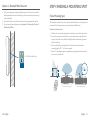
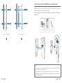
STEP 4 FINDING A MOUNTING SPOT
Find a Mounting Spot
Take the video doorbell to your front door and check the live view on the App at the
same time. Find a location where you can get the desired eld of view.
Consider the below factors:
1. Check if you can reuse the existing holes and anchors on the wall or door frame.
2. If you want to place the doorbell close to a side wall, make sure the wall doesn’t
show up in the eld of view. Otherwise IR light will be reected and night vision
will become blurry.
3. If you are drilling the mounting holes for the rst time, the recommended
mounting height is 48" / 1.2 m from the ground.
4. Use the 15° mounting wedge as a supplementary mounting bracket if you wish to
see more on a specic side.
1.76m(5’9”)
1.2m (48")
0.3m
(12")
1m
(40")
15°
Without 15° Mounting wedge With 15° Mounting wedge
Door Door
Video Doorbell Video Doorbell

12 English English 13
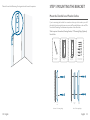
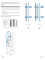
Place the Screw Hole Positioning Card against the wall to mark the position. STEP 5 MOUNTING THE BRACKET
Mount the Doorbell on a Wooden Surface
If you’re mounting the doorbell on a wooden surface, you don’t need to pre-drill
pilot holes. Use the provided screws to secure the Mounting Bracket on the wall, The
Screw Hole Positioning Card indicates the position of the screw holes.
What is required: Screwdriver, Mounting Bracket, 15° Mounting Wedge (Optional),
Screw Packs
Phillips-Head Screwdriver
(not provided)
Wall Wall
Mounting
Bracket
Mounting
Wedge
Mounting
Bracket
Mounting Bracket
(Attached to 15° Mounting
Wedge)
15° Mounting
Wedge (Optional)
Screw Packs (Spare screws
and anchors are included.)
Without 15° Mounting Wedge With 15° Mounting Wedge

14 English English 15
Mount the Doorbell on Surfaces Made Out of Hard
Materials
1. If you’re mounting the doorbell on a surface made out of hard materials, like brick,
concrete, stucco, drill 2 holes through the Screw Hole Positioning Card with a
15/64”(6mm) drill bit.
2. Insert the provided anchors, and then use the provided long screws to secure the
Mounting Bracket on the wall.
What is required: Power Drill, 15/64”(6 mm) Drill Bit, Mounting Bracket, 15°
Mounting Wedge (Optional), Screw Packs
Power Drill
(not provided) 15/64”(6 mm) Drill Bit
Mounting Bracket
(Attached to 15° Mounting
Wedge)
15° Mounting
Wedge (Optional)
Screw Packs (Spare screws
and anchors are included.)
1
2 2
Wall Wall
Mounting
Bracket
Mounting
Wedge
Mounting
Bracket
Without 15° Mounting Wedge With 15° Mounting Wedge

16 English English 17
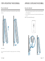
STEP 6 MOUNTING THE DOORBELL
Mount the Doorbell
Align the doorbell on top and then snap it on the bottom. Press it down until it clicks
into place.
You’re all set!
If you want to detach the doorbell or recharge it, please refer to the following
sections.
APPENDIX 1 DETACHING THE DOORBELL
Detach the Doorbell
1. Use the doorbell detaching pin provided if you wish to detach the doorbell from
the Mounting Bracket.
2. Press and hold the hole on the bottom of the doorbell and then lift its bottom to
take it off.
What is required: Doorbell Detaching Pin
Doorbell
Detaching Pin

18 English English 19
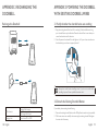
APPENDIX 2 RECHARGING THE
DOORBELL
Recharge the Doorbell
LED indication Charging: Solid orange
Fully charged: Solid cyan
Charging time 6 hours from 0% to 100%
APPENDIX 3 POWERING THE DOORBELL
WITH EXISTING DOORBELL WIRES
3.1 Verify whether the doorbell wires are working
1. Ring the existing doorbell to check if it is working. If the doorbell doesn’t ring,
your doorbell wires may be defective. Power the doorbell on its own battery or
consult an electrician to x the wires.
2. Shut off power at the breaker. Turn the lights on / off in your home to make sure
the electricity in your house is properly shut off.
OFF
OFF
Always be careful when handling wires. If you’re not comfortable
installing it yourself, have a qualied electrician do it.
3.2 Detach the Existing Doorbell Button
If you already have existing doorbell wiring:
1. Remove the existing doorbell button with a Phillips-Head screwdriver (not provided).
2. Pull the two wires out carefully when removing the existing doorbell. Straighten
the wire ends if necessary.

20 English English 21
What is required: Philips-Head Screwdriver
Phillips-Head Screwdriver
(User provides it.)
3.3 Find a Mounting Spot
1. Determine the mounting position of the doorbell. Consider the below factors:
① Check if you can reuse the existing holes and anchors on the wall or door
frame.
② If you are drilling the mounting holes for the first time, the recommended
mounting height is 48" / 1.2 m from the ground.
③ Use the 15° mounting wedge as a supplementary mounting bracket if you wish
to see more on a specic side.
1.76m(5’9”)
1.2m (48")
0.3m
(12")
1m
(40")
15°
Without 15° Mounting wedge With 15° Mounting wedge
Door Door
Video Doorbell Video Doorbell
2. Place the Screw Hole Positioning Card against the wall to mark the position.

22 English English 23
3.4 Mount the Bracket
If you’re mounting the doorbell on a wooden surface, you don’t need to pre-drill
pilot holes. Use the provided screws to secure the Mounting Bracket on the wall. The
Screw Hole Positioning Card indicates the position of the screw holes.
What is required: Power Drill, Mounting Bracket, 15° Mounting Wedge (Optional),
Screw Packs
Phillips-Head Screwdriver
(User provides it.)
Wall Wall
Mounting
Bracket
Mounting
Wedge
Mounting
Bracket
Mounting Bracket
(Attached to 15° Mounting
Wedge)
15° Mounting
Wedge (Optional)
Screw Packs (Spare screws
and anchors are included.)
Without 15° Mounting Wedge With 15° Mounting Wedge
If you’re mounting the doorbell on a surface made out of hard materials, like brick,
concrete, stucco:
① Drill 2 holes through the Screw Hole Positioning Card with 15/64”(6mm) drill
bit.
② Insert the provided anchors, and then use the provided long screws to secure
the Mounting Bracket on the wall.
What is required: Power Drill, 15/64”(6mm) Drill Bit, Mounting Bracket, 15°
Mounting Wedge (Optional), Screw Packs
Power Drill
(not provided) 15/64”(6 mm) Drill Bit
Mounting Bracket
(Attached to 15° Mounting
Wedge)
15° Mounting
Wedge (Optional)
Screw Packs (Spare screws
and anchors are included.)
1

24 English English 25
2 2
Wall Wall
Mounting
Bracket
Mounting
Wedge
Mounting
Bracket
Without 15° Mounting Wedge With 15° Mounting Wedge
3.5 Connect the Doorbell Wires to the Doorbell
Connect the wires to the terminals at the back of the doorbell, then tighten the
terminal screws. Wire can connect to any terminal.
What is required: Wires and Wire Nuts (Optional), Video Doorbell, Philips-head
Screwdriver
Extension Wires and
Wire Nuts (Optional)
Video Doorbell 2K (Wired)
Model: T8210C
Phillips-Head Screwdriver
(User provides it.)
Note:
• To prevent short-circuit, make sure the wires are not touching each other after
connecting them to the terminals.
• If the wires are too short, use the extension wires and wire nuts provided to
make them longer. Use electrical wiring tape instead if there is no more space on
the wall for wire nuts.

26 English English 27
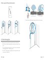
3.6 Mount the Doorbell on the Bracket
Align the doorbell on top and then snap it on the bottom.
3.7 Restore Power
Switch the master circuit breaker back to ON.
ON
ON
You’re all set!
If you want to detach the doorbell or recharge it, please refer to the corresponding
sections.
NOTICE
FCC Statement
This device complies with Part 15 of the FCC Rules. Operation is subject to the
following two conditions: (1) this device may not cause harmful interference, and (2)
this device must accept any interference received, including interference that may
cause undesired operation.
Warning: Changes or modications not expressly approved by the party responsible
or compliance could void the user's authority to operate the equipment.
Note: This equipment has been tested and found to comply with the limits for a Class
B digital device, pursuant to Part 15 of the FCC Rules. These limits are designed to
provide reasonable protection against harmful interference in a residential installation.
This equipment generates uses and can radiate radio frequency energy and, if not
installed and used in accordance with the instructions, may cause harmful interference
to radio communications. However, there is no guarantee that interference will not
occur in a particular installation. If this equipment does cause harmful interference to
radio or television reception, which can be determined by turning the equipment off
and on, the user is encouraged to try to correct the interference by one or more of
the following measures: (1) Reorient or relocate the receiving antenna. (2) Increase the
separation between the equipment and receiver. (3) Connect the equipment into an
outlet on a circuit different from that to which the receiver is connected. (4) Consult
the dealer or an experienced radio/TV technician for help.
FCC Radio Frequency Exposure Statement
The device has been evaluated to meet general RF exposure requirements. The device
can be used in xed/mobile exposure condition. The min separation distance is 20cm.
Notice: Shielded cables
All connections to other computing devices must be made using shielded cables to
maintain compliance with FCC regulations.
The following importer is the responsible party:
Company Name: POWER MOBILE LIFE, LLC
Address: 10900 NE 8th St, Ste 501, Bellevue WA 98004
Telephone:1-800-988-7973
IC Statement
This device complies with Industry Canada licence-exempt RSS standard(s). Operation
is subject to the following two conditions:

28 English English 29
(1) this device may not cause interference, and
(2) this device must accept any interference, including interference that may cause
undesired operation of the device."
Le présent appareil est conforme aux CNR d'Industrie Canada applicables aux
appareils radio exempts de licence. L'exploitation est autorisée aux deux conditions
suivantes:
(1) l'appareil nedoit pas produire de brouillage, et
(2) l'utilisateur de l'appareil doit accepter tout brouillage radioélectrique subi, même
si le brouillage est susceptible d'en compromettre le fonctionnement."
This Class B digital apparatus complies with Canadian ICES-003.
Cet appareil numérique de la classe B est conforme à la norme NMB-003 du Canada.
IC RF Statement
When using the product, maintain a distance of 20cm from the body to ensure
compliance with RF exposure requirements.
Lors de l'utilisation du produit, maintenez une distance de 20 cm du corps an de
vous conformer aux exigences en matière d'exposition RF.
This product complies with the radio interference requirements of the
European Community
Declaration of Conformity
Hereby, Anker Innovations Limited declares that this device is in compliance with the
essential requirements and other relevant provisions of Directive 2014/53/EU. For the
declaration of conformity, visit the website: https://uk.eufylife.com.
This product complies with the radio interference requirements of the
United Kingdom
Declaration of Conformity
Hereby, Anker Innovations Limited declares that this device is in compliance with
Radio Equipment Regulations 2017(SI 2017/1206). The full text of the UK declaration
of conformity is available at the following internet address: https://uk.eufylife.com.
Do not use the Device in the environment at too high or too low temperature, never
expose the Device under strong sunshine or too wet environment.
T8210C: The suitable temperature for the device and accessories is -20°C to 50°C
(charging temperature 0℃ to 45℃)
T8010X: The suitable temperature for the device and accessories is -10°C to 45°C.
It is recommended to supply the device in an environment with a temperature that
ranges from 5°C~25°C.
When supplying, please place the device in an environment that has a normal room
temperature and good ventilation.
The adapter shall be installed near the equipment and shall be easily accessible.
Please ensure you use only the adapter offered by the manufacturer. Using an
unauthorized adapter may be dangerous and violate the Terms of Use and product
warranty.
This adapter is for indoor use only. The adapter type is KA2401A-1202000DE, rated
output voltage/current is 12Vdc/2A. The plug considered as disconnect device of
adapter.
RF exposure information
The Maximum Permissible Exposure (MPE) level has been calculated based on a distance
of d=20 cm between the device and the human body. To maintain compliance with RF
exposure requirement, use product that maintain a 20cm distance between the device
and human body.
Frequency bands and power as below:
Function Bands Operation Frequency Max. Power
SUB-1G (T8010X) SUB-1G 866-866.8MHz EIRP 5.24 dBm
Wi-Fi (T8010X) 2.4GHz 2412-2472MHz EIRP 18.40 dBm
Wi-Fi (T8210C) 2.4GHz 2412-2472MHz EIRP 19.98 dBm
The following importer is the responsible party (contract for EU matters):
Anker Innovations Deutschland GmbH I Georg-Muche-Strasse 3, 80807 Munich,
Germany
The following importer is the responsible party (contract for UK matters):
Anker Technology (UK) Limited I GNR8, 49 Clarendon Road, Watford, Hertfordshire,
WD17 1HP, United Kingdom
Warning
– replacement of a battery with an incorrect type that can defeat a safeguard;
– disposal of a battery into re or a hot oven, or mechanically crushing or cutting of a
battery, that can result in an explosion;
– leaving a battery in an extremely high temperature surrounding environment that can
result in an explosion or the leakage of ammable liquid or gas; and
– a battery subjected to extremely low air pressure that may result in an explosion or the
leakage of ammable liquid or gas.
Attention:
– remplacement d’une batterie par un type incorrect pouvant supprimer une protection
– mise au rebut d’une batterie dans un feu ou dans un four chaud, ou écrasement
mécanique ou coupure d’une batterie, susceptible de provoquer une explosion;
– maintien d’une batterie dans un environnement à très haute température pouvant

30 English English 31
provoquer une explosion ou la fuite de liquide ou de gaz inammables; et
– batterie soumise à une pression de l’air extrêmement faible pouvant provoquer une
explosion ou la fuite de liquide ou de gaz inammables.
This product is designed and manufactured with high quality materials and
components, which can be recycled and reused.
This symbol means the product must not be discarded as household waste,
and should be delivered to an appropriate collection facility for recycling.
Proper disposal and recycling helps protect natural resources, human health
and the environment. For more information on disposal and recycling of this
product, contact your local municipality, disposal service, or the shop where
you bought this product.
-
 1
1
-
 2
2
-
 3
3
-
 4
4
-
 5
5
-
 6
6
-
 7
7
-
 8
8
-
 9
9
-
 10
10
-
 11
11
-
 12
12
-
 13
13
-
 14
14
-
 15
15
-
 16
16
-
 17
17


eufy Security T8210C Mode d'emploi
- Catégorie
- Mur
- Taper
- Mode d'emploi
dans d''autres langues
- English: eufy Security T8210C User guide
Documents connexes
Autres documents
-
Eufy T8920 Mode d'emploi
-
TP-LINK tp-link Tapo D130 Wired Video Doorbell Mode d'emploi
-
Eufy PAP 22 Raccolta Carta Smoke Listener Mode d'emploi
-
TP-LINK tp-link Tapo D100C Tapo Smart Video Doorbell Wired Mode d'emploi
-
Ring Video Doorbell (2nd Generation) Manuel utilisateur
-
Maximus VD01-05A1W-BK Manuel utilisateur
-
Eufy C210 Mode d'emploi
-
REOLINK Video Doorbell PoE Video Doorbell WiFi Manuel utilisateur
-
Lorex LNWDB1-WK Guide de démarrage rapide
-
TOUCAN TVDP05GR Manuel utilisateur