KTM 69012034044 Le manuel du propriétaire
- Taper
- Le manuel du propriétaire

Information
Power Parts
www.ktm.com
69012034044
02. 2008 3.211.393
*3211393*

Danke, dass Sie sich für KTM Power Parts entschlossen haben.
Alle unsere Produkte wurden nach den höchsten Standards entwickelt und gefertigt, unter Verwendung der besten verfügbaren
Materialien.
KTM Power Parts sind rennerprobt und gewährleisten ultimative Performance.
KTM KANN NICHT VERANTWORTLICH GEMACHT WERDEN FÜR FALSCHE MONTAGE ODER VERWENDUNG DIESES PRODUKTS. Bitte
befolgen Sie die Montageanleitung. Wenn bei der Montage Unklarheiten auftreten, wenden Sie sich bitte an eine KTM Fachwerkstätte.
Danke.
Thank you for choosing KTM Power Parts!
All of our products are designed and built to the highest standards using the finest materials available.
KTM Power Parts are race proven to offer the ultimate in performance.
KTM WILL NOT BE HELD LIABLE FOR IMPROPER INSTALLATION OR USE OF THIS PRODUCT. Please follow all instructions provided. If you
are unsure of any installation procedure, please contact a certified KTM dealer.
Thank you.
Grazie per aver deciso di acquistare un prodotto KTM Power Parts.
Tutti i nostri prodotti sono stati sviluppati e realizzati secondo i massimi standard e con l'impiego dei migliori materiali disponibili.
Le KTM Power Parts sono collaudate nelle competizioni ed assicurano altissime prestazioni.
KTM NON PUÒ ESSERE RESA RESPONSABILE PER UN MONTAGGIO O USO IMPROPRIO DI QUESTO PRODOTTO. Per favore osservate le
istruzioni nel manuale d'uso.Se dovessero sorgere dei dubbi al montaggio, rivolgetevi ad un'officina specializzata KTM.
Grazie.
Nous vous remercions d'avoir choisi KTM Power Parts.
Tous nos produits ont été développés et réalisés selon les plus hauts standards et en utilisant les meilleurs matériaux disponibles.
Les Power Parts de KTM ont fait leurs preuves en compétition et garantissent les meilleures performances.
LA RESPONSABILITÉ DE KTM NE SAURAIT ÊTRE ENGAGÉE EN CAS D'ERREUR DANS LE MONTAGE OU L'UTILISATION DE CE PRODUIT.
Il convient de respecter les instructions de montage.
Si quelque chose n'est pas clair lors du montage, il faut s'adresser à un agent KTM.
Merci.
Gracias por haberse decidido por el Power Parts KTM.
Todos nuestros productos han sido desarrollados y producidos según los estándares más altos utilizando los mejores materiales
disponibles.
Las KTM Power Parts están probadas en competencia y garantizan un óptimo rendimiento.
NO SE PUEDE HACER RESPONSABLE A LA KTM POR UN MONTAJE O UN USO INCORRECTO DE ESTE PRODUCTO.
Le rogamos seguir las instrucciones para el montaje.
Si durante el montaje resultan confusiones le rogamos contactar a un taller especializado KTM.
Gracias.
DEUTSCH
2
ENGLISH
2
ESPANOL
2
ITALIANO
2
FRANCAIS
2

DEUTSCH
3
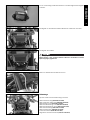
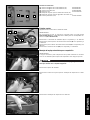
Montage Racingelektronik
HINWEIS:
Die Racingelektronik kann nur in Verbindung mit der optional erhältlichen
Racingverkleidung verwendet werden!
Der Motor muss kalt sein! Ansonsten besteht akute Verbrennungsgefahr
durch die Kühlflüssigkeit!
Kühlerverschluss demontieren.
Vorarbeiten
Stellen Sie das Motorrad auf den Seitenständer.
HINWEIS:
Es wird eine bei KTM erhältliche Hinterradhebevorrichtung (610.29.055.400)
mit dem Universal V-Adapter (610.29.055.120) empfohlen.
Kühlerverkleidung (7) links und rechts demontieren.
Frontverkleidung Oberteil (8) links und rechts demontieren.
Frontverkleidung Unterteil (9) links und rechts demontieren.
Abluftschacht (10) links und rechts demontieren.
Befestigungsschraube für Ansaugschnorchel rechts demontieren.
Ansaugschnorchel rechts entfernen.
Lieferumfang:
(1) Sechskant Bundschraube M6x25 (2x) 0024060206
(2) Sechskant Bundschraube M6x20 (2x) 0024060256
(3) Einpressmutter (8x) 54603055051
(4) Büchse (2x) 54613038150
(5) Halteblech-Steuergerät (1x)
(6) Halteblech-Spannungsregler (1x)
(7) Kabelbinder (5x) 44011076305
7
89
5416 2
10

DEUTSCH
4
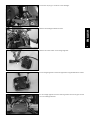
Befestigungsschraube für Ansaugschnorchel links demontieren.
Steuergerät von Zuluftschacht rechts demontieren.
Starter Interlock inkl. Gummischuh demontieren.
Rechte Befestigungsschraube Verkleidungskiel demontieren.
Ansaugschnorchel links entfernen.
Linke Befestigungsschraube Verkleidungskiel demontieren.

DEUTSCH
5
Scheinwerfer demontieren.
2x links.
Massekabel Spannungsregler trennen.
Steckverbindung Spannungsregler trennen.
Spannungsregler von Zuluftschacht links demontieren.
2x rechts.
HINWEIS:
Schrauben (1) können für die spätere Montage des Halteblechs-Steuergerät
wiederverwendet werden.
Schrauben (2) können für die spätere Montage des Halteblechs-Spannungsregler
wiederverwendet werden.
1
1
2
2

DEUTSCH
6
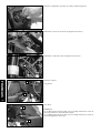
Spannungsregler mit Sechskantschrauben M6x25 auf Halteblech montieren.
Kabelbinder des Spannungsreglers entfernen.
Scheinwerfer nach vorne entfernen.
Spannungsregler mit dem Halteblech und den Originalschrauben auf
Scheinwerferträger montieren.
Steckverbindung Scheinwerfer trennen.

DEUTSCH
7
Kabel hinter dem linken Gabelholm neu verlegen.
Stecker und Kabel am Rahmen mit Kabelbinder fixieren.
Massekabel Spannungsregler wieder anschließen.
Steckverbindungen anschließen.
Halteblech-Steuergerät an Verkleidungsscheibe mit den Originalschrauben
montieren.

DEUTSCH
8
Starter Interlock hinter der Konsole fixieren.
Kabel hinter dem rechten Gabelholm neu verlegen.
Kabelbinder vom Kabelbaum rechts entfernen.
Stecker (1) für optional erhätliche Reifendruckanzeige (69012031000).
Steckverbindung Steuergerät trennen.
1

DEUTSCH
9
Die im Lieferumfang enthaltenen Büchsen in die Bohrungen des Steuergeräts
einsetzen.
Kabel mit Kabelbinder am Rahmen fixieren.
Steuergerät anschließen.
Spannungsregler wird heiß!
Darauf achten, dass genügen Abstand zwischen den Kabeln und dem
Spannungsregler gegeben ist.
Steuergerät mit Sechskantschrauben M6x20 auf Halteblech montieren.
Endmontage
Optional erhältliche Rennverkleidung montieren.
GFK-Frontverkleidung (690.08.101.000)
GFK-Untermotor-Verkleidung (690.08.160.000)
GFK-Kotflügel vorne (690.08.110.000)
GFK-Seitenverkleidung links (690.08.102.000)
GFK-Seitenverkleidung rechts (690.08.103.000)
GFK-Heckverkleidung (690.08.114.000)
GFK-Sitzverkleidung (690.08.147.000)
Schnellverschlüsse (690.08.901.050)
Gegenstück Schnellverschlüsse (450.07.040.050)

ENGLISH
10
Mounting the racing electronics
NOTE:
The racing electronics can be used only in combination with the optionally
available racing covers!
The engine must be cold! Otherwise, there is acute risk of scalding by the
coolant!
Remove the radiator cap.
Preparations
Lean the motorcycle on the side stand.
NOTE:
We recommend that you use a rear wheel lifting device as supplied by KTM
(610.29.055.400) with the Universal V-Adapter (610.29.055.120).
Remove the radiator covers (7) on the left and right.
Remove the upper front covers (8) on the left and right.
Remove the lower front covers (9) on the left and right.
Remove the exhaust air duct (10) on the left and right.
Remove the fixing screw for the intake snorkel on the right.
Remove the intake snorkel on the right.
Scope of delivery:
(1) Hexagonal collar screw, M6x25 (2x) 0024060206
(2) Hexagonal collar screw, M6x20 (2x) 0024060256
(3) Insert nuts (8x) 54603055051
(4) Bush (2x) 54613038150
(5) Retaining bracket control unit (1x)
(6) Retaining bracket voltage regulator (1x)
(7) Cable binder (5x) 44011076305
7
89
5416 2
10

ENGLISH
11
Remove the fixing screw for the intake snorkel on the left.
Remove the control unit from the air intake duct on the right.
Dismantle the starter interlock incl. rubber boot.
Remove the right fixing screw of the fairing keel.
Remove the intake snorkel on the left.
Left fixing screw
Remove the fairing keel.

ENGLISH
12
Remove the headlight.
2x left.
Disconnect the graound wire of the voltage regulator.
Disconnect the plug-in connector of the voltage regulator.
Remove the voltage regulator from the air intake duct on the left.
2x right.
NOTE:
The screws (1) can be used again for mounting the control unit retaining bra-
cket later.
The screws (2) can be used again for mounting the voltage regulator retai-
ning bracket later.
1
1
2
2

ENGLISH
13
Fit the voltage regulator on the retaining bracket using the M6x25 hex screws.
Remove the cable binder of the voltage regulator.
Remove the headlight towards the front.
Fit the voltage regulator with the retaining bracket and the original screws
on to the headlight bracket.
Disconnect the plug-in connector of the headlight.

ENGLISH
14
Reroute the cable behind the left front fork leg.
Fix the plugs and cable to the frame using cable binders. Reconnect the gra-
ound wire of the voltage regulator.
Reconnect the plug-in connectors.
Fit the control unit retaining bracket to the cover disc using the original screws.

ENGLISH
15
Fix the starter interlock behind the console.
Reroute the cable behind the right front fork leg.
Remove the cable binders from the cable harness on the right.
Connector (1) for optionally available tire pressure display (69012031000).
Disconnect the control unit plug-in connector.
1

ENGLISH
16
Insert the bushes supplied into the drill holes of the control unit.
Fox the cable to the frame using the cable binder.
Connect the control unit.
The voltage regulator gets hot!
Make sure there is enough space between the cables and the voltage regu-
lator.
Fit the control unit on the retaining bracket using the M6x20 hex screws.
Final steps
Fit the optionally available racing fairing.
GFK front cover (690.08.101.000)
GFK engine bottom cover (690.08.160.000)
GFK front fender (690.08.110.000)
GFK left side fairing (690.08.102.000)
GFK right side fairing (690.08.103.000)
GFK rear cover (690.08.114.000)
GFK seat cover (690.08.147.000)
Quick releases (690.08.901.050)
Counterpart of quick releases (450.07.040.050)

ITALIANO
17
Montaggio elettronica da competizione
NOTA BENE:
l'elettronica da competizione può essere utilizzata esclusivamente con il
rivestimento corrispondente disponibile a richiesta!
Il motore deve essere freddo! Sussiste altrimenti un grave pericolo di ustione
a causa del liquido di raffreddamento!
Smontare il tappo del radiatore.
Operazioni preliminari
Posizionare la motocicletta sul cavalletto laterale.
NOTA BENE:
Si consiglia un dispositivo di sollevamento della ruota posteriore
(610.29.055.400) disponibile presso KTM con adattatore universale a V
(610.29.055.120).
Smontare il rivestimento sinistro e destro del radiatore (7).
Smontare il rivestimento superiore frontale (8) sinistro e destro.
Smontare il rivestimento inferiore frontale (9) sinistro e destro.
Smontare la camera d'aria (10) di sinistra e destra.
Smontare la vite di fissaggio del tubo di aspirazione destro.
Rimuovere il tubo di aspirazione destro.
Ambito della fornitura:
(1) Vite flangiata a testa esagonale M6x25 (N. 2) 0024060206
(2) Vite flangiata a testa esagonale M6x20 (N. 2) 0024060256
(3) Dado ad innesto (N. 8) 54603055051
(4) Bussola (N. 2) 54613038150
(5) Centralina elettronica piastra (N. 1)
(6) Regolatore di tensione piastra (N. 1)
(7) Fascetta serracavi (N. 5) 44011076305
7
89
5416 2
10

ITALIANO
Smontare la vite di fissaggio del tubo di aspirazione sinistro.
Rimuovere la centralina elettrica destra dalla camera di aspirazione.
Smontare lo starter interlock, scarpetta in gomma compresa.
Smontare la vite di fissaggio destra dal rivestimento inferiore.
Rimuovere il tubo di aspirazione sinistro.
Vite di fissaggio sinistra.

ITALIANO
19
Smontare i fari.
N. 2 sinistra.
Staccare il cavo di massa dal regolatore di tensione.
Staccare il connettore dal regolatore di tensione.
Smontare il regolatore di tensione dalla camera di aspirazione sinistra.
N. 2 destra.
NOTA BENE:
le viti (1) possono essere utilizzate successivamente per montare la centra-
lina sulla piastra.
le viti (2) possono essere utilizzate successivamente per montare il regola-
tore di tensione sulla piastra.
1
1
2
2

ITALIANO
20
Montare il regolatore di tensione sulla piastra utilizzando le viti a testa esa-
gonale M6x25.
Rimuovere i cavi del regolatore di tensione.
Estrarre in avanti i fari.
Montare il regolatore di tensione sul portafaro insieme alla piastra e alle viti
originali.
Staccare il connettori dei fari.
La page est en cours de chargement...
La page est en cours de chargement...
La page est en cours de chargement...
La page est en cours de chargement...
La page est en cours de chargement...
La page est en cours de chargement...
La page est en cours de chargement...
La page est en cours de chargement...
La page est en cours de chargement...
La page est en cours de chargement...
La page est en cours de chargement...
La page est en cours de chargement...
La page est en cours de chargement...
La page est en cours de chargement...
La page est en cours de chargement...
La page est en cours de chargement...
La page est en cours de chargement...
-
 1
1
-
 2
2
-
 3
3
-
 4
4
-
 5
5
-
 6
6
-
 7
7
-
 8
8
-
 9
9
-
 10
10
-
 11
11
-
 12
12
-
 13
13
-
 14
14
-
 15
15
-
 16
16
-
 17
17
-
 18
18
-
 19
19
-
 20
20
-
 21
21
-
 22
22
-
 23
23
-
 24
24
-
 25
25
-
 26
26
-
 27
27
-
 28
28
-
 29
29
-
 30
30
-
 31
31
-
 32
32
-
 33
33
-
 34
34
-
 35
35
-
 36
36
-
 37
37


KTM 69012034044 Le manuel du propriétaire
- Taper
- Le manuel du propriétaire
dans d''autres langues
Documents connexes
-
KTM 95814910044C1 Le manuel du propriétaire
-
-
-
-
-
-
-
-

