Chalmit lighting I-PRGE-25 Guide d'installation
- Taper
- Guide d'installation

I-PRGE-25 IOM PRGE LE Issue 12 31/03/2021 1
I-PRGE-25 IOM PRGE LE
INSTALLATION, OPERATION AND MAINTENANCE INSTRUCTIONS
Protecta III - GRP (LED) Luminaire
A
TEX & IECEx
Important: Please read the following instructions carefully prior to installation or maintenance of this equipment.

I-PRGE-25 IOM PRGE LE Issue 12 31/03/2021 2
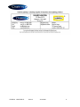
Type Of Protection LED
with Ex d switch
Ex e mb q (Increased safety, Encapsulation, Powder filing), Ex tb (dust).
Ex d e mb q
Protection Standards (IEC) EN 60079-0, (IEC) EN 60079-1, (IEC) EN 60079-5, ((IEC) EN 60079-7,
(IEC) EN 60079-18, (IEC) EN 60079-28, (IEC) EN 61241-1
Area Classification Zone 1 and Zone 2 areas to (IEC) EN 60079-10-1
Zone 21 and Zone 22 areas to (IEC) EN 60079-10-2
Installation (IEC) EN 60079-14
Certificate IECEx Certificate of Conformity IECEx BAS 09.0017
EU- Type Examination Certificate Baseefa04ATEX0220
Equipment Coding Ex e mb op is q IIC T4 Gb or Ex d e mb op is q IIC T4 Gb
Ex mb op is tb lllC T95°C Db IP6X -40°C Ta +55°C
Ex db e mb op is q IIC T4 Gb (fitted with Hawke CSPU stopping plug)
ATEX Coding II 2GD
Ingress Protection IP66/67 to EN(IEC) 60529
CE Mark
The CE marking of this product applies to "The Electrical Equipment (Safety) Regulations
2006", "The Electromagnetic Compatibility Regulations 2004", the “Waste Electrical and
Electronic Equipment Regulations 2006” and the "Equipment and Protective Systems intended
for use in Explosive Atmospheres Regulations 1996". [This legislation is the equivalent in UK
law of EU directives 2014/35/EU, 2014/30/EU, 2012/19/EU and 2014/34/EU respectively].
The Equipment is declared to meet the provisions of the ATEX directive (2014/34/EU)
by reason of the EU Type Examination and compliance with the Essential Health and
Safety Requirements.
M Poutney Technical Manager
1.0 Introduction – Protecta LED GRP ATEX and IECEx
This installation leaflet covers the range of ATEX and IECEx Protecta GRP luminaire models with the Ex q control gear.
These luminaires are mainly used in harsh environments and are constructed using a corrosion resistant glass reinforced
polyester body and polycarbonate diffuser. Refer to the current catalogue for information on product references. The
luminaires are available in 02L (2ft) and 05L (4ft) sizes.
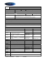
2.0 Electrical Supplies
Lamps 02L - 2 x 600mm LED Strip 05L - 2 x 1200mm LED Strip
Voltage range AC 110-130V or 220-254V
Frequency range Hz 47-63Hz
Power Watts 220-254V 32W 61W
Current Amps 220-254V 0.16
–
0.14A 0.29 - 0.25A
Power Watts 110-130V 32W 61W
Current Amps 110-130V 0.31 - 0.27A 0.59
–
0.50A
The safety limit for surface temperature (T rating) is +/-10% on the rated voltage. The maximum nominal variation from rated
voltages stated above is +/- 6%.
Power Factor >0.95 Power is constant over voltage range.
Over Voltage 400V ac for 1 min and EN 61000-4-5 > 4kV
Through Wiring The through current rating is 16A. 4mm² terminals are standard (6mm² wiring can be
used in the terminals in accordance with the luminaire certificate).
Fuse and MCB Ratings It is recommended that for selection of MCBs users should consult the MCB
manufacturer as this unit contains electronic control gear. The electronic control gear has
nominal values of inrush current of 35A for 70µs on 230V and 70A for 70µs on 110V.

I-PRGE-25 IOM PRGE LE Issue 12 31/03/2021 3
Storage Luminaires are to be stored in cool dry conditions preventing ingress of moisture and
condensation. Storage temperature range to be -40°C to +80°C.
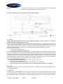
Typical wiring diagram shown for information only, some models may differ.
3.1 General
These instructions should be read fully and carefully before attempting to install the luminaire. For details of
servicing operations, opening etc. see section 4.0.
Copies of these instructions should be held in a safe place for future reference. It is the responsibility of the installer to
ensure that the apparatus selected is fit for its intended purpose and that the installation, operation and maintenance of the
apparatus complies with applicable regulations, standards or codes of practice. Installation should be carried out in
accordance with (IEC) EN 60079-14 or with a local hazardous area code of practice, whichever is appropriate.
Risk of electrostatic discharge:
Clean diffuser only with damp cloth
Avoid mounting near fast moving streams of air
Any specific installation instructions must be referred to. In the UK the requirements of the Health and Safety at Work Act
must be met and electrical work associated with this product must be in accordance with the "Manual Handling Operations
Regulations" and "Electricity at Works Regulations 1989". Disposal instructions should be complied with. The luminaires
should be considered Class 1 to EN 60598 and effectively earthed. Certification details on the rating plate must be verified
against the application requirements before installation. The information in this leaflet is correct at the time of publication.
The company reserves the right to make specification changes as required without notice.
3.1.1 Use in Combustible Dust Atmospheres
De-rating of the surface temperature will be required where dust clouds may be present
Do not allow dust to accumulate in layers
Dust in layers has the potential to form ignitable clouds and to burn at lower temperatures.
Refer to EN (IEC) 60079-10-2 & EN (IEC) 60079-14 for additional details of selection and installation.
3.2 Tools
3mm and 4mm flat blade screwdriver and large crosshead screwdriver. Suitable spanners for installing cable glands. Pliers,
knife, wire strippers/cutters.
3.3 Mounting
Luminaires should be installed where access for maintenance is practical and in accordance with lighting design information.
For horizontal mounting on handrails Chalmit recommend mounting the luminaire with the clamp bar uppermost therefore
allowing the diffuser and gear tray to swing down when necessary. Refer to the note in 3.1 concerning electrostatic charge.

I-PRGE-25 IOM PRGE LE Issue 12 31/03/2021 4
The standard suspension is via two M8 x 12mm deep blind tapped holes in stainless steel bushes in the top of the body, the
recommended torque for the fixing bolts is 10-15Nm. Various adaptors, pole clamps and suspension brackets are available to
order. The 2x18W, 2x36w models are available with integral side entry for 42 mm diameter poles.
3.4 Cabling and Cable Glands
The temperature conditions at the supply cable entry point are such that 70°C (ordinary PVC) cable can be used. Equipment
certified cable glands and sealing plugs must have suitable IECEx/ATEX approval. When installed the cable gland or sealing
plug should maintain the IP rating of the enclosure, IP66/67.
The pole mounted version has a cable gland fitted which will seal onto cables in the range 13 to 18 mm OD. The gland does
not have provision for armour clamping.
Four entries are provided. Three entries are fitted with suitably approved blanking plugs, the fourth entry with a transit plug.
M20 x 1.5 entries are standard, other sizes are available on request. The standard entry configuration is with an earthed
metal plate with tapped holes mounted in the body.
3.5 Electrical Connections and Testing
If any work is to be done on any luminaire already connected to the electrical system, the luminaire must be isolated from the
system. The diffuser cover is swung down and removed, if necessary, by swivelling back as far as possible then lifting off. To
access the mains terminals loosen the four fixing screws, slide the reflector/gear tray over the slots and swing the
reflector/gear tray down. Luminaires are supplied suitable for looping and through wiring. Screw type or screw-less “cage
clamp” terminals are fitted in the range of luminaires. Mains terminal blocks are marked L N Earth.
The maximum amount of insulation allowed beyond the throat of the terminal is 1mm. The normal method of insulation
testing is to connect Live and Neutral together and test between this point and Earth to prevent the risk of damage to the
electronic control gear. However, if this is not possible luminaires can be tested with an insulation tester that complies with
IEC 364 or BS 7671 with a maximum output current of 1mA and output voltage of 500V dc. (Units damaged by incorrect
insulation testing can be detected). Before completing the wiring, ensure that all the connections are correctly introduced into
place before reassembling the luminaire.
4.0 Servicing and Operation
Safe servicing behind the gear tray requires the mains supply to be isolated.
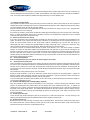
4.1 Opening and Closing the Cover
Insert a screwdriver into one of the slots in the clamping bar with the end of the tool located into the outer flange of the body
as a fulcrum point, a wide blade screwdriver is recommended. Gently lever the tool away from the diffuser, the clamping bar
will begin to open. Insert the tool in the other clamping bar slot and gently lever away from the diffuser, the clamping bar will
open and the cover will be retained by the hinge. Should difficulty be experienced reinsert the tool in the first slot and repeat
the procedure.
The procedure for closing and securing the cover is as follows:
Ensure the hinge mechanism is clear of any obstruction and then swing the diffuser into the closed position. Support the
diffuser in position whilst pushing the clamp bar over the edge of the diffuser. Apply even pressure at both ends of the bar
and press the bar over centre making sure that it goes fully into position.
To remove and replace the diffuser open the diffuser to 180° and it will lift out. When replacing ensure that all the hinges are
into place before attempting to close.
4.2 Removal and Replacement of Clamping Bar (if required)
Open the luminaire as above and remove the diffuser or let it swing down. Press the clamping bar towards the closed
position, tip forward beyond the closed position and the clamping bar will be released from the body. To replace the
clamping bar, put in position on the body with the front edge pointing as far inwards as it will go. Click the bar outwards and
bring back to the normal closed position. The clamping bar should then be secured in position, open the clamping bar fully
by using hand or screwdriver pressure (avoid damaging the gasket), the clamping bar is then ready to accept the normal
closure of the diffuser.
4.3 Releasing the Gear Tray
Loosen the four fixing screws retaining the gear tray far enough for it to slide over keyhole slots. The tray will hang on the
retaining cords without stressing the wiring between body and tray. Replace in reverse order.
4.4 Removal of Gear Tray
Release gear tray from body and hang on retaining cords, as explained above. Disconnect the cables from the gear tray to
the mains terminal block, unhook retaining cord from gear tray and lift clear. With disconnection made at the screw-less
terminals the luminaire is safe when re-closed without the tray.

I-PRGE-25 IOM PRGE LE Issue 12 31/03/2021 5
4.5 Servicing Behind the Gear Tray
The release of the gear tray exposes live mains terminals. Any work behind the gear tray requires that the supply is
isolated to avoid ignition risk and damage to components.
4.6 Replacement of LED Strips
Remove gear tray from the body and swing down as previously explained. Identify the wires for the LED strip/s and
disconnect from the terminal block. Remove screws and clips holding the strips in place. Replace strips using screws and
clips and reconnect to terminal block. Check connections before re-energising.
4.7 Replacement of Driver
The driver contains no serviceable parts. Should it be found necessary to replace the driver, the following procedure should
be adopted: Ensure that the luminaire is isolated from the mains supply.
Remove gear tray from body and swing down as previously explained. Disconnect the driver wires from the terminal blocks
(note the connections) and remove the driver from the tray.
5.0 Routine Maintenance
Visual tests and checks should be carried out at intervals described by the appropriate regulations, EN 60079-17, and should
include the following:
Check for mechanical damage/corrosion.
Check connections, fixings, glands and plugs.
Check for undue accumulations of dust, dirt or moisture.
Check for unauthorised modifications.
Periodic inspection of the enclosure seal should be carried out to ensure that the seal is sound. The seal can be replaced
and, if necessary, secured in position by the application of a very small amount of rubber adhesive and using the joining
piece. Care must be taken to ensure seal is not stretched during assembly. If the luminaire has been subject to abnormal
conditions, for example, severe mechanical impact or chemical spillage, it must be de-energised until it has been inspected
by an authorised and competent person
5.1 Cleaning
The body of the luminaire may be cleaned with a mild solution of household detergent and water, after cleaning the body
should be washed and wiped with clean water. The diffuser should not be polished or wiped with a dry cloth as a risk
of ignition due to electrostatic discharge may result. Cleaning of the diffuser with any chemical or hydrocarbon solvent
based cleaner may result in severe damage.
6.0 Disposal of Material
Disposal of the luminaire as waste should be carried out in accordance with national regulations. Any disposal must satisfy
the requirements of the WEEE directive [2012/19/EU] and therefore must not be treated as commercial waste. The unit is
mainly made from incombustible materials. The control gear contains plastic, resin and electronic components. All electrical
components may give off noxious fumes if incinerated.
To comply with the Waste Electrical and Electronic Equipment directive 2012/19/EU the
apparatus cannot be classified as commercial waste and as such must be disposed of or
rec
y
cled in such a manner as to reduce the environmental impact.

I-PRGE-25 IOM PRGE LE Issue 12 31/03/2021 6

I-PRGE-25 IOM PRGE LE Issue 12 31/03/2021 7
EU-Declaration of conformity
UE-Déclaration de conformité
EU-Konformitätserklärung
Manufacturer Chalmit Address 388 Hillin
g
ton Road, Glas
g
ow. G52 4BL Scotland UK
Product Protecta III GRP Fluorescent Luminaire
(
LED
)
EU - T
y
pe Examination Certi
f
icate Baseefa04ATEX0220
Notified Bod
y
SGS Fimko OY 0598
ATEX Coding II 2 GD ATEX Classification Group II Category 2 GD
Equipment Coding Ex e mb op is q IIC T4 Gb, Ex tb IIIC T95°C Db or Ex d e mb op is q IIC T4 Gb,
Ex mb op is tb IIIC T95°C Db IP6X -40°C Ta +55°C
Ex db e mb op is q IIC T4 Gb (fitted with Hawke CSPU stopping plug)
In
g
ress Protection IP66/67
The technical basis, with respect to equivalence of
La base technique, en ce qui concerne l'équivalence de
Die technische Grundla
g
e hinsichtlich der Normen
Protection Standards EN 60079-0, EN 60079-1, EN 60079-5, EN 60079-7, EN 60079-18, EN 60079-28, EN 61241-1
Area Classification EN 60079-10-1 and EN 60079-10-2
of compliance with the EHSRs is valid as there are no changes which materially affect the state of technological progress of the product.
en conformité avec les EESS est valide puisqu'il n'y a aucun changement qui affecte matériellement l'état de l'évolution technologique du
produit.
zur Erfüllun
g
der GSGA ist
g
e
g
eben, da keine Änderun
g
en erfol
g
t sind, die einen Einfluss auf den technischen Stand des Produkts haben.
Terms of the directive: Standard & Date Certified to Standards Date Declared to
Prescription de la directive: Standard & date certifiée à Normes date Déclaré
Bestimmungen der Richtlinie: Standard & Datum Zertifiziert
nach
Standards Datum erklärt
2014/34/EU Equipment and protective systems intended for use
in potentially explosive atmospheres.
EN 60079-0 : 2009 2012
EN 60079-1 : 2007 2014
2014/34/UE Appareils et les systèmes de protection destinés à
être utilisés en atmosphères potentiellement
explosibles.
EN 60079-5 : 2007
EN 60079-7 : 2007 2015
2015
2014/34/EU
Geräte und Schutzsysteme zur bestimmungs-
gemäßen Verwendung in explosionsfähigen
Bereichen.
EN 60079-18 : 2004
EN 60079-28: 2015
EN 61241 : 2004
2015
EN 60079-31 : 2014
2014/30/EU Electroma
g
netic compatibilit
y
EN 55015 : 2013
2014/30/UE Compatibilité électroma
g
nétique EN 61547 : 2009
2014/30/EU Elektromagnetische Verträglichkeit EN 61000-3-2 : 2014
2014/35/EU Low volta
g
e equipment EN 60598-1 : 2015
2014/35/UE Équipements électriques à bas voltage EN 60529 : 1992
2014/35/EU Niederspannun
g
s
g
eräte / -s
y
steme
2012/19/EU Waste of electrical and electronic equipment Shell Deluge DTS-01 : 1991
2012/19/UE Déchets d'équipements électriques et électroniques Seismic EN 60068-3-3 : 1993
2012/19/EU Entsorgung der elektrischen und elektronischen
Geräte / S
y
steme
Nuclear Seismic
IEC 60980-6 : 1993
2011/65/EU RoHS II Directive
Additional
information: The luminaire is capable of withstanding over voltage levels of up to 400V AC for 1 minute and impulse voltage surges
of 4kV.
Informations
complémentaires: Le luminaire peut supporter des niveaux de tensions juqu'à 400V CA pendant 1 minute et des tensions de choc de
4kV.

I-PRGE-25 IOM PRGE LE Issue 12 31/03/2021 8
Zusatzinformation
: Dieser Strahler widersteht Überspannungen bis 400V AC 1 Minute lang sowie Stoßspannungen von 4kV.
On behalf of the Chalmit, I declare that, on the date the equipment accompanied by this declaration is placed on the market, the equipment
conforms to all technical and regulatory requirements of the above listed directives.
En tant que représentant du fabricant Chalmit, je déclare qu'à la date où les équipements accompagnant cette déclaration sont mis sur le
marché, ceux-ci sont conformes à toutes les dispositions réglementaires et techniques des directives énumérées ci-dessus.
Hiermit bestätige ich, im Namen von Chalmit, dass am Tag der Lieferung des Produkts/der Produkte zusammen mit dieser Erklärung das
Gerät/die Geräte alle technischen und regulativen Anforderungen der oben aufgeführten Direktiven erfüllt.
Name and Date
Mark Poutney 31/03/2021
Technical Mana
g
er
Nom et Date Directeur technique
Name und Datum Technischer Leiter
Qualit
y
Assurance Notification b
y
:SGS Fimko OY Qualit
y
Mana
g
ement S
y
stem Acreditation: ISO 9001
Notification d'assurance qualité par: 0598 Certification du système de gestion de la qualité: by/par/durch
Qualitätssicherungsnotifikation durch: Qualitätsmanagementsystem Akkreditierung: Loyd's Register
Certificate No./Certificat N°/Zertifikat Nr. LRQ 4005876
-
 1
1
-
 2
2
-
 3
3
-
 4
4
-
 5
5
-
 6
6
-
 7
7
-
 8
8


Chalmit lighting I-PRGE-25 Guide d'installation
- Taper
- Guide d'installation
dans d''autres langues
Documents connexes
Autres documents
-
 Hadar Lighting HDN106 Guide d'installation
-
Raychem NGC-20-C(L)-E Guide d'installation
-
Eaton eLLB20 Fluorescent Mode d'emploi
-
-
Eaton eLLM 92 NE Operating Instructions Manual
-
Eaton GHG 511 Mode d'emploi
-
-
-
Eaton CROUSE-HINDS EXIT Series Operating Instructions Manual
-
