Extron Cable Cubby F55 Manuel utilisateur
- Catégorie
- Câbles de signal
- Taper
- Manuel utilisateur

1
IMPORTANT:
IMPORTANT:
Go to www.extron.com for the complete
user guide, installation instructions, and
specifications before connecting the
product to the power source.
Cable Cubby F55 • Installation Guide
This guide provides instructions for an experienced
technician to install and connect the Extron
Cable Cubby F55.
The Cable Cubby F55 is a lift-up cable access, furniture
mountable enclosure for AV connectivity, remote control,
and power. The lid lifts up to expose the connectivity
interface at a comfortable and ergonomic angle. When
closed, the Cable Cubby is nearly ush with the table
surface.
Planning the Installation
Check with local and state regulations
before starting the installation
• Ensure that the planned installation complies with
national and local building and electrical codes.
• Ensure that the planned installation complies with the Americans with Disabilities Act or other accessibility requirements.
Check All Parts and Equipment
• Ensure that all parts are present in each kit.
• Ensure that necessary tools and equipment are available for the installation.
Kit contents
Flex55 Adapter Module (2)
Grommet
Plugs (8)
Zip Ties (4)
Pry Tool (2)
Cable Grommet
Plate (2)
Cable Cubby F55
Optional Accessories
Tweeker
#10-32 Screws (4)
ZipClip 100 ZipClip 200
ZipClip 400
Figure 1. Cable Cubby F55 Kit Contents
USB CHARGER 120V 50-60Hz 12A MAX
~
1

2
Cable Cubby F55 • Installation Guide (Continued)
Application diagram
The application diagram below shows a power, data, and video wiring setup from a laptop to a conference monitor.
Q4 Sales by Region
Northwest
Northeast
Southwest
Southeast
Central
Extron
Cable Cubby F55
Furniture Mountable
Cable Access Enclosure
USB CHARGER 120 V 50-60Hz 12A MAX
~
USB CHARGER 120V 50-60Hz 12A MAX
~
Power
HDMI
Q4 Sales by Region
Northwest
Northeast
Southwest
Southeast
Central
Figure 2. Application Example Using the Cable Cubby F55 Enclosure
Preparing the Table
Determine the Best Location for the Enclosure
• Ensure that the location where the Cable Cubby is to be installed is convenient for as many users as possible.
• Ensure that the edge on which the lid opens is oriented correctly.
• Ensure that there is ample space under the table for cables. Allow at least 36 inches of cable loop for each cable (see
Routing and Managing Cables on page8).
CAUTION: The anged edges of the top of the surface enclosure are sharp. These edges are also soft and may be easily
nicked or bent. Exercise caution when handling the enclosure to prevent personal injury or damage to the enclosure.
ATTENTION : Les extrémités à brides du haut de la surface du boîtier sont aiguisées. Ces extrémités sont aussi lisses et
peuvent facilement être coupées ou pliées. Soyez prudents lorsque vous manipulez le boîtier an d’éviter de l’endommager
ou de vous blesser.
2

3
Cut a Hole in the Table
Read the following information before making a cut in the table.
CAUTION: Wear safety glasses when operating power equipment. Failure to comply can result in eye injury.
ATTENTION : Portez des lunettes de sécurité lorsque vous utilisez l’équipement électrique. Ne pas respecter cela peut
conduire à une blessure à l’oeil.
ATTENTION: The opening in the table for the Cable Cubby should be cut only by licensed and bonded craftspeople.
Exercise care to prevent scarring or damaging the furniture.
ATTENTION : L’ouverture dans la table pour le CableCubby devrait être coupée seulement par des artisans autorisés et
qualifiés. Faites attention à ne pas faire de marques sur le meuble et à ne pas l’endommager.
1. Choose one of the following methods for cutting the hole:
Hand Router and Routing Template Jigsaw and Paper Cut-Out Template CNC Wood Router
Cut-Out Template for the Extron
Cable Cubby F55
Outer Edge of Front Bezel
(Do not cut this line.)
1. Confirm the product to be installed.
2. Remove the surface cut-out area
(gray) from the template.
3. Measure the cutout and template.
4. Mark the position on the
furniture where the Cable Cubby 1200
will be installed.
5. Double check the dimensions and position,
then cut the opening.
Trim Ring
Lip
Cut-Out Radius:
0.25" (0.6 cm)
User Access
P/N 68-3772-01 Rev. A
Page Size: 11" x 17"
Print Scale 1:1
Do not Shrink
If using a CNC wood router or other
precise machinery, use the exact
cut-out dimensions (see the table below).
Cut-out Dimensions
User Access
Width
Side
Dimension
Cable
Cubby
F55
10.50"
(267 mm)
6.00"
(152 mm)
Go to www.extron.com for routing
template part numbers and instructions.
Dimensions and cut-out templates are
available online at www.extron.com.
2. Measure and cut the hole in the surface where the enclosure will be installed.
Installing the Modules into the Cable Cubby F55 Enclosure
The Cable Cubby F55 enclosure supports Flex55 and EU modules, which can be installed in a variety of combinations. These
modules can be installed either before or after the Cable Cubby F55 installation, in any slot of the enclosure. Determine where the
connectivity modules and power module will be installed in the enclosure.
NOTE: For a complete and up-to-date list of compatible modules, see the product page at www.extron.com.
Figure 3 shows the process for removing the supports in order to install a double-size module, such as the Flex55 AC+USB 130
US Power Module, into the Cable Cubby F55 enclosure. Half- and full-size modules can be snapped into the enclosure without
removing the supports (1).
1
Extron Cable Cubby F55
Enclosure
For a double-size module
installation, use pliers to
carefully twist the desired
support back and forth until
loose, and remove.
NOTE: Removal of a bridge support
is irreversible.
Figure 3. Removing a Support for a Double-sized Flex55 Module Installation
3

4
Snap the grommet plate
into the Adapter Module.
b
b
b
Snap included grommet plugs
into any unused holes in the
grommet plate.
d
Install the cable grommet plate for cable pass-through applications.
For cable pass-through installation,
insert the cables through the bottom
of the Cable Cubby F55, through the
Cable Cubby F55 Adapter Module, and
then through the holes of the gr
ommet plate.
a
a
a
2
Align the adapter module with
an opening in the Cable Cubby F55
frame and then snap it into place
in the enclosure.
c
Figure 4. Setting Up the Cable Grommet Plate
Plug in any additional
devices here.
Connect to
power source.
USB CHARGER
~
120V 50-60Hz 6A MAX
3
3
3Feed the cables through the
Cable Cubby F55 enclosure
for the Flex55 and EU modules
being installed. Attach the
cables to the modules before
snapping the modules into place.
4
4
4Insert the modules (in this
example, the double-size
Flex55 AC+USB 130 US),
into the opening and snap
them into the frame.
Figure 5. Installing Flex55 and EU Modules into the Cable Cubby F55 Enclosure
4

5
Cable Cubby F55 • Installation Guide (Continued)
Attaching an Optional ZipClip Mounting Device to the Cable Cubby F55
The ZipClip 100, 200, or 400 can be attached to the Cable Cubby F55 with the included #10-32 screws, in order to mount a
power supply or other device to the enclosure. Determine which ZipClip to use, and ensure there is ample space for the device
and its cables.
NOTE: All ZipClips must be mounted with horizontal orientation.
ZipClip 100
ZipClip 200
ZipClip 400
Figure 6. Mounting a ZipClip to the Cable Cubby F55 Enclosure
5

6
Cable Cubby F55 • Installation Guide (Continued)
Mounting the Cable Cubby F55 in the Table
Step 1 — Mount the Cable Cubby Flush with the Table
Lower the Cable Cubby into
the hole to test the t.
If necessary, carefully enlarge
the opening.
2
After the enclosure is lowered
and resting in the table, remove
the plastic strips and lm on the
surface of the Cable Cubby.
3
2
Ensure the side clamps are
seated against the enclosure
and positioned on the lower
part of the shaft.
1
USB CHARGER 120V 50-60Hz 12A MAX
~
Figure 7. Mounting the Cable Cubby F55 to a Table
6

7
Cable Cubby F55 • Installation Guide (Continued)
Step 2 — Under the Table, Adjust the Side Clamps on the Enclosure
Rotate the side clamp
outward and ensure that
the lever is down.
Slide the clamp all the
way up against the bottom
of the table.
Ensure the Cable Cubby
is rmly seated in the table.
Raise the lever to secure
the Cable Cubby.
Lever
2
13
USB CHARGER 120V 50-60Hz 12A MAX
~
Figure 8. Adjusting and Securing the Side Clamps
7

8
Cable Cubby F55 • Installation Guide (Continued)
Routing and Managing Cables
Organize and connect cables as shown in gure8. Use zip ties (provided) to fasten the cables to the enclosure where needed.
USB CHA RGER 120V 50-60 Hz 12A M AX
~
Manage the cables with the lid
in the fully open position.
1
For cable pass-thr
ough applications,
allow at least 36 inches (914 mm) of
cable loop for each cable.
2
3Manage cables for xed modules
by zip-tying the cables to the
bottom of the unit.
Give a generous cable loop to allow
the lid to open and close without restrictions.
Raise and lower the lid again after cabling is installed
to ensure the lid operates as desired. Provide more loop
in the cabling if necessary and re-secure to the enclosure.
4
Figure 9. Routing and Managing the Cables
8

9
Cable Cubby F55 • Installation Guide (Continued)
Appendix
Removing Flex55 and EU Modules from the Cable Cubby F55
If the modules need to be replaced or removed from the Cable Cubby F55 enclosure, the following diagrams show the procedure for
removing modules with the provided pry tools. This process applies to any compatible Flex55 and EU module.
USB CHARGER 120V 50-60Hz 12A MAX
~
USB CHARGER 120V 50-60Hz 12A MAX
~
Insert the pry tools
at the locking
tab locations.
2
Locking Tabs
Pull the pry tools away from
the module to unhook the
locking tabs from the
mounting frame.
3Ensure the cabling is detached from
the enclosure and from any other
cabling before r
emoving the module.
1
4
Repeat steps 1 through 3 on the other side of the module.
Figure 10. Removing a Double Module
USB CHARGER 120V 50-60Hz 12A MAX
~
Locking
Tabs
Insert the pry tool
at the locking tab
location.
1
Figure 11. Removing Flex55 and EU Modules
NOTE: To verify the location
of the locking tabs,
check the module
specifications (available
at www.extron.com).
9
10

10
Cable Cubby F55 • Installation Guide (Continued)
Removing the Enclosure from the Table
To remove the Cable Cubby F55 enclosure from its mounting location in the table, release the side clamps as shown below:
NOTE: When the clamps cannot be loosened by hand, an Extron Tweeker or other small screwdriver may be necessary to
help with leverage.
1
1
1
2
2
23
3
3
Insert a Tweeker or small
screwdriver into the slot
of the clamp lever.
Tilt the Tweeker or
screwdriver downwards,
away from the table, to
release the clamp.
Remove the Tweeker. Rotate and
push the clamp assembly against
the enclosure for the enclosure to
clear the opening when removing
the Cable Cubby F55 fr
om the table.
Figure 12. Removing the Cable Cubby F55 Enclosure from the Table
11

11
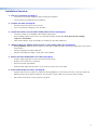
Installation Overview
1. Plan the installation (see page 1).
• Check with local and state regulations before starting the installation.
• Check all parts and equipment before installation.
2. Prepare the table (see page 2).
• Determine the best location for the enclosure.
• Choose a method for cutting the hole in the table.
3. Install the modules into the Cable Cubby F55 enclosure (see page 3).
• Check the modules for compatibility and installation requirements.
• Remove bridge supports if necessary to accommodate a double-sized module. Note that removal of bridge
supports is irreversible.
• Cable and install half-, single- and double-size modules into the Cable Cubby F55.
4. (Optional) Attach a ZipClip mounting device to the Cable Cubby F55 (see page 5).
• If using a ZipClip, determine which model to use (100, 200, or 400). Plan and ensure there is ample space for the device
and its cables.
• Attach the ZipClip to the Cable Cubby F55.
• Attach the desired power supply or other device to the ZipClip.
5. Mount the Cable Cubby F55 in the table (see page 6).
• Seat the clamps against the enclosure and in the lowest position.
• Drop the enclosure into the cut opening.
• Remove the plastic strip and film.
• Under the table, adjust the side clamps on the enclosure, and secure it to the table.
6. Route and manage the cables (see page8).
• Organize and connect the cables. For cable pass-through applications, allow at least 36 inches (1 meter) of cable loop.
• With the lid open, allow sufficient cable loop. Use tie wraps to attach cables to the enclosure where needed.
• Raise and lower the lid to ensure it operates as desired.

12
68-3527-50 Rev. A
04 23
© 2023 Extron Electronics — All rights reserved. www.extron.com
All trademarks mentioned are the property of their respective owners.
Worldwide Headquarters: Extron USA West, 1025 E. Ball Road, Anaheim, CA 92805, 800.633.9876
For information on safety guidelines, regulatory compliances, EMI/EMF compatibility, accessibility, and related topics, see the
Extron Safety and Regulatory Compliance Guide on the Extron website.
-
 1
1
-
 2
2
-
 3
3
-
 4
4
-
 5
5
-
 6
6
-
 7
7
-
 8
8
-
 9
9
-
 10
10
-
 11
11
-
 12
12


Extron Cable Cubby F55 Manuel utilisateur
- Catégorie
- Câbles de signal
- Taper
- Manuel utilisateur
dans d''autres langues
- English: Extron Cable Cubby F55 User manual
Documents connexes
-
Extron NBP 100 Manuel utilisateur
-
Extron Cable Cubby 1252 M Manuel utilisateur
-
Extron TLP Pro 720C Manuel utilisateur
-
Extron TouchLink TLP Pro 725C Series Manuel utilisateur
-
-
-
Extron TouchLink TLE 350 Manuel utilisateur
-
-
-