
04/15 2015 JM HEAT STAR, Inc., 4560 W. 160TH ST., CLEVELAND, OHIO 44135 • 866-447-2194
WARNING:
· Do not store or use gasoline or other flammable vapors and liquids in the vicinity of this or any
other appliance.
· An LP cylinder not connected for use shall not be stored in the vicinity of this or any other
appliance.
· WHAT TO DO IF YOU SMELL GAS
• Do not try to light appliance.
• Extinguish any open flame.
• Shut off gas to appliance.
· Service must be performed by a qualified service agency.
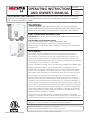
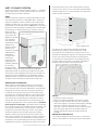
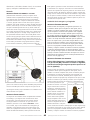
This is an un-vented gas-fired portable heater. It uses air (oxygen) from the area in which it is used.
Adequate combustion and ventilation must be provided. Refer to pages 4 & 5.
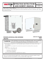
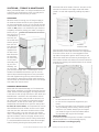
FORCED AIR DUAL-FUEL NOMAD
HEATER
If the information in this manual is not followed exactly, a fire or explosion
may result, causing property damage, personal injury or loss of life.
HS115TC
HS190TC
HS250TC
OPERATING INSTRUCTIONS
AND OWNER’S MANUAL
READ INSTRUCTIONS CAREFULLY: Read and follow all instructions. Place instructions in a safe place
for future reference. Do not allow anyone who has not read these instructions to assemble, light, adjust
or operate the heater.
Model #
LANGUAGES INCLUDED
•ENGLISH
•FRENCH
•SPANISH

2
Forced-Air Dual-Fuel NOMAD Construction Heater Operating Instructions and OwnerÊs Manual
CONTENTS
WARNINGS ..........................................................................2
SPECIFICATIONS ...................................................................3
OPERATING PRECAUTIONS ..................................................4
SAFETY PRECAUTIONS .........................................................4
ODOR FADE WARNING ........................................................5
ASSEMBLY AND PREPARATION FOR OPERATION ..................6
HOSE AND REGULATOR INFORMATION ...............................6
FUEL AND RATE SELECTION .................................................7
OPERATION .........................................................................7
USING THE ACCESSORIES ...................................................8
SHUT DOWN AND STORAGE ...............................................9
MAINTENANCE ....................................................................9
PROPANE TANK SIZE SELECTION ........................................10
TROUBLESHOOTING .......................................................... 11
WIRING DIAGRAM ............................................................. 12
PARTS LISTS AND EXPLODED VIEWS .................................. 13
WARRANTY INFORMATION ...............................................20
WARNING:
FIRE, BURN, INHALATION, AND EXPLOSION HAZARD.
KEEP SOLID COMBUSTIBLES, SUCH AS BUILDING
MATERIALS, PAPER OR CARDBOARD, A SAFE DISTANCE
AWAY FROM THE HEATER AS RECOMMENDED BY THE
INSTRUCTIONS. NEVER USE THE HEATER IN SPACES
WHICH DO OR MAY CONTAIN VOLATILE OR AIRBORNE
COMBUSTIBLES, OR PRODUCTS SUCH AS GASOLINE,
SOLVENTS, PAINT THINNER, DUST PARTICLES OR UN-
KNOWN CHEMICALS.
WARNING:
NOT FOR HOME OR RECREATIONAL VEHICLE USE
WARNING:
YOUR SAFETY IS IMPORTANT TO YOU AND TO OTHERS,
SO PLEASE READ THESE INSTRUCTIONS BEFORE YOU
OPERATE THIS HEATER.
GENERAL HAZARD WARNING:
FAILURE TO COMPLY WITH THE PRECAUTIONS AND
INSTRUCTIONS PROVIDED WITH THIS HEATER, CAN
RESULT IN DEATH, SERIOUS BODILY INJURY AND
PROPERTY LOSS OR DAMAGE FROM HAZARDS OF FIRE,
EXPLOSION, BURN, ASPHYXIATION, CARBON MONOX-
IDE POISONING, AND/OR ELECTRICAL SHOCK.
ONLY PERSONS WHO CAN UNDERSTAND AND FOLLOW
THE INSTRUCTIONS SHOULD USE OR SERVICE THIS
HEATER.
IF YOU NEED ASSISTANCE OR HEATER INFORMATION
SUCH AS AN INSTRUCTIONS MANUAL, LABELS, ETC.
CONTACT THE MANUFACTURER.
THE STATE OF CALIFORNIA REQUIRES THE FOLLOWING WARNINGS:
WARNING: Combustion by-products produced when using this product contain carbon monoxide, a chemical
known to the State of California to cause cancer and birth defects (or other reproductive harm).
WARNING: This product contains chemicals known to the State of California to cause cancer and birth defects
or other reproductive harm.
This NOMAD Forced Air Duel-fuel construction
heater was Assembled in the U.S.A. by:
Enerco Group Inc. 4560 West 160th Street
Cleveland, Ohio 44135
For Questions and Inquiries Contact us at:
CALL: 866-447-2194
FAX: 800-321-0552
VISIT: HEATSTARBYENERCO.COM.
Office hours are:
Monday - Friday 8:00am - 5:00pm

Operating Instructions and OwnerÊs Manual
3
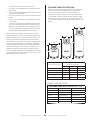
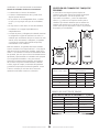
Forced-Air Dual-Fuel NOMAD Construction Heater
MODEL# (Stock#) HS115TC (F109100) HS190TC (F109110) HS250TC (F109120)
PROPANE BTU/kW INPUT
HIGH LP (kW) 110,833 BTU/HR (32kW) 190,200 BTU/HR (56kW) 248,625 BTU/HR (73kW)
LOW LP (kW) 80,612 BTU/HR (24kW) 127,100 BTU/HR (37kW) 181,119 BTU/HR (53kW)
HIGH NG (kW) 107,586 BTU/HR (32kW) 183,600 BTU/HR (54kW) 248,625 BTU/HR (73kW)
LOW NG(kW) 77,124 BTU/HR (23kW) 128,700 BTU/HR (38kW) 172,252 BTU/HR (50kW)
OPERATINGS GAS PRESSURES (W.C./kPa)
MAX IN-LP TANK PRESSURE TANK PRESSURE TANK PRESSURE
MAX IN-NG (Kpa) 14" W.C. (3.49 Kpa) 14" W.C. (3.49 Kpa) 14" W.C. (3.49 Kpa)
MIN IN-LP (Kpa) 15 PSI (103.4 Kpa) 15 PSI (103.4 Kpa) 15 PSI (103.4Kpa)
MIN IN-NG (Kpa) 7" W.C. (1.74 Kpa) 7" W.C. (1.74 Kpa) 7" W.C. (1.74 Kpa)
MANIFOLD PRESSURE 4" W.C. (.99 Kpa) 4" W.C. (.99 Kpa) 4" W.C. (.99 Kpa)
FUEL CONSUMPTION PER HOUR
LP-HIGH LBS (Kg) 5.326 LBS/HR (2.41 Kg) 8.8 LBS/HR (3.99Kg) 12.042 LBS/HR (5.46 Kg)
LP-LOW LBS (Kg) 3.937 LBS/HR (1.78 Kg) 6.253 LBS/HR (2.83 Kg) 8.568 LB/HR (3.88 Kg)
NG-HIGH MCF .110 MCF .185 MCF .240 MCF
NG-LOW MCF .08 MCF .130 MCF .175 MCF
ELECTRICAL SPECIFICATIONS
ELEC. SUPPLY
(VOLTS/Hz/PHASE) 115V-60HZ- 1Ø 115V-60HZ-1Ø 115V-60HZ-1Ø
CONTINUOUS AMPS 3.5 AMPS 5.5 AMPS 8 AMPS
MOTOR H.P. 1/3HP 1/2HP 3/4HP
MOTOR WATTS 220 W 500 W 800 W
MOTOR R.P.M. 1100 1100 1035
HEATER DIMENSIONS/WEIGHTS
HEATER WEIGHT 91 LBS (40.3KG) 159 LBS (72 KG) 165 LBS (75 KG)
HEATER DIMENSIONS
(LxWxH)
30" x 23.75" x 15" 35.75" x 34.75" x 20.25" 35.75" x 34.75" x 20.25"
CARTON WEIGHT
(LBS/K.G.)
102 LBS (46.3KG) 176 LBS (79.8 KG) 182 LBS (83 KG)
CARTON DIMENSIONS
(LxWxH)
34.5" x 25.75" x 20" 39" x 36.75" x 24.25" 39" x 36.75" x 24.25"
SPECIFICATIONS
TOP SIDES BACK OUTLET
HS115TC 1' 1' 1' 6'
HS190TC 1' 1' 1' 6'
HS250TC 1' 1' 1' 6'
CLEARANCE TO COMBUSTIBLES

4
Forced-Air Dual-Fuel NOMAD Construction Heater Operating Instructions and OwnerÊs Manual
OPERATING PRECAUTIONS
This is a propane or natural gas, direct-fired, forced air
heater. It's intended use is primarily temporary heating of
buildings under construction, alteration or repair.
Propane is heavier than air. If the fuel leaks from a
connection or fitting, it sinks to the floor, collecting there
with the surrounding air, forming a potentially explosive
mixture. Obviously, fuel leaks should be avoided, so set up
the fuel supply with utmost care. Read the Odor Fade and
Propane warnings included in this manual for additional
information about detecting gas leaks. Leak check new
connections or re-connections with a soap and water
solution and follow all connection instructions herein. Also,
ask your propane dealer or natural gas supply company for
advice on the heater application and supply installation and
ask him to check it if there are any questions.
This heater was designed and certified for use as a
construction heater in accordance with ANSI Standard
Z83.7/CSA 2.14. Check with your local fire safety authority
if you have any questions about your applications. Other
standards govern the use of fuel gases and heat producing
products in specific applications. Your local authority can
advise you about these.
Direct-Fired means that all of the combustion products enter
the heated space. Even though this heater operates very
close to 100 percent combustion efficiency, it still produces
small amounts of carbon monoxide. Carbon monoxide
(called CO) is toxic. We can tolerate small amounts but not a
lot. CO can build up in a heated space and failure to provide
adequate ventilation could result in death. The symptoms of
inadequate ventilation are:
• headache
• dizziness
• burning eyes and nose
• nausea
• dry mouth or sore throat
So, be sure to follow advice about ventilation in these
operating instructions.
Forced Air means that a blower or fan pushes the air
through the heater. Proper combustion depends upon this
air flow; therefore, the heater must not be revised, modified
or operated with parts removed or missing. Likewise, safety
systems must not be circumvented or modified in order to
operate the heater.
When the heater is to be operated in the presence of other
people the user is responsible for properly acquainting those
present with the safety precautions and instructions, and of
the hazards involved.
SAFETY PRECAUTIONS
1. Check the heater thoroughly for damage. DO NOT
operate a damaged heater.
2. DO NOT modify the heater or operate a heater which has
been modified from its original condition.
3. Use only fuel types for which the heater has been
certified.
4. If using propane use only VAPOR WITHDRAWAL type
propane supply. If there is any question about vapor
withdrawal, ask your propane dealer.
5. Mount the propane cylinders vertically (shutoff valve
up). Secure them from falling or being knocked over and
protect them from damage.
6. Locate propane containers at least (USA) 7 ft. (2.13m),
(Canada) 10 ft. (3m) from the heater and do not direct
exhaust toward containers.
7. IMPORTANT Use only the hose and regulator assembly
provided with the heater. Inspect hose assembly before
each use of the heater. If there is excessive abrasion or
wear, or hose is cut, replace with hose assembly listed on
parts list in this manual before using heater.
8. For indoor or outdoor use where adequate ventilation has
been provided. Minimum openings of 1/2 sq. ft. (.046
m²) near the floor and 1/2 sq. ft. (.046 m²) near the
ceiling (also see "Operating Precautions").
9. If at any time gas odor is detected, IMMEDIATELY
DISCONTINUE operation until the source of gas has been
located and corrected. Read enclosed Odor fade and
Propane information for additional information about
detecting propane or natural gas leaks.
10. While this heater is designed to withstand a reasonable
about of harsh weather. It is best to install the heater such
that it is not directly exposed to water spray, rain and/or
dripping water.
11. Maintain minimum clearance from normal combustible
material like paper, canvas, plastic tarpaulins or similar
coverings and secure them to prevent flapping or
movement due to wind action.
12. Due to the high surface and exhaust temperatures, adults
and children must observe clearances to avoid burns or
clothing ignition.
13. Operate only on a stable, level surface.
14. For use with only approved duct lengths and materials.
15. Use only the electrical power specified. The electrical
connection and grounding must comply with National
Electrical Code - ANSI/NFPA 70 (USA) and CSA C22.1
Canadian Electrical Code, Part 1 (Canada).
16. Use only a properly grounded 3-prong receptacle or
extension cord (6 ft (1.83m) in length minimum).
17. Do not move, handle or service while hot or burning.
18. Use only in accordance with local codes or, in the absence
of local codes, with the Standard for the Storage and
Handling of Liquefied Petroleum Gases ANSI/NFPA 58 and
CSA B149.1, Natural Gas and Propane Installation Code.

Operating Instructions and OwnerÊs Manual
5
Forced-Air Dual-Fuel NOMAD Construction Heater
FUEL GAS ODOR
LP gas and natural gas have man-made odorants
added specifically for detection of fuel gas leaks.
If a gas leak occurs you should be able to smell
the fuel gas. Since these fuels are heavier than air
you should smell for the gas odor low to the floor.
ANY GAS ODOR IS YOUR SIGNAL TO GO INTO
IMMEDIATE ACTION!
• Do not take any action that could ignite the fuel gas.
Do not operate any electrical switches. Do not pull
any power supply or extension cords. Do not light
matches or any other source of flame. Do not use your
telephone.
• Get everyone out of the building and away from the
area immediately.
• Close all propane (LP) gas tank or cylinder fuel supply
valves, or the main fuel supply valve located at the
meter if you use natural gas.
• Propane (LP) gas is heavier than air and may settle in
low areas. When you have reason to suspect a propane
leak, keep out of all low areas.
• Use your neighborÊs phone and call your fuel gas
supplier and your fire department. Do not re-enter the
building or area.
• Stay out of the building and away from the area until
declared safe by the firefighters and your fuel gas
supplier.
• FINALLY, let the fuel gas service person and the
firefighters check for escaped gas. Have them air out
the building and area before you return. Properly
trained service people must repair any leaks, check for
further leakages, and then relight the appliance for
you.
ODOR FADING - NO ODOR DETECTED
• Some people cannot smell well. Some people cannot
smell the odor of the man-made chemical added to
propane (LP) or natural gas. You must determine if you
can smell the odorant in these fuel gases.
• Learn to recognize the odor of propane (LP) gas
and natural gas. Local propane (LP) gas dealers will
be more than happy to give you a scratch and sniff
pamphlet. Use it to become familiar with the fuel gas
odor.
• Smoking can decrease your ability to smell. Being
around an odor for a period of time can affect your
sensitivity to that particular odor. Odors present in
animal confinement buildings can mask fuel gas odor.
• The odorant in propane (LP) gas and natural gas
is colorless and the intensity of its odor can fade
under some circumstances.
• If there is an underground leak, the movement of gas
through the soil can filter the odorant.
• Propane (LP) gas odor may differ in intensity at
different levels. Since Propane (LP) gas is heavier than
air, there may be more odor at lower levels.
• Always be sensitive to the slightest gas odor. If
you continue to detect any gas odor, no matter how
small, treat it as a serious leak. Immediately go into
action as discussed previously.
ATTENTION- CRITICAL POINTS TO REMEMBER
• Propane (LP) gas has a distinctive odor. Learn to
recognize these odors. (Reference Fuel Gas Odor and
Odor Fading sections above.
• Even If you are not properly trained in the service and
repair of the heater, ALWAYS be consciously aware of
the odors of propane (LP) gas and natural gas.
• If you have not been properly trained in repair and
service of propane (LP) gas then do not attempt to
light heater, perform service or repairs, or make any
adjustments to the heater on the propane (LP) gas fuel
system.
• A periodic sniff test around the heater or at the
heaterÊs joints; i.e. hose, connections, etc., is a good
safety practice under any conditions. If you smell even
a small amount of gas, CONTACT YOUR FUEL GAS
SUPPLIER IMMEDIATELY. DO NOT WAIT!
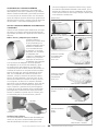
UNPACKING (Tools needed: Box cutter)
Remove heater and all components from cardboard
container. Thoroughly inspect all packing material for
pieces that are not garbage. Next check the unit for
possible shipping damage. If any is found immediately
notify the factory.
ODOR FADE WARNING
WARNING- ASPHYXIATION HAZARD
Do not use this heater for heating human living quarters.
• Do not use in unventilated areas.
• The flow of combustion and ventilation air must not be obstructed.
• Proper ventilation air must be provided to support the combustion air requirements of the heater being used.
• Refer to the specification section of the heaterÊs manual, heater data-plate, or contact the Factory to determine
combustion air ventilation requirements of the heater.
• Lack of proper ventilation air will lead to improper combustion.
• Improper combustion can lead to carbon monoxide poisoning leading to serious injury or death. Symptom of carbon
monoxide poisoning can include headaches dizziness and difficulty in breathing.

6
Forced-Air Dual-Fuel NOMAD Construction Heater Operating Instructions and OwnerÊs Manual
Assembly
INSTALLING THE WHEELS & FOOT (Tools needed: Pliers)
Most units will be completely assembled. However if for
any reason you do need to assemble these components
follow the these instructions. Using the cardboard that
your heater was shipped in turn your heater on to one
of it sides or its top so that the bottom of the heater is
accessible. First, take the axel and insert it into one of the
wheels supplied. Then on the outside of the wheel place
the large washer over the axle. You can then insert one
of the cotter pins into the hole in the end of the axle and
bend over one or both of the tails of the pin so that it
cannot be removed. Then on the inside of that wheel run
one of the spacers over the other end of the axel so that
it is pressed against the back of the wheel. Then slide the
axle into the holes along the bottom edge of the heater.
Then install the other spacer followed by the other wheel
and washer. You can then insert and bend the other
cotter pin. Finally you can press the rubber hub caps over
the end of the axle. It is designed to press over the washer
to hold the cap in place once you are sure you have the
wheels and axle installed on your heater in the order
shown in figure 1.
INSTALLING THE HANDLE
Most units will be completely assembled. However if for
any reason you do need to assemble these components
follow the these instructions. First locate the metal "U"
shaped handle that was packed with your heater. (Does
not apply to model # HS115TC, If this is your model
move to hose and regulator setup). Next locate the two
handle bolts included in your hardware package. Then,
while looking at the outlet side of the heater open the
access panel opposite the control panel side by removing
the screws that hold it in place around its perimeter. Just
above the top edge of the door opening you should see
two holes close to the top edge of the heater. Align the threaded
holes in the handle up to the holes in the cover of the heater.
Then thread the two supplied bolts through the case into the
handle from inside of the case. Using a socket wrench tighten
down the bolts. Be sure not to over tighten.
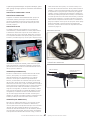
Hose and Regulator setup
SETUP FOR PROPANE
First locate the hose and regulator assembly included with
your heater. Inspect the hose for cracks, breaks and any
signs of damage. If any damage is found, contact the factory
for a replacement. The regulator end is equipped with a
standard POL connection designed to fit most vertical vapor
draw propane tanks. Note: This is a reverse "left hand"
thread. Next attach the P.O.L. to an appropriately sized tank
for your application. This is a flared fitting and this type of
connection does not require any additional sealant or thread
tape. Check all connections with a mixture of soap and
water for leaks. Mix water and a small amount of dish soap
in a spray bottle and apply the solution on all connections, looking
for small bubbles to appear. If you see bubbles that is an indication
of a leak. Tighten your connection until the bubble are eliminated.
For proper tank sizing, refer to the sizing chart in the trouble
shooting section of this manual. (page 10)
SETUP FOR NATURAL GAS.
You must first determine if a regulator will be
required. When using NG a regulator will only be
required when the source of the gas has an output
pressure greater than 14" w.c. (3.48 Kpa).
First locate the hose and regulator assembly included with
your heater. Inspect the hose for any cracks breaks or signs
of damage. If any damage is found, contact the factory
for a replacement. The regulator end is equipped with
a standard POL connection designed to fit most vertical
vapor draw propane tanks. If you are using your unit with
Natural Gas and you have determined the regulator will
be needed, first the "P.O.L. fitting will have to be removed
and replaced with a connector/connectors that will allow
for connection to your Natural Gas supply. To remove the
P.O.L. fitting, secure the regulator body in a vice being
careful not to damage it. Then
using a socket wrench remove
he P.O.L. stem and nut from the
regulator. Then replace the POL
with the appropriate pieces to
make your connection. Be sure
to use an appropriate sealant
or thread tape when required.
Check all connections with a
mixture of soap and water for
leaks. Mix water and a small
amount of dish soap in a spray
bottle and apply the solution on
all connections, looking for small
bubbles to appear. If you see bubbles that is an indication
of a leak. Tighten your connection until the bubble are
eliminated.
1
2
3
5
2
3
4
4
# DESCRIPTION QTY
1 WHEELS 2
2 COTTER PINS 2
3 RETAINER WASHERS 2
4 WHEEL SPACERS 2
5 AXLE 1
FIGURE 1
POL
Remove for NG installation

Operating Instructions and OwnerÊs Manual
7
Forced-Air Dual-Fuel NOMAD Construction Heater
power switch). The male plug end of the heater will
go inside the female receptacle on the thermostat plug
end. Next plug in your properly grounded three pronged
extension cord into the other side of the thermostat
plug. You can now switch on your heater and return to
where you have your thermostat located and set the
temperature at which you would like your heater to cycle
on and off at. Once the temperature in the space to be
heated drops below the point at which your thermostat
is set, the green indicator light above the switch will
illuminate and the heat sequence will begin. The unit
will continue to run until the setting of the thermostat
is satisfied. If your heater shuts down for any reason
other than the operator turns it off or the thermostat
is satisfied, refer to the troubleshooting portion of this
manual on page 11.
RATE AND FUEL SELECTION
FUEL SELECTION
When setting up your Nomad heater you will need to
know which fuel you will be using and move the Rate/
Fuel selector switch to the correct settings before use. For
LP you will use the Red settings and rate. For NG you will
use the Blue settings and rates Refer to figure 5.
RATE SELECTION
Your Nomad heater is equipped with multi-rate and dual
fuel technology. During setup of your area to be heated
you have the option to use the heater on either the high
or low setting. In order to bring the heat in your space
up to your desired temperature as quickly as possible set
the heater on its high setting (refer to figure 5). Once
you have your space heated to the desired temperature,
you can then turn your setting to the low position to
maintain your desired temperature resulting in dramatic
cost savings from the lower fuel consumption during the
entire heating project.
OPERATION (NO THERMOSTAT)
Plug in your unit using an appropriately sized properly
grounded three pronged extension cord. Attach the small
length of power cord on the heater to your extension
cord. Once power is supplied to the heater you should
see the green indicator light above the switch light up.
Before you turn on your heater you will want to ensure
that you make your fuel and rate selection. Refer to the
"Rate and fuel selection" section for more information.
You can now flip your power switch to the ON position.
After a few seconds your heater will light and you should
feel hot air begin to emit from the outlet of the heater.
With this setup the heater will run continuously until
the operator flips the switch to the off position. If you
would like your heater to cycle on and off based on
the temperature of the space, you will need to use the
supplied remote thermostat.
OPERATION (WITH THERMOSTAT)
To operate your Nomad heater with a thermostat you will
need to place the thermostat in the environment to be
heated and turn the dial to the lowest temperature. Take
the "Piggy-Back" style plug end that was factory installed
on the thermostat and attach it to the small length of
power cord attached to the heater (located near the
FIGURE 5
INCLUDED THERMOSTAT
Cord to heater Extension cored to power
source
Cord to the
Thermostat
THERMOSTAT HOOKUP
PIGGY BACK PLUG

8
Forced-Air Dual-Fuel NOMAD Construction Heater Operating Instructions and OwnerÊs Manual
heated is needed or required. To use this setup you will
need the end diffuser and the 10' specially designed duct-
ing. To assemble attach one end of the 10' length of duct
to the duct adapter and the other to the end Diffuser.
Then place the end diffuser in the space to be heated.
USING NOMAD HEATER ACCESSORIES
The Nomad line of forced air heaters is designed to be
used as a stand alone gas fired heating appliance. It is
also designed and certified to be used with a collection
of useful accessories. For information on any additional
accessories that may be available for your model refer to
the list of accessories in this booklet or visit www.heat-
starbyenerco.com.
USING NOMAD HEATERS WITH DUCT & DIFFUSERS
When using this heater to heat a party tent or construc-
tion environment from out side of the space you will
need to employ the help of a few different diffuser at-
tachments.
Direct Diffuser & Duct Adapter
A direct diffuser allows the
user to duct the heat being
produced by the Nomad
heater into a space need-
ing heat without having the
heater in that space. To do
this you will need a duct
adapter. The duct adapter at-
taches to special connection
points on the heater that
match up to the connec-
tors on the adapter. Align
the tabs on the adapter to the holes on the heater and
turn clock wise to lock them in place. Next you will need
the flexible duct transition piece. The duct transition is a
short piece of special silicone lined ducting that attaches
the adapter to the End diffuser. With the duct adapter
attached to the heater, place the transition duct piece
over the outside of the adapter ring and tighten down the
strap. The other end of the Duct is then attached to the
diffuser see figure 6. The diffuser is an accessory designed
to help direct the air being discharged from the heater.
The air comes out of the diffuser and spreads out in
multiple directions to better fill the space and heat more
evenly. The channel on top of the diffuser is designed to
hold the tent material from falling in front of the diffuser.
The heater can be used without the diffuser but it is rec-
ommended for more effective and efficient use.
Long Duct & Diffuser
Nomad heaters are also designed to be used with 10'
of flexible duct for when distance from the area to be
DUCT ADAPTER
FIGURE 6
DIFFUSER
12" X 10' SILICONE LINED
FLEXIBLE HEATING DUCT
F109108
12" X 30" TRANSITION DUCT F109107 12" DUCT ADAPTER F109106
16" DUCT ADAPTER F10911616" X 30" TRANSITION DUCT F109117
16" X 10' SILICONE LINED
FLEXIBLE HEATING DUCT
F109118
12" UNIVERSAL DIFFUSER
F109105
16" UNIVERSAL DIFFUSER
F109115
FITS HS115TC
FITS HS115TC
FITS HS190TC & HS250TC
FITS HS115TC
FITS HS190TC & HS250TC
FITS HS190TC & HS250TC

Operating Instructions and OwnerÊs Manual
9
Forced-Air Dual-Fuel NOMAD Construction Heater
SHUTDOWN , STORAGE & MAINTENANCE
When your Nomad heater is no longer needed there are
a few steps you should take to ensure it is ready and in
working condition the next time you need it.
SHUTDOWN
While the heater is running, turn off the gas supply to
the heater and allow the fuel left in the system and in
the hose and regulator to burn off. This should only take
a few seconds. Then at the heater, flip the switch to the
middle or OFF position. You should allow your heater to
completely cool before placing your heater in storage or
before you per-
form any service
or maintenance.
Once the unit
has cooled verify
that the gas has
been shut off.
Then disconnect
the hose and
regulator from
the fuel source.
Next disconnect
the hose from
the inlet fitting
on the heater
and neatly wrap
up your hose
assembly. You
can then place
your hose into storage until it is needed again. On the
HS190TC and HS250TC Nomad units you can use the
optional top mounted storage box to store your heater
hose and regulator along with any other accessories or
tools needed for setup and tear down. Next unplug the
unit and wrap up the thermostat and return it to storage.
Your heater can now be stored.
STORAGE & MAINTENANCE
Before and after extended storage or if the heater was
used in dusty conditions you should thoroughly clean the
heater. With the heater unplugged, use soap, water and
a soft cloth to clean off any loose dust or dirt. While your
Nomad heater is certified to be used outdoor and can
withstand wet weather, water should not be used. This
can cause water to be forced into components where it
should not be. To clean off the inside, you will need a
standard flat head screwdriver to open the access panel.
To clean do not use water, use compressed air to blow
dust and debris from the insides. Once the unit is again
clean shut the door and secure the latch with the screw-
driver used to open it. You can now store your heater
until it is needed again. Be sure to make note of the stor-
age "do's and Don't" listed on this page. At least once a
year or the heater has been used in a dusty environment,
it is recommended that the blower wheel be thoroughly
cleaned. Start by removing the access panel cover on
the blower side of the heater. There are 8 screws on the
HS115 and 14 Screws on the larger HS190 and HS250
(4 and 7 on each side respectively) holding the panel in
place.
Once you have access to the blower motor mounting
plate remove the motor and wheel then use compressed
air to blow off the wheel. If a more aggressive clean-
ing method is required to get the wheel clean you can
remove the wheel from the motor by loosening the set
screw. Water solvents and cleaners can then be utilized to
complete the cleaning. Re install the blower in the reverse
it was removed.
DO NOT....
• Do not store the unit outside.
• Do not lose the components shipped with your
heater.
• Do not store your heater in an area prone to rodents.
They can damage internal wiring and the nesting
material is a fire hazard. Always open and inspect
your heater for signs of insect and rodents before
use especially after long bouts of storage.
SERVICE & REPAIR
A hazardous condition may result if a heater is used that
has been modified or is not functioning properly.
When the heater is working properly:
STORAGE UNIT AVAILABLE FOR THE HS190TC
& HS250TC
1
2
3
4
5
6
7
8
9
8 SCREWS
4 ON EACH SIDE
8
SCREWS
4
ON
E
AC
H
SI
DE
1
1
2
2
3
3
4
4

10
Forced-Air Dual-Fuel NOMAD Construction Heater Operating Instructions and OwnerÊs Manual
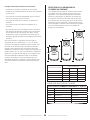
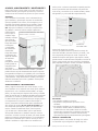
PROPANE TANK SIZE SELECTION
Below are a few quick points of reference for when you
need to select propane cylinders for your applications.
There are two major points to consider. What is the
temperature outside? & What are the BTU requirements
of the heater I will be using. While 20lb, 40lb and 100lb
tanks are the most common tank sizes, there are various
other options available. Contact you propane supplier for
details.
LBS OF LP IN THE CYLINDER
MAXIMUM CONTINUOUS BTU OUTPUT PER HOUR
@ VARIOUS TEMPERATURES
0°F (-18°C) 20°F(-7°C) 40°F (4°C)
200 (2 x 100's) 226,000 334,000 428,000
100 113,000 167,000 214,000
80 (2 x 40's) 94,000 137,000 180,000
40 55,000 79,000 105,000
20 36,000 51,000 69,000
PROPANE TANK SELECTION @ 20°F (-7°C)
HIGH SETTING LOW SETTING
HS115TC 110,833 BTU/HR 80,612 BTU/HR
2 X 40LB TANKS 1 X 40LB TANK
HS190TC 190,200 BTU/HR 127,100 BTU/HR
2 X 100LB TANKS 2 X 40LB TANKS
HS250TC 248,625 BTU/HR 181,119 BTU/HR
2 X 100LB TANKS 2 X 100LB TANKS
EXAMPLE TANK SELECTION
20LBS 40LBS 100LBS
18”
29”
48”
12.5”
12.5”
14.5”
• The flame is contained within the heater.
• The flame is essentially blue with perhaps some yel-
low tipping.
• There is no strong disagreeable odor, eye burning or
other physical discomfort.
• There is no smoke or soot internal or external to the
heater.
• There are no unplanned or unexplained shut downs
of the heater.
• The parts lists and wiring diagram show the heater
as it was constructed. Do not use a heater which is
different from that shown. In this regard, use only
the hose, regulator and cylinder connection fitting
(called a POL fitting) supplied with the heater.
For this heater, the regulator must be set as shown in
„SPECIFICATIONS‰. If there is any uncertainty about the
regulator setting, have it checked. A heater which is not
working right must be repaired, but only by a trained,
experienced service person. The heater is equipped with
a 1 year Limited Warranty, for full warranty information
please read page 20. Please include a brief statement
indicating date, place of purchase, the nature of the
problem and proof of purchase for warranty inquiries.
Out-of-warrranty products can be repaired with a charge
for parts and labor. Contact customer service for a list of
certified repair centers near you.

Operating Instructions and OwnerÊs Manual
11
Forced-Air Dual-Fuel NOMAD Construction Heater
Symptom Troubleshooting
Blower does not come on 1. Make sure the switch is either in the on or fan only posi-
tion
2. Verify the extension cord being used is not too long
3. Check power source is 110v
4. Verify the setting on the thermostat is higher than the
temperature in the space to be heated
Blower runs but the burner does not ignite 1. Make sure the switch is in the on position not in the fan
only position
2. Verify that the fuel connected to the unit is turned on and
flowing. It may take a few cycles to get all the air out of
the lines.
3. Make sure the rate and fuel switch are in the desired posi-
tion for the fuel you are using and the setting (high or
low) that you desire.
Unit producing little heat or no heat. 1. Make sure the switch is in the on position not the fan only
position
2. Make sure the rate and fuel switch are in the desired posi-
tion for the fuel you are using and the setting (high or
low) that you desire.
3. Verify that the fuel pressure being supplied to the heater is
adequate. Refer to the specification table in this manual for
required pressures.
4. Make sure the factory supplied hose and regulator are be-
ing used.
Heater will not shut down 1. Verify the switch is in the off position not on or fan only.
2. Check current setting on the thermostat. Is it set to a tem-
perature higher than the space being heated?
3. Heater will only cycle on and off when optional thermostat
is installed.
Unit will not turn on with thermostat installed 1. Verify that the thermostat is installed correctly. Heater will
only cycle on and off when the optional thermostat is
installed.
2. Verify the setting on the thermostat is higher than the
temperature in the space to be heated
3. Check that the power switch is in the "on" position. The
thermostat will only cycle on and off if the power switch is
in the on position
Unit will not turn off with thermostat installed. 1. Verify the setting of the thermostat is lower than the tem-
perature in the space being heated.
2. Verify that the thermostat is installed correctly, the unit
may just be on the on position.
3. Heater may be undersized or for the space being heated.
Red HLS fault light is on 1. Verify that the path of heat is not obstructed.
2. Check for blockage in the duct and at the end diffuser
3. Check the fuel and rate selections are accurate. If the
wrong fuel is selected the unit will over heat.
FOR FURTHER ASSISTANCE
If after you have reviewed the trouble shooting in this
manual and you still require assistance please use any of
the following methods to contact our technical service
department. We will do our absolute best to resolve any
issues or problems that arise. Most problems can be solved in
just a few minutes.
HOURS ARE: Monday- Friday 8:00am until 5:00pm
CALL: 866-447-2194
FAX: 800-321-0552
VISIT: HEATSTARBYENERCO.COM
INQUIRIES IN CANADA ONLY
PLEASE CALL: 877-477-3353
VISIT IPSPOWER.COM

12
Forced-Air Dual-Fuel NOMAD Construction Heater Operating Instructions and OwnerÊs Manual
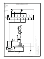
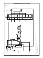
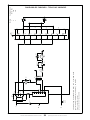
SW1
L
1
2
2A
1B
1A
2B
ign
n/c
n/c
6
5
4
3
2
1
G
VP
N
L
N
led 2
chassis
ground
G
T1
24vac
sail
switch
SW4
hls
led 4
led 5
Gas
Valve
GV1
M
M1
led 1
SW2
3
2
1
1
5
9
3
1
13
15
11
7
2
14
16
12
8
4
10
2
6
SV1
S
SV2
S
Position
1
2
3
Valve(s) Open
SV1 & SV2
SV2
SV1
Chassis wiring is stranded 18 AWG / 105 C / @ 600 Volts
Igniter wiring is16 AWG / 25KVDC / 10 KVAC
(replace with same ratings)
(all quick connects fully insulated)
SW3
WIRING DIAGRAM-ALL UNITS

Operating Instructions and OwnerÊs Manual
13
Forced-Air Dual-Fuel NOMAD Construction Heater
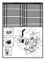
1
23
511
4
9
10
8
6
11
7
12
13
14
15
16
17
19
18
20
22
21
23
24
25
26
27
29
28
41
42
39
40
30
31
32
34
35
33
38
36
37
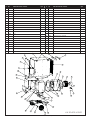
# P/N PART DESCRIPTION QTY
1 60801 HEATER FOOT 2
2 60800 HEATER BASE 1
3 60802 SOLENOID SUPPORT 1
4 60818 COMBUSTION CHAMBER -RIGHT 1
5 60820 COMBUSTION CHAMBER -BACK 1
6 60817 COMBUSTION CHAMBER -LEFT 1
7 60819 COMBUSTION CHAMBER -TOP 1
8 60822 COMBUSTION CHAMBER -UPPER FLANGE 1
9 60821 COMBUSTION CHAMBER -LOWER FLANGE 1
10 60823 LOWER BURNER COVER 1
11 60824 COMBUSTION CHAMBER -HEAT SHIELD 2
12 60813 INSIDE BLOWER PANEL 1
13 60815 BLOWER TUBE 1
14 60816 115 BLOWER WHEEL 1
15 60812 OUTSIDE BLOWER PANEL 1
16 60814 MOTOR MOUNTING PLATE 1
17 60843 115 MOTOR - 1/3HP 1
18 60830 SAIL SWITCH 1
19 60938 SAIL SWITCH BRACKET 1
20 60958 HIGH LIMIT SWITCH 1
21 60833 HEATER COVER 1
# P/N PART DESCRIPTION QTY
22 60835 MOTOR DOOR 1
23 60834 CONTROLS DOOR 1
24 60837 DOOR HINGE 1
25 60839 D-RING LATCH/LOCK 1
26 60847 24V RED LED LAMP - FAULT INDICATOR 1
27 60846 24V GREEN LED LAMP - GAS VALVE ON INDICATOR 1
28 60845 120V LED LAMP - GREEN 2
29 60841 MAIN POWER ROCKER SWITCH 1
30 60883 SELECTOR SWITCH BRACKET 1
31 60842 SELECTOR SWITCH 1
32 27808 FLAME CONTROL BOARD 1
33 60810 115 BURNER 1
34 60827 115 IGNITER BURNER PLATE-FRONT 1
35 60139 IGNITER/FLAME SENSE ASSY. 1
36 60831 115 BURNER CLAMP 1
37 60832 115 BURNER CLAMP BASE 1
38 60826 115 IGNITER BURNER PLATE-BACK 1
39 00600 GAS TRAIN ASSY. 1
40 60129 GAS VALVE 1
41 60848 SOLENOID VALVE 2
42 60809 ORIFICE HOLDER 1
EXPLODED VIEW HS115TC

14
Forced-Air Dual-Fuel NOMAD Construction Heater Operating Instructions and OwnerÊs Manual
NOTES:

Operating Instructions and OwnerÊs Manual
15
Forced-Air Dual-Fuel NOMAD Construction Heater
17
29
16
38
36
35
32
34
33
31
11
10
28
27
13
14
12
19
22
24
23
25
26
18
30
21 20
2
67
8
19
3
45
15
37
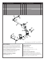
# P/N PART DESCRIPTION QTY
1 60973 190 COVER 1
2 60904 ELECTRICAL DOOR 1
3 60905 MOTOR DOOR 1
4 60906 FIXED PIECE HANDLE MOUNT 1
5 60908 HANDLE 1
6 60916 DOOR HANDLE 1
7 60913 DOOR HANDLE SPACER 1
8 60917 DOOR LATCH 1
9 60915 HOIST RINGS 4
10 60884 BASE 1
11 60901 BASE FOOT 1
12 60802 SOLENOID SUPPORT 1
13 40940 WHEEL 2
14 60902 AXEL 1
15 28787 WHEEL HARDWARE KIT 1
16 60851 SAIL SWITCH 1
17 60938 SAIL SWITCH BRACKET 1
18 60922 COMBUSTION CHAMBER-TOP 1
19 60891 COMBUSTION CHAMBER-LEFT 1
20 60890 COMBUSTION CHAMBER-RIGHT 1
21 60923 COMBUSTION CHAMBER-RIGHT HEAT SHIELD 1
# P/N PART DESCRIPTION QTY
22 90924 COMBUSTION CHAMBER-LEFT HEAT SHIELD 1
23 60892 COMBUSTION CHAMBER-TOP FLANGE 1
24 60893 COMBUSTION CHAMBER-BOTTOM FLANGE 1
25 60925 BURNER STAND-OFF 1
26 60885 COMBUSTION CHAMBER-LOWER HEAT SHIELD 1
27 60974 BLOWER SHELF 1
28 60975 BLOWER SHELF SUPPORT 1
29 60962 HIGH LIMIT SWITCH 1
30 60894 COMBUSTION CHAMBER SUPPORT 2
31 60977 HOUSING RIGHT SIDE 1
32 60978 BLOWER TUBE 1
33 60981 HOUSING DEFLECTOR ATTACHMENT 1
34 60980 HOUSING INLET ADAPTER 1
35 60976 HOUSING LEFT SIDE 1
36 60979 MOTOR MOUNT 1
37 60998 190 BLOWER WHEEL 1
38 60971 1/2HP MOTOR 190 1
EXPLODED VIEW HS190TC

16
Forced-Air Dual-Fuel NOMAD Construction Heater Operating Instructions and OwnerÊs Manual
NOTES:

Operating Instructions and OwnerÊs Manual
17
Forced-Air Dual-Fuel NOMAD Construction Heater
194
5
3
7
6
2
8
21
20
18
26
23
24
19
2227
28
12 14
13 11
10
31
34
32
35
16
17
29
37
36
33
30
15
38
EXPLODED VIEW HS250TC
# P/N PART DESCRIPTION QTY
1 60903 250 COVER 1
2 60904 ELECTRICAL DOOR 1
3 60905 MOTOR DOOR 1
4 60906 FIXED PIECE HANDLE MOUNT 1
5 60908 HANDLE 1
6 60916 DOOR HANDLE 1
7 60913 DOOR HANDLE SPACER 1
8 60917 DOOR LATCH 1
9 60915 HOIST RINGS 4
10 60900 BASE 1
11 60901 BASE FOOT 1
12 60802 SOLENOID SUPPORT 1
13 40940 WHEEL 2
14 60902 AXEL 1
15 28787 WHEEL HARDWARE KIT 1
16 60851 SAIL SWITCH 1
17 60938 SAIL SWITCH BRACKET 1
18 60922 COMBUSTION CHAMBER-TOP 1
19 60919 COMBUSTION CHAMBER-LEFT 1
20 60918 COMBUSTION CHAMBER-RIGHT 1
21 60923 COMBUSTION CHAMBER-RIGHT HEAT SHIELD 1
# P/N PART DESCRIPTION QTY
22 60924 COMBUSTION CHAMBER-LEFT HEAT SHIELD 1
23 60920 COMBUSTION CHAMBER-TOP FLANGE 1
24 60921 COMBUSTION CHAMBER-BOTTOM FLANGE 1
25 60925 BURNER STAND-OFF 1
26 60885 COMBUSTION CHAMBER-LOWER HEAT SHIELD 1
27 60930 BLOWER SHELF 1
28 60931 BLOWER SHELF SUPPORT 1
29 HIGH LIMIT SWITCH 1
30 60894 COMBUSTION CHAMBER SUPPORT 2
31 60933 HOUSING RIGHT SIDE 1
32 60934 BLOWER TUBE 1
33 60937 HOUSING DEFLECTOR ATTACHMENT 1
34 60936 HOUSING INLET ADAPTER 1
35 60932 HOUSING LEFT SIDE 1
36 60935 MOTOR MOUNT 1
37 60940 250 BLOWER WHEEL 1
38 60960 3/4 HP MOTOR 190 1

18
Forced-Air Dual-Fuel NOMAD Construction Heater Operating Instructions and OwnerÊs Manual
NOTES:

Operating Instructions and OwnerÊs Manual
19
Forced-Air Dual-Fuel NOMAD Construction Heater
# P/N PART DESCRIPTION QTY
1 60129 HONEYWELL GAS VALVE 1
2 60848 SOLENOID VALVE 2
3 70597 3/8" FPT X 3/8" MPT - STREET ELBOW 1
4 60804 3/8" PIPE CLOSE NIPPLE 1
5 60948 ORIFICE HOLDER 1
6 60949 GAS VALVE BRACKET 1
7 60805 3/8" X 3 PIPE NIPPLE 1
8 60955 1/2" FPT X 3/8" MPT - STREET ELBOW 1
9 60954 1/2" PIPE CLOSE NIPPLE 1
10 60956 1/2" X 10" PIPE NIPPLE 1
# P/N PART DESCRIPTION QTY
11 02724 1/2" X 4" PIPE NIPPLE 1
12 60957 1/2" X 1/2" ELBOW 1
13 02744 1/2" MALE FLARE 1
14-A 60881 250 BYPASS ORIFICE 1 1
15-A 60882 250 BYPASS ORIFICE 2 1
16-A 60880 250 MAIN ORIFICE 1
14-B 60878 190 BYPASS ORIFICE 1 1
15-B 60879 190 BYPASS ORIFICE 2 1
16-B 60887 190 BYPASS ORIFICE 2 1
16
57
3
14
2
415 2
8
9
6
1
10
12
11
13
WARNING:
USE ONLY MANUFACTURERÊS REPLACEMENT PARTS. USE OF ANY
OTHER PARTS COULD CAUSE INJURY OR DEATH. REPLACEMENT
PARTS ARE ONLY AVAILABLE DIRECT FROM THE FACTORY AND
MUST BE INSTALLED BY A QUALIFIED SERVICE AGENCY.
FOR SERVICE OR PARTS INQUIRIES
PLEASE CALL: 866-447-2194 OR 216-916-3000
VISIT: WWWHEATSTARBYENERCO.COM
INQUIRIES IN CANADA ONLY
PLEASE CALL: 877-477-3353
VISIT IPSPOWER.COM
COROPORATE ADDRESS
HEATSTAR BY ENERCO
4560 WEST 160TH STREET
CLEVELAND, OHIO 44135
OUR OFFICE HOURS ARE 8:00 AM -5:00 PM EST MONDAY-FRIDAY
WHEN CONTACTING US:
PLEASE HAVE YOUR SERIAL NUMBER AND MODEL NUMBER HANDY.
THESE CAN BOTH BE LOCATED ON THE RATING LABEL LOCATED ON
THE INSIDE OF THE ACCESS PANEL.
RETAIN THIS MANUAL FOR FUTURE REFERENCE.
Gas Train for HS190TC & HS250TC

WARNING:
USE ONLY MANUFACTURERÊS REPLACEMENT PARTS. USE OF ANY OTHER PARTS
COULD CAUSE INJURY OR DEATH. REPLACEMENT PARTS ARE ONLY AVAILABLE DIRECT
FROM THE FACTORY AND MUST BE INSTALLED BY A QUALIFIED SERVICE AGENCY.
PARTS ORDERING INFORMATION:
PURCHASING: Accessories may be purchased at any HEAT STAR local dealer or direct
from the factory
FOR INFORMATION REGARDING SERVICE
Please call Toll-Free 866-447-2194 • HEATSTARBYENERCO.COM
Our office hours are 8:00 AM – 5:00 PM, EST, Monday through Friday.
Please include the model number, date of purchase, and description of problem in all
communication.
LIMITED WARRANTY
The company warrants this product to be free from imperfections in material or
workmanship, under normal and proper use in accordance with instructions of
The Company, for a period of one year from the date of delivery to the buyer. The
Company, at its option, will repair or replace products returned by the buyer to the
factory, transportation prepaid within said one year period and found by the Company
to have imperfections in material or workmanship.
If a part is damaged or missing, call our Technical Support Department at 866-447-2194.
Address any Warranty Claims to the Service Department, HEAT STAR Group, Inc.,
4560 W. 160th St., Cleveland, Ohio 44135. Include your name, address and telephone
number and include details concerning the claim. Also, supply us with the purchase
date and the name and address of the dealer from whom you purchased our product.
The foregoing is the full extent of the responsibility of the Company. There are no
other warranties, express or implied. Specifically there is no warranty of fitness for a
particular purpose and there is no warranty of merchantability. In no event shall the
Company be liable for delay caused by imperfections, for consequential damages, or
for any charges of the expense of any nature incurred without its written consent. The
cost of repair or replacement shall be the exclusive remedy for any breach of warranty.
There is no warranty against infringement of the like and no implied warranty arising
from course of dealing or usage of trade. This warranty will not apply to any product
which has been repaired or altered outside of the factory in any respect which in our
judgment affects its condition or operation.
Some states do not allow the exclusion or limitation of incidental or consequential
damages, so the above limitation or exclusion may not apply to you. This Warranty gives
you specific legal rights, and you may have other rights which vary from state to state.
HEAT STAR Group, Inc. reserves the right to make changes at any time, without notice or
obligation, in colors, specifications, accessories, materials and models.
HEAT STAR, INC., 4560 W. 160TH ST., CLEVELAND, OHIO 44135 • 866-447-2194
ANSI Z83.7b-2009/CSA 2.14b-2009
OPERATING INSTRUCTIONS
AND OWNER’S MANUAL
READ INSTRUCTIONS CAREFULLY: Read and follow all instructions. Place instructions in a safe
place for future reference. Do not allow anyone who has not read these instructions to assemble,
light, adjust or operate the heater.
Model #
PRODUCT REGISTRATION: Thank you for your purchase.
Please log in to HEATSTARBYENERCO.COM to register your product.
HS115TC
HS190TC
HS250TC
La page est en cours de chargement...
La page est en cours de chargement...
La page est en cours de chargement...
La page est en cours de chargement...
La page est en cours de chargement...
La page est en cours de chargement...
La page est en cours de chargement...
La page est en cours de chargement...
La page est en cours de chargement...
La page est en cours de chargement...
La page est en cours de chargement...
La page est en cours de chargement...
La page est en cours de chargement...
La page est en cours de chargement...
La page est en cours de chargement...
La page est en cours de chargement...
La page est en cours de chargement...
La page est en cours de chargement...
La page est en cours de chargement...
La page est en cours de chargement...
La page est en cours de chargement...
La page est en cours de chargement...
La page est en cours de chargement...
La page est en cours de chargement...
La page est en cours de chargement...
La page est en cours de chargement...
La page est en cours de chargement...
La page est en cours de chargement...
La page est en cours de chargement...
La page est en cours de chargement...
La page est en cours de chargement...
La page est en cours de chargement...
La page est en cours de chargement...
La page est en cours de chargement...
La page est en cours de chargement...
La page est en cours de chargement...
La page est en cours de chargement...
La page est en cours de chargement...
La page est en cours de chargement...
La page est en cours de chargement...
-
 1
1
-
 2
2
-
 3
3
-
 4
4
-
 5
5
-
 6
6
-
 7
7
-
 8
8
-
 9
9
-
 10
10
-
 11
11
-
 12
12
-
 13
13
-
 14
14
-
 15
15
-
 16
16
-
 17
17
-
 18
18
-
 19
19
-
 20
20
-
 21
21
-
 22
22
-
 23
23
-
 24
24
-
 25
25
-
 26
26
-
 27
27
-
 28
28
-
 29
29
-
 30
30
-
 31
31
-
 32
32
-
 33
33
-
 34
34
-
 35
35
-
 36
36
-
 37
37
-
 38
38
-
 39
39
-
 40
40
-
 41
41
-
 42
42
-
 43
43
-
 44
44
-
 45
45
-
 46
46
-
 47
47
-
 48
48
-
 49
49
-
 50
50
-
 51
51
-
 52
52
-
 53
53
-
 54
54
-
 55
55
-
 56
56
-
 57
57
-
 58
58
-
 59
59
-
 60
60


HeatStar HS115TC Le manuel du propriétaire
- Taper
- Le manuel du propriétaire
dans d''autres langues
- English: HeatStar HS115TC Owner's manual
- español: HeatStar HS115TC El manual del propietario
Documents connexes
Autres documents
-
Mr. Heater MH400FAVT Operating Instructions And Owner's Manual
-
-
DeWalt DXH125FAVHC Mode d'emploi
-
-
-
Power Fist 8677486 Le manuel du propriétaire
-
-
-
Honeywell SV2 Series Valve Programming Tool HMITOOL-000 Mode d'emploi
-
WilTec 60317 Manuel utilisateur