BLACK+DECKER BDSTGA9701 Manuel utilisateur
- Taper
- Manuel utilisateur

Tumbling Composter Assembly Instructions
Composteur à Tambour Rotative Instructions D’assemblage
Compostador Giratorio Instrucciones de Ensamble
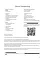
Scan the QR code to learn more and to view a product assembly video
Balayez le code QR pour en savoir plus et pour regarder une vidéo d’assemblage du produit
Escanee el código QR para obtener más información y ver un vídeo de ensamble del producto

2
Table of Contents | Table des Matières | Tabla de Contenido
INSTRUCTION MANUAL ......................................................................................................................... 3
WARNING ...................................................................................................................................................... 5
Assembly Instructions ................................................................................................................................... 6
Materials ................................................................................................................................................... 6
Section 1: Assemble the Composter Barrel .............................................................................................. 8
Section 2: Assemble the Base ................................................................................................................. 15
Section 3: Install the Composter Barrel on the Base .............................................................................. 20
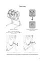
Features ...................................................................................................................................................... 23
About Composting ...................................................................................................................................... 24
MANUAL DE INSTRUCCIONES ............................................................................................................ 25
AVERTISSEMENT ......................................................................................................................................... 27
Instructions d’assemblage .......................................................................................................................... 28
Matériel ................................................................................................................................................... 28
Section 1: Assembler le Tambour du Composteur ................................................................................. 30
Section 2: Assembler la Base .................................................................................................................. 37
Section 3: Installer le Tambour du Composteur sur la Base ................................................................... 42
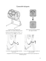
Caractéristiques .......................................................................................................................................... 45
À Propos du Compostage ............................................................................................................................ 46
MANUAL DE INSTRUCCIONES ............................................................................................................ 47
ADVERTENCIA ............................................................................................................................................. 49
Instrucciones de Ensamble ......................................................................................................................... 50
Materiales ............................................................................................................................................... 50
Sección 1: Ensamble de Barril de Compostador ..................................................................................... 52
Sección 2: Ensamble la Base.................................................................................................................. 59
Sección 3: Instale el Barril de Compostador en la Base .......................................................................... 64
Características ............................................................................................................................................. 67
Acerca del Compostaje ............................................................................................................................... 68

3
INSTRUCTION MANUAL
Please read before returning this product for any reason.
WARNING: Read all safety warnings and all instructions.
Failure to follow the warnings and instructions may result
in electric shock, fire and/or serious injury.
WARNING: To reduce the risk of injury, read the
instruction manual.
Intended Use
Your BLACK+DECKER, BDSTGA9701 has been designed for
household, consumer use only. This barrel composter is
designed to mix typical green and brown compostables.
DO NOT let children come into contact with the product.
Supervision is required when inexperienced operators use
this product.
Definitions: Safety Alert Symbols and Words
This instruction manual uses the following safety alert symbols
and words to alert you to hazardous situations and your risk of
personal injury or property damage.
DANGER: Indicates an imminently hazardous situation
which, if not avoided, will result in death or serious injury.
WARNING: Indicates a potentially hazardous situation
which, if not avoided, could result in death or
serious injury.
CAUTION: Indicates a potentially hazardous situation
which, if not avoided, may result in minor or
moderate injury.
(Used without word) Indicates a safety related message.
NOTICE: Indicates a practice not related to personal injury
which, if not avoided, may result in property damage.
Composting Safety Warnings
WARNING: Failure to follow these warnings may result in
serious personal injury or property damage.
CAUTION: Rotating gears can pinch fingers.
CAUTION: Opening or closing the doors can pinch fingers.
• Use care when using sharp objects to remove compost to
avoid damaging the composter barrel.
• Do not rotate composter barrel with doors open.
• Stand clear of handle as it may spin fast.
• Assemble on a smooth, level surface.
• Wear appropriate gloves and eye protection when using and
assembling composter.
• Keep hands and loose clothing away from the composter
barrel when rotating.
• Keep children away from the composter.
• Remove the composter barrel from the frame before moving
or relocating the unit.
• Remove composter barrel doors when emptying compost.
• Be aware that plastic panels can be damaged by over
tightening the connections.
• Do not overload the composter barrel. The maximum
composter barrel load is 60 lbs.
• Do not rotate the composter barrel when compost material
is frozen.
• Do not climb on, in, or around the composter.
• Do not use or store hot objects near the plastic composter.
Additional Safety Information
WARNING: Never modify the product or any part of it.
Damage or personal injury could result.
WARNING: ALWAYS use safety glasses. Everyday
eyeglasses are NOT safety glasses. Also use face or dust
mask if operation is dusty. ALWAYS WEAR CERTIFIED
SAFETY EQUIPMENT:
• ANSI Z87.1 eye protection (CAN/CSA Z94.3),
• ANSI S12.6 (S3.19) hearing protection,
• NIOSH/OSHA/MSHA respiratory protection.
WARNING: Some dust contains chemicals known to State
of California to cause cancer, birth defects or other
reproductive harm. Some examples of these chemicals are:
• compounds in fertilizers,
• compounds in insecticides, herbicides and pesticides,
• arsenic and chromium from chemically treated lumber.
To reduce your exposure to these chemicals, wear
approved safety equipment such as dust masks that are
specially designed to filter out microscopic particles.
WARNING: Use of this product can generate and/or
disperse dust, which may cause serious and permanent
respiratory or other injury. Always use NIOSH/OSHA
approved respiratory protection appropriate for the dust
exposure. Direct particles away from face and body.
• Air vents often cover moving parts and should be avoided.
Loose clothes, jewelry or long hair can be caught in
moving parts.

4
MAINTENANCE
WARNING: To reduce the risk of serious personal injury,
wear gloves and protective eye wear before assembling,
making any adjustments or removing/installing
attachments or accessories. Failure to follow these
warnings may result in serious personal injury or property
damage.
Your BLACK+DECKER product has been designed to operate
over a long period of time with a minimum of maintenance.
Continuous satisfactory operation depends upon proper care
and regular cleaning.
Cleaning
WARNING: Blow dirt and dust out of all air vents with
clean, dry air at least once a week. To minimize the risk of
eye injury, always wear ANSI Z87.1 approved eye
protection when performing this procedure.
WARNING: Never use solvents or other harsh chemicals
for cleaning the non
‑
metallic parts of the tool. These
chemicals may weaken the plastic materials used in these
parts. Use a cloth dampened only with water and mild
soap. Never let any liquid get inside the tool; never
immerse any part of the tool into a liquid.
Accessories
WARNING: Since accessories, other than those offered by
BLACK+DECKER, have not been tested with this product,
use of such accessories with this product could be
hazardous. To reduce the risk of injury, only
BLACK+DECKER recommended accessories should be
used with this product.
Recommended accessories for use with your product are
available at extra cost from your local dealer or authorized
service center. If you need assistance in locating any accessory,
please contact BLACK+DECKER call 1‑800‑544‑6986.
Repairs
WARNING: To assure product SAFETY and RELIABILITY,
repairs, maintenance and adjustment (including brush
inspection and replacement, when applicable) should be
performed by a BLACK+DECKER factory service center or
a BLACK+DECKER authorized service center. Always use
identical replacement parts.
Register Online
Thank you for your purchase. Register your product now for:
WARRANTY SERVICE: Registering your product will help you
obtain more efficient warranty service in case there is a
problem with your product.
CONFIRMATION OF OWNERSHIP: In case of an insurance
loss, such as fire, flood or theft, your registration of ownership
will serve as your proof of purchase.
FOR YOUR SAFETY: Registering your product will allow us to
contact you in the unlikely event a safety notification is
required under the Federal Consumer Safety Act.
Register online at www.BlackandDecker.com/NewOwner
TWO‑YEAR LIMITED WARRANTY
Black & Decker (U.S.) Inc. warranties this product to be free from
defects in material or workmanship for a period of two (
2
) years
following the date of purchase, provided that the product is
used in a home environment. This limited warranty does not
cover failures due to abuse, accidental damage or when repairs
have been made or attempted by anyone other than
BLACK+DECKER and its Authorized Service Centers. A defective
product meeting the warranty conditions set forth herein will be
replaced or repaired at no charge in either of two ways:
The first, which will result in exchanges only, is to return the
product to the retailer from whom it was purchased (provided
that the store is a participating retailer). Returns should be made
within the time period of the retailer’s policy for exchanges.
Proof of purchase may be required. Please check with the
retailer for its specific return policy regarding time limits for
returns or exchanges. The second option is to take or send the
product (prepaid) to a BLACK+DECKER owned or authorized
Service Center for repair or replacement at BLACK+DECKER’s
option. Proof of purchase may be required. BLACK+DECKER
owned and authorized service centers are listed online at
ww.blackanddecker.com. This warranty does not apply to
accessories. This warranty gives you specific legal rights and you
may have other rights which vary from state to state or province
to province. Should you have any questions, contact the
manager of your nearest BLACK+DECKER Service Center. This
product is not intended for commercial use, and accordingly,
such commercial use of this product will void this warranty. All
other guarantees, express or implied, are hereby disclaimed.
LATIN AMERICA: This warranty does not apply to products sold
in Latin America. For products sold in Latin America, check
country specific warranty information contained in the
packaging, call the local company or see the website for
such information.
Imported by Black & Decker (U.S.) Inc.,
701 E. Joppa Rd.
Towson, MD 21286

5
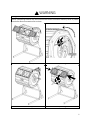
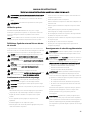
WARNING
Safety glasses required for assembly
NOTICE: Composting contents may stain some surfaces such as concrete or masonry. Cover or protect
areas before placing composting unit on them.
Do not rotate barrel with doors open
CAUTION: Gears can pinch fingers
Stand clear of handle as it may spin fast
CAUTION: Doors can pinch fingers

6
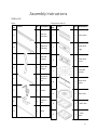
Assembly Instructions
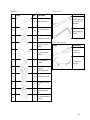
Materials
Base
Part
No.
Picture
Qty
Description
A
1
Left arm
assembly
B
1
Right arm
assembly
C
1
Left side
support
D
1
Right side
support
E
2
Horizontal
stabilizer
bar
F
1
Handle
G
1
Rotation
lock
H
1
Shaft
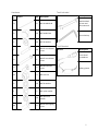
Composter barrel
Part
No.
Picture
Qty
Description
I
5
Plain panel
J
1
Panel with
logo
K
1
Panel with
vents
L
1
Chamber
divider
M
1
Door base
panel
N
2
Side cover
O
1
"Add" door
P
1
"Time"
door

7
Hardware
Part
No.
Picture
Qty
Description
Q
8
M5 threaded rod
R
16
M5 hooded nut
S
16
M5 flat washer
T
10
M6x35 round head
screw
U
1
M6x55 round head
screw
V
2
M6x18 flat head
screw
W
3
M6 Lock nut
X
10
M6 flat washer
Y
2
M6 nylon washer
Z
10
M6 open lock
washer
AA
2
M4x15 Self tapping
screw
Tools Included
Picture
Description
Double sided
10 mm and
8 mm wrench
4 mm hex key
Tools Needed
Picture
Description
Cross head
screwdriver
Safety glasses

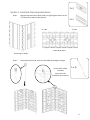
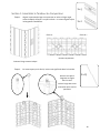
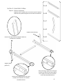
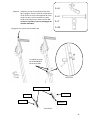
8
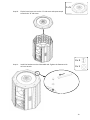
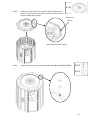
Ensure tab is nested
in channel
Insert rod in this
orientation for all panels
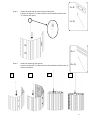
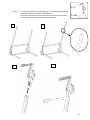
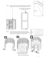
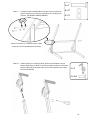
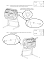
Section 1: Assemble the Composter Barrel
Step 1. Align the logo panel and a plain panel at a slight angle as shown so the
“A” sides line up and the tabs interlock.
Step 2. Starting from the A side, insert one threaded rod through the hinge.
“A” side
“B” side
Underside of panel
Orient logo as shown
1 x
J
1 x
I
1 x
Q

9
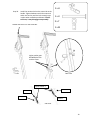
Step 3. Install the panel with air vents onto the plain panel.
Continue to align the “A” sides and insert the threaded rods from the
“A” side for each panel.
Step 4. Install the remaining plain panels.
Continue to align the “A” sides and insert the threaded rods from the “A”
side for each panel.
1.
2.
3.
4.
1 x
K
1 x
Q
4 x
I
4 x
Q

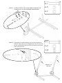
10
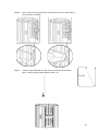
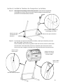
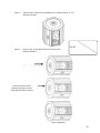
Note location of the “A” and “B” side
labels
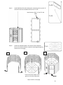
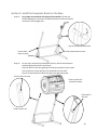
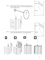
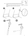
Step 5. Install ONE side of the door base panel, continuing to line up the “A”
sides and insert the threaded rod from the “A” side.
Step 6. Install the chamber divider in the center of the composter.
Ensure the chamber divider is seated in the designated groove,
shown on the next page.
Ensure the center divider sits in
groove on the door base panel
1 x
L
Step 6 cont’d on next page
1 x
M
1 x
Q
2.
1.
3.

11
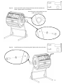
Step 6. Continued- Ensure the chamber divider is seated in the designated groove.
Step 7. Install the threaded rod in the remaining side of the door base panel.
Insert the threaded rods from the “A” side.
1 x
Q

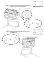
12
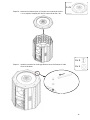
Step 8. Install one side cover to the "A" side of the barrel.
Fit the panels in the groove in the side cover and align the holes
with the threaded rods in the panels.
Step 9. Install the hardware on the 8 threaded rods. DO NOT FULLY TIGHTEN.
Underside of side cover
1 x
N
8 x
R
8 x
S
Groove for
panels

13
Step 10. Flip the barrel over to sit on the “A” side cover and repeat step 8
to attach the “B” side cover.
Step 11. Install the hardware on the 8 threaded rods. Tighten the fasteners with
an 8 mm wrench.
1 x
N
8 x
R
8 x
S

14
Step 12. Flip barrel over and tighten the fasteners on the “A” side cover with an
8 mm wrench.
Step 13. Insert the shaft through the hole in the center of the
side covers.
Completed barrel
Reach inside the openings to
guide shaft through the
chamber divider
1 x
H

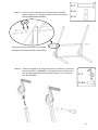
15
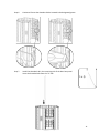
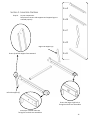
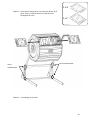
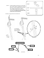
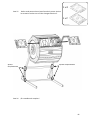
Section 2: Assemble the Base
Step 14. Lay out components.
See picture to ensure side supports and support legs are
oriented properly.
Left side support (C)
Right side support (D)
Ensure lip of side support faces outward
Ensure the large, single hole is
facing IN on both arm assemblies
Ensure the 3 smaller holes are
facing OUT on both arm assemblies
1 x
A
1 x
B
1 x
C
1 x
D
1 x
E

16
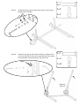
Step 15. Install the fasteners in the order shown using a 4 mm hex key.
DO NOT FULLY TIGHTEN.
Step 16. Rotate the top legs up and install the fasteners. Tighten with a
4 mm hex key and 10 mm wrench simultaneously, then tighten
the screw above it (see picture) with the same tools.
Repeat on
right side
2 x
T
2 x
X
2 x
W
4 x
T
4 x
Z
4 x
X
Tighten
X
Z

17
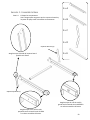
Step 17. Place a horizontal stabilizer bar between the top support legs and
install the fasteners in the order shown. DO NOT FULLY TIGHTEN.
Step 18. Install the handle on the main leg. Tighten fasteners with a cross head
screwdriver. NOTE: Handle can be installed on left support arm for left-
handed operation. See Step 19 for details.
Align the holes in the side support, main leg, and
horizontal stabilizer bar
4 x
T
4 x
Z
4 x
X
1 x
F
2 x
AA
Z
X

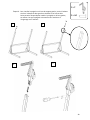
18
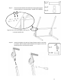
Step 19. To install the handle on the left support arm, remove the end cap on the
top of the left arm and install it on the right arm.
Then follow Step 18 to install the handle on the left arm, ensuring that
the handle faces outwards and the gear faces inwards.
1.
2.
1 x
F
2 x
AA
4.
5.

19
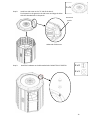
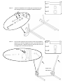
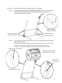
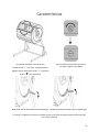
Step 20. Install the rotation lock on the same side as the
handle. Tighten hardware with 10 mm wrench
and 4 mm hex key until the lock securely stays
in place when rotated up and down. If lock is
too loose, it may disengage unexpectedly.
1 x
H
1 x
U
2 x
Y
1 x
W
Handle and lock are on the same side.
Nylon washer goes
BETWEEN the lock
and the frame
Back view
Bolt U
Lock H
Nylon washer Y
Lock H
Nut W
Side view

20
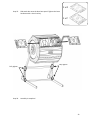
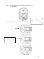
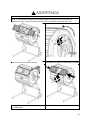
Section 3: Install the Composter Barrel on the Base
Step 21. Two people are needed for this stage of the assembly. Flip the lock
handle downwards, and ensure the indicated bolts are loose to allow for
movement of the upright arms.
Step 22. For this step, one person should hold the barrel, and the second person
should help guide the shaft into the base.
Place the barrel in the base, guiding the shaft into the holes on the inside
of the base arms. Gently pull the arms outwards to fit the shaft.
Ensure the handle does not block the side of the door base panel.
Ensure these
bolts are loose
Ensure these bolts are loose
Flip the lock handle downward
Ensure the barrel is
oriented as shown
Place shaft in this hole
Place shaft in
this hole
Inside of main arm
La page est en cours de chargement...
La page est en cours de chargement...
La page est en cours de chargement...
La page est en cours de chargement...
La page est en cours de chargement...
La page est en cours de chargement...
La page est en cours de chargement...
La page est en cours de chargement...
La page est en cours de chargement...
La page est en cours de chargement...
La page est en cours de chargement...
La page est en cours de chargement...
La page est en cours de chargement...
La page est en cours de chargement...
La page est en cours de chargement...
La page est en cours de chargement...
La page est en cours de chargement...
La page est en cours de chargement...
La page est en cours de chargement...
La page est en cours de chargement...
La page est en cours de chargement...
La page est en cours de chargement...
La page est en cours de chargement...
La page est en cours de chargement...
La page est en cours de chargement...
La page est en cours de chargement...
La page est en cours de chargement...
La page est en cours de chargement...
La page est en cours de chargement...
La page est en cours de chargement...
La page est en cours de chargement...
La page est en cours de chargement...
La page est en cours de chargement...
La page est en cours de chargement...
La page est en cours de chargement...
La page est en cours de chargement...
La page est en cours de chargement...
La page est en cours de chargement...
La page est en cours de chargement...
La page est en cours de chargement...
La page est en cours de chargement...
La page est en cours de chargement...
La page est en cours de chargement...
La page est en cours de chargement...
La page est en cours de chargement...
La page est en cours de chargement...
La page est en cours de chargement...
La page est en cours de chargement...
-
 1
1
-
 2
2
-
 3
3
-
 4
4
-
 5
5
-
 6
6
-
 7
7
-
 8
8
-
 9
9
-
 10
10
-
 11
11
-
 12
12
-
 13
13
-
 14
14
-
 15
15
-
 16
16
-
 17
17
-
 18
18
-
 19
19
-
 20
20
-
 21
21
-
 22
22
-
 23
23
-
 24
24
-
 25
25
-
 26
26
-
 27
27
-
 28
28
-
 29
29
-
 30
30
-
 31
31
-
 32
32
-
 33
33
-
 34
34
-
 35
35
-
 36
36
-
 37
37
-
 38
38
-
 39
39
-
 40
40
-
 41
41
-
 42
42
-
 43
43
-
 44
44
-
 45
45
-
 46
46
-
 47
47
-
 48
48
-
 49
49
-
 50
50
-
 51
51
-
 52
52
-
 53
53
-
 54
54
-
 55
55
-
 56
56
-
 57
57
-
 58
58
-
 59
59
-
 60
60
-
 61
61
-
 62
62
-
 63
63
-
 64
64
-
 65
65
-
 66
66
-
 67
67
-
 68
68


BLACK+DECKER BDSTGA9701 Manuel utilisateur
- Taper
- Manuel utilisateur
dans d''autres langues
- English: BLACK+DECKER BDSTGA9701 User manual
- español: BLACK+DECKER BDSTGA9701 Manual de usuario
Autres documents
-
 Miracle-Gro DC2105MG Mode d'emploi
-
Genesis GEN-C42-OR Manuel utilisateur
-
 FCMP RC2000WB Outdoor Half Size Rolling Composter Mode d'emploi
-
 Ecovi 97282610 Mode d'emploi
-
FCMP Outdoor HF-DBC4000 Mode d'emploi
-
 FCMP Outdoor IM4000 Mode d'emploi
-
-
Lifetime 60309 Le manuel du propriétaire
-
-
 Mon Petit Potager 61185490 Mode d'emploi


