
Shading Systems
TS Series with DLM or QIS DC Motor
Installation Instructions
No: D000137 – 03/21 rev. 1
Catalog Numbers • Les Numéros de Catalogue • Los Números de Catálogo: SF-TQ7M, SF-TQ10M
Country of Origin: Made in Canada • Pays d’origine: Fabriqué en Canada • País de origen: Hecho en Canadá
CAUTION – Be sure to follow all appropriate safety guidelines, including the use
of safety glasses and ensure to keep the shade fabric clean by using clean gloves
whenever touching it.
Tools Required/Recommended:
• Cable Management / Cable Tie Downs
• Measuring Tape
• Power Drill with 3/32” Bit & 1/4” Nut Driver
• Flat Head Screwdriver
• #2 Phillips Head Screwdriver
• Level
• Pencil
• Ladder
Package Contents:
• Hardwired Roller Shade
• Motor Side Bracket
• Spring Side Bracket
• End Cap x 2
• Fascia (Optional)
• Mounting Screws
Separately Packaged, as ordered:
• Power & Communication Panel
• Power Brick & Cord
• Wall Switch (Optional)
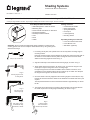
Fig. 1
Snap-In Clip on Teleshade
Fig. 2
Mounting Angle for Face
or Ceiling Mount
Fig. 3
Align Snap-In Clip
to Mounting Angle
Fig. 4
Push Snap-In Clip Up
to Install Shade Using
Screwdriver, if Needed
CLICK
Fig. 5
To Remove Shade
Place a Screwdriver
Between Clips and Twist
1. If mounting into drywall, use a plastic anchor to securely fasten mounting angle to
mounting surface.
Note that mounting angles must be attached to at least 3/4” less than the full width of
the shade so not to interfere with the plastic housings at either end of the shade.
Attach the mounting angles as shown in Fig. 2.
2. Align the inside clip on the shade with the mounting angle, as shown in Fig. 3.
3. Tilt the shade back to level position, as shown in Fig. 4 to allow the tongue on the
inside clip to snap into the groove on the mounting angle.
If tongue and groove do not make an audible click to indicate connection, use a
screwdriver to push up behind fabric roll onto inside of clip on shade. This will push
the tongue into the groove and ensure a solid mount.
4. Once the shade is securely clipped into the mounting angles on each side, the stop
bead to set the lower limit of the shade can be attached to the bead chain with a pair
of pliers.
The stop bead should be set so that the bottom hembar is approximately 1/2” above
the sill.
5. The shade can be taken down by inserting a flat screwdriver into the gap between
the inside clip and the mounting angle and twisting, as shown in Fig 5.

2
Legrand products are designed for use with Legrand hardware and power supplies only. Install in compliance with all local and national
building and electrical codes. Always wear personal protection equipment including safety glasses and gloves. Use a ladder per its
manufacturer’s instructions.
Before installing the shade into the window, verify that window hardware (latches, locks, window cranks, etc.) does NOT obstruct the
travel path of the shade. Damage to the fabric or shade may result from repeated contact with window hardware.
FALLING HAZARD: Shades must be installed to proper support structure.
Locate the shade’s mounting type on the order form (Inside Mount, Outside Mount).
Determine roll type (Standard Roll, Reverse Roll).
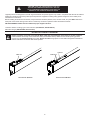
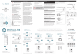
DC MOTOR CABLE PLACEMENT
Failure to properly orient and secure the DC Motor Cable may lead to damage of the shade or window enclosure.
Cable should be routed atop of the shade fabric tube (see illustration below). Make sure the bracket spacing provides
enough room to prevent pinching of the cable. Secure the cable using zip-ties or other cable management hardware so
that the cable does not interfere with shade operation.
CAUTION: READ AND UNDERSTAND EACH SECTION
BEFORE PERFORMING REQUIRED STEPS. FAILURE
TO FOLLOW PROPER PROCEDURE COULD RESULT IN
DAMAGE TO THE SHADE OR PERSONAL INJURY.
Cable Tie
Cable Ties
Antenna
Teleshade with QIS Motor Teleshade with DLM Motor

3
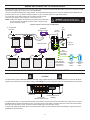
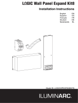
WIRING AND CONNECTING TO A DLM NETWORK
For Teleshades with a DLM motor, the motor whip on the motor connects to a DLM Shade Bus cable, which in turn connects to a DLM
Shade Power Supply, with or without use of the LMSH-SBE4.
There are two different shade power supply models. The LMSH-PS602 provides power for up to two shades and the LMSH-PS-610
provides power for up to 10 shades. Shade Controllers can be connected together for larger shade setups.
The controllers accept 120/277VAC input line voltage and are typically
mounted in the ceiling to a four-square or 4 11/16 junction box.
NOTE: Install power supplies so that switch and shade bus wire bus limits
are not exceeded. The shade bus limit is 1000’ or 500 ft per port
and the DLM limit is 1000’
Line
Voltage
Line/Hot
Black wire
Neutral
White wire
Ground
Green wire
LMSH-SW10x
Shade
Switch
LMSH-SW105
Shade
Switch
LMSH-SBE4
Shade Bus Extender
DLM
Local Network
Low Voltage
LMRJ Cables
Shade Bus Cables
LMSH-PS610
13 “ Pre-terminated
Motor Whip
to additional
Shade Controllers
(Up to 48 DLM devices -
motors, switches,
controllers, etc.)
WARNING: TURN THE POWER OFF AT
THE CIRCUIT BREAKER BEFORE WIRING.
Example of Shade connection with an LMSH-PS610
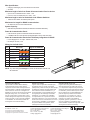
QIS DC MOTOR POWER & COMMUNICATION PANEL SETUP
CAUTION
The QIS DC Motor System does not operate on “standard” Power of Ethernet (PoE) schemes. Do not attempt to connect the DC Motor
System to any PoE device or RJ-45 PoE port. Doing so will damage the system components and/or the external Ethernet or PoE device.
Power Port
Device Port
(Shades and Switches)
Communication Port
(RS485)
Use CAT5e/CAT6 wire to connect DC Motor shades to the Power & Communication Panel. Terminate wires using RJ-45 connectors
(T568B Standard). QIS DC shades will Jog upon connecting power to the shade. The Amber LEDs on the Power & Communication
Panel (RJ-45) ports signify “power” is active. The Green LEDs signify communication activity.
To daisy chain additional DC Motor Power & Communication Panels, use the Communication Ports (RS485) to expand the system
capabilities up to 200 devices.

Limited Lifetime Warranty
Legrand offers a Limited Lifetime Warranty
for window shade product, and/or specific
components of the window shade product to be
free from defects in materials and workmanship
under normal use. There are no obligations or
liabilities on the part of Legrand for consequential
damages arising out of, or in connection with,
the use or performance of this product or other
indirect damages with respect to loss of property,
revenue or profit, or cost of removal, installation
or reinstallation. For full warranty details visit
www.legrand.us/commercial-shading
Garantie à vie limitée
Legrand offre une garantie à vie limitée pour
le produit de store et / ou des composants
spécifiques du produit de store pour être exempts
de défauts de matériaux et de fabrication dans
des conditions normales d’utilisation. Il n’y a
aucune obligation ou responsabilité de la part
de Legrand pour les dommages consécutifs
résultant de, ou en relation avec l’utilisation
ou la performance de ce produit ou d’autres
dommages indirects en ce qui concerne la perte
de biens, de revenus ou de bénéfices, ou le coût
de l’enlèvement, installation ou réinstallation.
Pour plus de détails sur la garantie, visitez
www.legrand.us/commercial-shading
Garantia limitada de por vida
Legrand ofrece una garantía limitada de por
vida para el producto de sombra de ventana,
y / o componentes específicos del producto de
sombra de ventana para estar libres de defectos
en materiales y mano de obra bajo uso normal.
No hay obligaciones ni responsabilidades por
parte de Legrand por daños consecuentes
que surjan de, o en conexión con, el uso o
desempeño de este producto u otros daños
indirectos con respecto a la pérdida de
propiedad, ingresos o ganancias, o costo de
remoción, instalación o reinstalación Para
obtener detalles completos de la garantía, visite
www.legrand.us/commercial-shading
WARRANTY INFORMATION INFORMATIONS RELATIVES À LA GARANTIE INFORMACIÓN DE LA GARANTÍA
No. D000137 – 03/21 rev. 1
© Copyright 2021 Legrand All Rights Reserved.
© Copyright 2021 Tous droits réservés Legrand.
© Copyright 2021 Legrand Todos los derechos reservados.
Commercial Shading Customer Service
Phone: 1-833-456-4291 (toll free)
Fax: 416-421-8424
Mon – Fri: 8am – 5pm EST
Commercial Shading Technical Support
Phone: 1-416-421-3800
Mon - Fri: 8am - 5pm EST
(excluding holidays)
Wire Specication:
• Category 5e/Category 6 for use with RJ-45 Connector
• 24 AWG
Maximum length of wire from Power & Communication Panel to device:
• Up to an 8’ X 8’ Shade with 40:1 motor - 750’
• 8’ X 8’ to 12’ X 12’ Shade with 73:1 motor - 750’
Maximum length or wire for Hardwired 4 and 8 Button Switches:
• 1000’ feet from switch to farthest power panel
Maximum wire length for RS485 communication:
• 96’ feet from source to the farthest shade
System Capacity:
• 200 Devices (Solarfective Shades, Solarfective Hardwired Switches)
Power & Communication Panel:
• 8 RJ-45 device ports for motorized shades and switches
• 2 additional RJ-45 communication ports dedicated to daisy chain with other
Power & Communication Panels and Third Party Integration via RS485
• Power Supply Port - AC Input: 100-240 VAC, 2.5A
• DC Output: 24 VDC, 7.5A
Wiring for Cat 5e/6 Cable
Pin Wire Color Signal 10/100BaseTx
1 White/Orange A+
2 Orange B-
3 White/Green +24 VDC
4 Blue +24 VDC
5 White/Blue +24 VDC
6 Green -24 VDC
7 White/Brown -24 VDC
8 Brown -24 VDC
NOTE: Any other wiring will damage the Panel and the shades and will void
all warranties.
-
 1
1
-
 2
2
-
 3
3
-
 4
4


dans d''autres langues
- English: Legrand TS Series Installation guide
Documents connexes
-
Shading Systems TS-Manual Guide d'installation
-
-
wattstopper LMSH-PS610 DLM Shade Controller Guide d'installation
-
wattstopper LMSH-SW10X DLM Low Voltage Shade Switches Guide d'installation
-
-
-
-
On-Q Outdoor IR IP Camera - CM7000 Guide d'installation
-
Shading Systems 9910812 Guide d'installation
-
Shading Systems GEN3 Guide d'installation
Autres documents
-
Shading Systems QBasic+ Guide d'installation
-
Home Decorators Collection 0258435-270X48 Guide d'installation
-
-
-
 rollease acmeda 003B9ACA3E Manuel utilisateur
-
SUN GLOW Roller Shade Dual Square Fascia Manuel utilisateur
-
 Iluminarc LOGIC Wall Panel Expansion Kit 8-port Guide d'installation

