Simplicity 076130-00 Manuel utilisateur
- Catégorie
- Groupes électrogènes
- Taper
- Manuel utilisateur

Not for
Reproduction
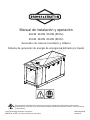
Installation and Operation Manual
29kW 40kW 50kW (50 Hz)
35kW 48kW 60kW (60 Hz)
Single Phase and Three Phase
Liquid-Cooled Standby Generator System
This generator is rated in accordance with UL (Underwriters Laboratories) 2200 (stationary engine generator
assemblies) and CSA (Canadian Standards Association) standard C22.2 No. 100-14 (motors and generators).
Copyright © Briggs & Stratton Corporation
Milwaukee, WI, USA. All rights reserved.
80022439USCN
Revision E

Not for
Reproduction
2 BRIGGSandSTRATTON.COM
Thank you for purchasing this quality-built Briggs & Stratton® generator. We are pleased that you’ve placed your confidence
in the Briggs & Stratton brand. When operated and maintained according to the instructions in this manual, your generator will
provide many years of dependable service.
This manual contains safety information to make you aware of the hazards and risks associated with standby generators and
how to avoid them.
Save these instructions for future reference.
This generator system requires professional installation before use. The installer should follow the installation instructions
completely.
Where to Find Us
You never have to look far to find support and service for your generator. Consult your Yellow Pages. There are many
authorized service dealers worldwide that provide quality service. You can also contact Technical Service by phone at
800-732-2989 between 8:00 AM and 5:00 PM central time or click on Dealer Locator at www.briggsandstratton.com, which
provides a list of authorized dealers.
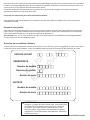
For Future Reference
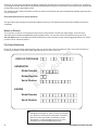
Please fill out the information below and keep with your receipt. Have this information at hand if it becomes necessary to
contact your installer or authorized dealer regarding service or repair of the unit.
DATE OF PURCHASE
GENERATOR
Model Number
Serial Number
Model Number
Model Revision
Serial Number
ENGINE
WARNING
This product can expose you to chemicals
including used engine oil, which is known to the State
of California to cause cancer, and carbon monoxide,
which is known to the State of California to cause
birth defects or other reproductive harm. For more
information go to www.P65Warnings.ca.gov.

Not for
Reproduction
3
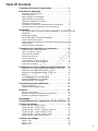
Table Of Contents
Important Safety Instructions .....................4
General Information..............................7
Equipment Description .................................... 7
Before Installation ........................................ 7
Installer Responsibilities ................................... 7
Owner Responsibilities .................................... 7
Installation Factors to Consider ............................. 8
Delivery Inspection ....................................... 8
Generator Location Considerations .......................... 8
The installation location of the generator has a direct effect on: ... 8
Installation .....................................9
TO REDUCE THE RISK OF CARBON MONOXIDE POISONING 9
Standby Generator ...................................... 10
TO REDUCE THE RISK OF FIRE .......................... 11
Other Location Requirements.............................. 12
Electrical and Fuel Inlet Locations .......................... 12
Concrete Slab .......................................... 12
Lifting the Generator ..................................... 13
Planning the Fuel Installation.....................14
Fuel Pipe Sizing......................................... 14
Type of Fuel to Use ...................................... 15
Fuel Conversion......................................... 15
Fuel Pressure........................................... 15
Power Loss ............................................ 15
Fuel Consumption (50Hz)................................. 16
Fuel Consumption (60Hz)................................. 16
Power Connections ...................................... 17
Customer Connections - Interconnect/Control ......18
Briggs & Stratton Controller Applications - 1-Ø & 3-Ø .......... 18
Intelinano Controller Applications - 3-Ø...................... 19
Intelilite Controller Applications - 1-Ø & 3-Ø .................. 20
Battery ................................................ 21
Final Installation Considerations ........................... 21
Fuel Supply System...................................... 21
Initial Start-up (No Load).................................. 22
Features and Controls...........................23
Access Panels .......................................... 23
Component Locations .................................... 24
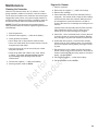
Maintenance ...................................25
Cleaning the Generator................................... 25
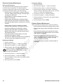
Electrical System Maintenance ............................ 26
Exhaust System Maintenance ............................. 26
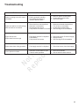
Troubleshooting................................27
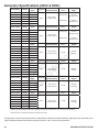
Generator Specifications (60Hz & 50Hz) ...........28
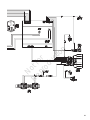
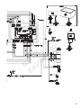
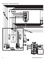
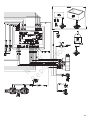
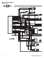
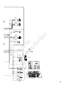
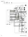
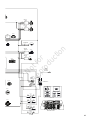
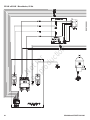
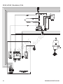
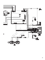
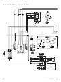
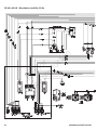
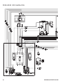
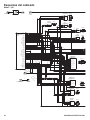
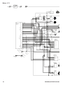
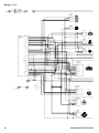
Wiring Diagrams................................29
35kW to 60kW - 1 Phase, 60Hz ............................ 30
29kW, to 50kW - 1 Phase, 50Hz ........................... 32
29kW to 60kW - 3 Phase, Intelinano, 50/60Hz ................ 34
35kW to 60kW - 1 Phase, Intelilite, 60Hz .................... 36
35kW to 60kW - 3 Phase, Intelilite, 60Hz .................... 38
35kW to 60kW - 600V, Intelilite, 60Hz ....................... 40
Wiring Schematics..............................42
Engine - 3.0L ........................................... 42
Engine - 4.3L ........................................... 44
Engine - 5.7L ........................................... 46

Not for
Reproduction
4 BRIGGSandSTRATTON.COM
Important Safety Instructions
SAVE THESE INSTRUCTIONS - This manual contains
important instructions that should be followed during
installation and maintenance of the generator and batteries.
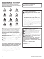
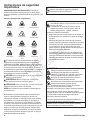
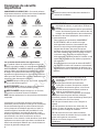
Safety Symbols and Meanings
The safety alert symbol indicates a potential personal
injury hazard. A signal word (DANGER, WARNING, or
CAUTION) is used with the alert symbol to designate a
degree or level of hazard seriousness. A safety symbol
may be used to represent the type of hazard. The signal
word NOTICE is used to address practices not related to
personal injury.
DANGER
indicates a hazard which, if not avoided, will
result in death or serious injury.
WARNING
indicates a hazard which, if not avoided, could
result in death or serious injury.
CAUTION
indicates a hazard which, if not avoided, could
result in minor or moderate injury.
NOTICE
Addresses practices not related to personal injury
The manufacturer cannot anticipate every circumstance that
might involve a hazard. The warnings in this manual, and the
tags and decals affixed to the unit are, therefore, not all-
inclusive. If you use a procedure, work method or operating
technique that the manufacturer does not specifically
recommend, you must satisfy yourself that it is safe for you
and others. You must also make sure that the procedure,
work method or operating technique that you choose does
not render the generator system unsafe.
WARNING
Running engine gives off carbon monoxide,
an odorless, colorless, poison gas.
Breathing carbon monoxide could result in death,
serious injury, headache, fatigue, dizziness,
vomiting, confusion, seizures, nausea or fainting.
• Operate this product ONLY outdoors in an area that
will not accumulate deadly exhaust gas.
• Keep exhaust gas away from any windows, doors,
ventilation intakes, soffit vents, crawl spaces, open
garage doors or other openings that can allow exhaust
gas to enter inside or be drawn into a potentially
occupied building or structure.
• Carbon monoxide detector(s) MUST be installed and
maintained indoors according to the manufacturer’s
instructions/recommendations. Smoke alarms cannot
detect carbon monoxide gas.
WARNING
Storage batteries give off explosive
hydrogen gas during recharging.
Slightest spark will ignite hydrogen and cause
explosion, resulting in death or serious injury.
Battery electrolyte fluid contains acid and is
extremely caustic.
Contact with battery contents could cause severe
chemical burns.
A battery presents a risk of electrical shock and
high short circuit current.
• DO NOT dispose of battery in a fire. Recycle battery.
• DO NOT allow any open flame, spark, heat, or lit
cigarette during and for several minutes after charging a
battery.
• DO NOT open or mutilate the battery.
• Wear protective goggles, rubber apron, rubber boots and
rubber gloves.
• Remove watches, rings, or other metal objects.
• Use tools having insulated handles.
Explosion
Fire
Electrical Shock
Rotating Parts
Hot Surface
Toxic Fumes
Chemical BurnExplosive PressureAuto Start
Crush and Cut
Hazard
Moving Parts
Read Manual
WARNING
Before using this product, read this
manual and follow all Safety Rules
and Operating Instructions.

Not for
Reproduction
5
WARNING
Propane and Natural Gas are extremely
flammable and explosive, which could cause
burns, fire or explosion resulting in death or
serious injury.
• Install the fuel supply system according to NFPA 37
and other applicable fuel-gas codes.
• Before placing the generator into service, the fuel
system lines must be properly purged and leak tested.
• After the generator is installed, you should inspect the
fuel system periodically.
• NO leakage is permitted.
• DO NOT operate engine if smell of fuel is present or
other explosive conditions exist.
• DO NOT smoke around the generator. Wipe up any
oil spills immediately. Ensure that no combustible
materials are left in the generator compartment. Keep
the area near the generator clean and free of debris.
WARNING
Exhaust heat/gases could ignite
combustibles or structures resulting in death
or serious injury.
Contact with muffler area could cause burns
resulting in serious injury.
• DO NOT touch hot parts and AVOID hot exhaust
gases.
• Allow equipment to cool before touching.
• Exhaust outlet side of weatherproof enclosure must
have at least 5 ft. (1.5m) minimum clearance from any
structure, shrubs, trees or any kind of vegetation.
• Standby generator weatherproof enclosure must be
at least 5 ft. (1.5m) from windows, doors, any wall
opening, shrubs or vegetation over 12 inches (30.5
cm) in height.
• Standby generator weatherproof enclosure must have
a minimum of 5 ft. (1.5 m) overhead clearance from
any structure, overhang, or trees.
• DO NOT place weatherproof enclosure under a deck
or other type of structure that may confine airflow.
• Smoke detector(s) MUST be installed and maintained
indoors according to the manufacturer’s instructions/
recommendations. Carbon monoxide alarms cannot
detect smoke.
• Keep at least minimum distances shown in General
Location Guidelines to insure for proper generator
cooling and maintenance clearances.
• Replacement parts must be the same and installed in
the same position as the original parts.
WARNING
Hazardous Voltage - Contact with power lines
could cause electric shock or burns, resulting in death or
serious injury.
• If lifting or hoisting equipment is used, DO NOT
contact any power lines.
• DO NOT lift or move generator without assistance.
• DO NOT lift unit by roof as damage to generator
will occur.
WARNING
Generator produces hazardous voltage.
Failure to properly ground generator could result
in electrocution.
Failure to isolate generator from utility power could result
in death or serious injury to electric utility workers due to
backfeed of electrical energy.
• DO NOT touch bare wires or bare receptacles.
• DO NOT use generator with electrical cords which are
worn, frayed, bare or otherwise damaged.
• DO NOT handle generator or electrical cords while
standing in water, while barefoot, or while hands or
feet are wet.
• If you must work around a unit while it is operating,
stand on an insulated dry surface to reduce the risk of
a shock hazard.
• DO NOT allow unqualified persons or children to
operate or service generator.
• In case of an accident caused by electrical shock,
immediately shut down the source of electrical
power and contact the local authorities. Avoid direct
contact with the victim.
• Despite the safe design of the generator, operating
this equipment imprudently, neglecting its
maintenance or being careless could cause possible
injury or death.
• Remain alert at all times while working on this
equipment. Never work on the equipment when you
are physically or mentally fatigued.
• Before performing any maintenance on the generator,
stop the generator and disconnect the negative (-)
cable at the battery.
• After your system is installed, the generator may crank
and start without warning any time there is a power
failure.

Not for
Reproduction
6 BRIGGSandSTRATTON.COM
CAUTION
Excessively high operating speeds could
result in minor injury and/or equipment damage.
Excessively low speeds impose a heavy load on generator.
• DO NOT tamper with governed speed. Generator
supplies correct rated frequency and voltage when
running at governed speed.
• DO NOT modify generator in any way.
NOTICE
Improper treatment of generator could damage it
and shorten its life.
• Use generator only for intended uses.
• If you have questions about intended use, contact your
authorized dealer.
• Operate generator only on level surfaces.
• Adequate, unobstructed flow of cooling and ventilating
air is critical to correct generator operation.
• The access panels/doors must be installed whenever
the unit is running.
• DO NOT expose generator to excessive moisture,
dust, dirt, or corrosive vapors.
• Remain alert at all times while working on this
equipment. Never work on the equipment when you
are physically or mentally fatigued.
• DO NOT start engine with air cleaner or air cleaner
cover removed.
• DO NOT insert any objects through cooling slots.
• DO NOT use the generator or any of its parts as a
step. Stepping on the unit could cause stress and
break parts. This may result in dangerous operating
conditions from leaking exhaust gases, fuel leakage,
oil leakage, etc.
• If connected devices overheat, turn them off and
disconnect them from generator.
• Shut off generator if:
-electrical output is lost;
-equipment sparks, smokes, or emits flames;
-unit vibrates excessively or makes unusual noises.
NOTICE
Exceeding the generator wattage/amperage
capacity could damage the generator and/or electrical
devices connected to it. Start generator and let engine
stabilize before connecting electrical loads.
WARNING
Moving parts could crush and cut.
Starter and other rotating parts could
entangle hands, hair, clothing, or
accessories resulting in serious injury.
• NEVER operate generator without protective
housings, covers, or guards in place.
• DO NOT wear loose clothing, jewelry or anything that
could be caught in the starter or other rotating parts.
• Tie up long hair and remove jewelry.
• Before servicing, always stop the generator and
disconnect the negative (-) cable at the battery.

Not for
Reproduction
7
General Information
For most applications, the Installation and Operation Manual
contains all the information required to properly install,
operate, and maintain the generator.
Every effort has been made to ensure that information in this
manual is accurate and current. However, we reserve the
right to change, alter, or otherwise improve the product and
this document at any time without prior notice.
Ensure that this manual is given to the owner after the
installation has been completed.
Equipment Description
This product is intended only for use as an optional
generator system to provide an alternate source of electric
power and to serve loads such as heating, refrigeration
systems, and communication systems that, when stopped
during any power outage, could cause discomfort or
inconvenience.
NOTICE Only models equipped with the DSE7310 or
ComAp Intelilite controller may qualify for a legally required
standby system as defined by NFPA 70 (NEC). For complete
information on these types of installations, consult NFPA 70
and NFPA 110.
• Legally required standby generator systems are
intended to automatically supply power to selected
loads in the event of failure of the normal source which
could create hazards or hamper rescue or fire-fighting
operations.
Before Installation
Only current licensed electrical and plumbing professionals
should attempt generator system installations. Installations
must strictly comply with all applicable codes, industry
standards, laws, and regulations.
In some areas you may need electrical permits for installing
the generator, building permits for intalling gas lines, and
permits for noise allowances. The installer should check local
codes and obtain the necessary permits before installing the
system.
The generator warranty is VOID unless the system is
installed by licensed electrical and plumbing professionals.
Installer Responsibilities
• Read and observe the safety instructions.
• Install only a UL-approved transfer switch that is
compatible with the generator.
• Read and follow the instructions in this installation and
operation manual.
• Installation must strictly comply with all applicable
codes, industry standards, laws, and regulations.
• Allow sufficient room on all sides of the generator for
maintenance and servicing.
Owner Responsibilities
• Read and follow the instructions in this installation and
operation manual.
• Follow a regular schedule for maintaining and using
the generator, as specified in this manual.
• Carbon monoxide detector(s) MUST be installed and
maintained indoors according to the manufacturer’s
instructions and recommendations. Smoke alarms
cannot detect carbon monoxide gas.
• Smoke detector(s) MUST be installed and maintained
indoors according to the manufacturer’s instructions
and recommendations. Carbon monoxide alarms
cannot detect smoke.

Not for
Reproduction
8 BRIGGSandSTRATTON.COM
Installation Factors to Consider
The illustrations shown in this manual are for typical
circumstances. They are meant to familiarize you with the
installation options available for the generator.
Federal and local codes, appearance, noise levels, fuel
types, and distances are installation factors that must be
considered. Remember that, as the distance increases
from the existing electrical service and gaseous fuel supply,
and the number of bends in the fuel supply increases,
compensations must be made for piping and wiring
materials. This is necessary to comply with local codes
and overcome electrical voltage drops and gaseous fuel
pressure drops.
The factors mentioned above will have a direct effect on the
overall price of the generator installation.
Delivery Inspection
Avoid damage from dropping, bumping, or collision with
the shipping carton. Carefully inspect the generator for any
damage that may have occurred during shipment.
If loss or damage is found at time of delivery, have the
person(s) making delivery note the loss or damage on the
freight bill and affix his signature under the consignor’s
memo of loss or damage. If the loss or damage is noted after
delivery, separate the damaged materials and contact the
carrier for claim procedures. Missing or damaged parts are
not warranted.
The standby generator system is supplied with:
• Fully-serviced coolant system
• Fully-serviced oil/lubricating system
• Flexible fuel hook-up hose
• Installation and Operation Manual
• Spare access door keys
• Touch up paint
Not Supplied:
• Carbon monoxide detector(s)
• Smoke detector(s)
• Starting battery
• Reinforced concrete pad
• Connecting wire and conduit
• Fuel supply valves/plumbing
• Crane, lifting straps, chains or cables, spreader bar
• Voltage/frequency meter
• Various special tools or equipment
Generator Location Considerations
The installation location of the generator has a direct effect
on:
1. The amount of plumbing required to fuel the generator.
2. The amount of wiring required to control and connect
the generator.
3. The safety of the installation regarding exhaust gas and
carbon monoxide hazards, fire risks, proximity to other
utilities, and exposure to weather elements.
Specific location guidelines are discussed in the next
section. The owner and installer should consult one another
to determine how the site might affect installation costs and
compliance with local codes and standards.

Not for
Reproduction
9
C
B
B
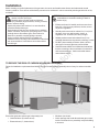
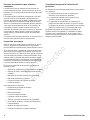
Installation
Before deciding on the final placement of the generator, the owner and installer must discuss and understand several
location guidelines. There are two critical safety concerns to be addressed - carbon monoxide poisoning and the risk of fire,
as follows:
WARNING Running engine gives off carbon monoxide, an
odorless, colorless, poison gas.
Breathing carbon monoxide could result in death,
serious injury, headache, fatigue, dizziness, vomiting, confusion,
seizures, nausea or fainting.
• Operate this product ONLY outdoors in an area that will not
accumulate deadly exhaust gas.
• Keep exhaust gas away from any windows, doors, ventilation
intakes, soffit vents, crawl spaces, open garage doors or other
openings that can allow exhaust gas to enter inside or be
drawn into a potentially occupied building or structure.
• Carbon monoxide detector(s) MUST be installed and
maintained indoors according to the manufacturer’s instructions
and recommendations. Smoke alarms cannot detect carbon
monoxide gas.
WARNING
Exhaust heat or gases could ignite
combustibles or structures resulting in death or
serious injury.
• Exhaust outlet end of standby enclosure must be at
least 5 ft (1.5 m) from any structure, shrubs, trees or
any kind of vegetation.
• Standby enclosure must be at least 5 ft (1.5 m) from
windows, doors, any wall opening, shrubs, or
vegetation over 12 inches (30.5 cm) in height.
• Standby enclosure must have at least 5 feet (1.5 m)
overhead clearance from any structure, overhang, or trees.
• DO NOT place standby enclosure under a deck or
other type of structure that may confine airflow.
• Smoke detectors MUST be installed and maintained
indoors according to the manufacturer’s instructions
and recommendations. Carbon monoxide alarms
cannot detect smoke.
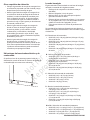
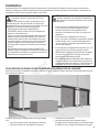
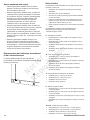
TO REDUCE THE RISK OF CARBON MONOXIDE POISONING
Follow the installation requirements listed below. The figure below illustrates potential points of entry for carbon monoxide
gas.
Ensure that generator exhaust gas is kept away from:
• Overhead doors (B, shown above)
• Entrance doors (C, shown above)
• Windows (not shown)
• Other openings that could allow exhaust gas to enter
inside or be drawn into a potentially occupied building
or structure.

Not for
Reproduction
10 BRIGGSandSTRATTON.COM
All fossil fuel burning products, such as standby
generators, emit carbon monoxide (CO) gas in the
engine exhaust. CO gas is odorless, colorless and
tasteless and is unlikely to be noticed until a person is
overcome. CO gas can kill you. It is required that the
following be included as part of the installation:
• Install the generator outdoors in an area that
will not accumulate deadly exhaust gas.
• DO NOT install the generator where exhaust
gas could accumulate and enter inside or be
drawn into a potentially occupied building or
structure.
• Nearby structures may be exposed to the engine
exhaust from the unit and must be considered
when installing the standby generator.
• Wind and air currents should be taken into
consideration when positioning the generator.
Place the generator in an area where winds will
carry the exhaust gas away from any potentially
occupied building or structure.
• DO NOT place the standby generator in any area
where leaves or debris normally accumulate.
• By law, many states require a fully operating
Carbon Monoxide (CO) detector in homes
and other structures occupied by people.
Carbon monoxide detectors MUST be
installed and maintained indoors according
to the manufacturer’s instructions and
recommendations. A carbon monoxide detector
is an electronic device that detects hazardous
levels of CO. When there is a buildup of CO,
the monitor will alert the occupants by flashing
a visual indicator light and sounding an alarm.
Smoke alarms cannot detect CO gas.
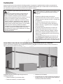
• Direct the standby generator exhaust (A, shown
below) away from or parallel to the building or
structure. DO NOT direct the generator exhaust
towards a potentially occupied building, structure,
windows, doors, ventilation intakes, soffit vents,
crawl spaces, open garage doors, or other openings
where exhaust gas could accumulate and enter
inside or be drawn into a potentially occupied
building or structure.
The engine exhaust exits the top of the housing (A).
A
Standby
Generator

Not for
Reproduction
11
A
A
B
C
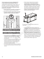
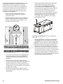
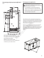
TO REDUCE THE RISK OF FIRE
Follow the installation requirements listed below. The figures below illustrate the minimum distances from structures and
vegetation to reduce the risk of fire.
The National Fire Protection Association (NFPA) standard NFPA 37 establishes criteria for minimizing the hazard of
fire during the installation and operation of stationary combustion engines. NFPA 37 limits the spacing of an enclosed
generator from openings in walls, structures and combustible materials outside the enclosure. The following generator
placement requirements are based on compliance to NFPA 37.
5 ft (1.5 m) min.
Standby
5 ft (1.5 m) min.
Exhaust
B
A
5 ft (1.5 m) min.
Standby
5 ft (1.5 m) min.
Exhaust
A
A
B
5 ft (1.5 m) min.
Standby
5 ft (1.5 m) min.
Exhaust
B
A
A
A Standby enclosure must be at least 5 ft (1.5
m) from windows, doors, any wall opening,
shrubs, or vegetation over 12 inches (30.5 cm)
in height.
B Exhaust outlet end of standby enclosure must
be at least 5 ft (1.5 m) from any structure,
shrubs, trees, or any kind of vegetation.
C Standby enclosure must have at least 5 feet
(1.5 m) overhead clearance from any structure,
overhang, or trees.
DO NOT place standby enclosure under a deck or other
type of covered structure that may confine airflow.
5 ft (1.5 m) min.
5 ft (1.5 m) min.
Standby
5 ft (1.5 m) min.
Exhaust
B
A
A

Not for
Reproduction
12 BRIGGSandSTRATTON.COM
Other Location Requirements
• Place the standby generator in a prepared location
that is flat and has provisions for water drainage.
• Install the standby generator in a location where
sump pump discharge, rain gutter down spouts, roof
run-off, landscape irrigation, or water sprinklers will
not flood the unit or spray the enclosure, or enter any
air inlet or outlet openings.
• Install the standby generator where it will not affect
or obstruct any utility services (including covered,
concealed, and underground), such as telephone,
electric, fuel (natural gas / LPG vapor), irrigation, air
conditioning, cable, septic, sewer, well, etc.
• Install the standby generator where leaves, grass,
snow, etc will not obstruct air inlet and outlet
openings. If prevailing winds will cause blowing or
drifting, a windbreak may be needed to protect the
unit.
Electrical and Fuel Inlet Locations
A through-slab power cable stub-up is recommended. The
fuel inlet connector (A) is shown for reference.
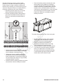
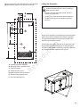
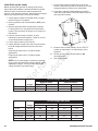
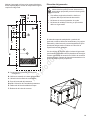
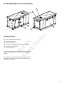
Concrete Slab
The generator must be installed on a reinforced concrete
slab, constructed as follows:
• 28 day compression strength of 3000 psi (200 MPa)
• Minimum 5” (13 cm) thick
• Minimum 6” (15 cm) wider than the standby enclosure
on all sides
• Strengthen slab with No. 6 reinforcing bars on 12” (30.5
cm) centers or 8 ga. steel wire fabric with 6” (15 cm)
centers
• Avoid placing reinforcement in the entrance stub-up
area
The following dimensions will be needed to properly size and
configure the slab. Refer to figure at right:
A - Enclosure dimensions
• 29/35kW (3.0L) = 82” (208 cm) long x 37” (94 cm) wide
• 29/35kW (4.3L) = 88” (224 cm) long x 37” (94 cm) wide
• 40/48kW = 88” (224 cm) long x 37” (94 cm) wide
• 50/60kW = 96” (244 cm) long x 37” (94 cm) wide
B - Generator mounting holes
• 29/35kW (3.0L) = 75.5” (192 cm) long x 34.25” (87 cm)
wide
• 29/35kW (4.3L) = 85” (216 cm) long x 34.25” (87 cm)
wide
• 40/48kW = 85” (216 cm) long x 34.25” (87 cm) wide
• 50/60kW = 94” (239 cm) long x 34.25” (87 cm) wide
C - Fuel inlet location
• 29/35kW (3.0L) = 40.75” (104 cm)
• 29/35kW (4.3L) = 45.5” (116 cm)
• 40/48kW = 45.5” (116 cm)
• 50/60kW = 52” (132 cm)
D - Entrance stub-up area
• 29/35kW (3.0L) = 9.25” (23 cm) long x 5.25” (13 cm)
wide
• 29/35kW (4.3L) = 10.5” (27 cm) long x 6.75” (17 cm)
wide
• 40/48kW = 10.5” (27 cm) long x 6.75” (17 cm) wide
• 50/60kW = 6.0” (15 cm) long x 5.25” (13 cm) wide
D1 x D2 - Entrance stub-up location
• 29/35kW (3.0L) = 6.0” (15 cm) x 7.75” (20 cm)
• 29/35kW (4.3L) = 8.5” (22 cm) x 7.75” (20 cm)
• 40/48kW = 8.5” (22 cm) x 7.75” (20 cm)
• 50/60kW = 16.0” (41 cm) x 7.0” (18 cm)
A

Not for
Reproduction
13
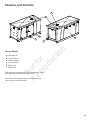
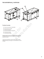
A - Standby generator enclosure
B - Mounting holes in generator base
C - Fuel inlet location
D - Entrance stub-up area
D1 x D2 - Entrance stub-up location
E - Exhaust outlet area reference
F - Concrete slab reference
WARNING
Hazardous Voltage - Contact with power lines
could cause electric shock or burns, resulting in
death or serious injury.
• If lifting or hoisting equipment is used, DO NOT
contact any power lines.
• DO NOT lift or move generator without assistance.
• DO NOT lift unit by roof as damage to generator
will occur.
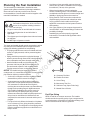
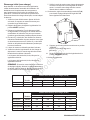
Lifting the Generator
Attach the generator to the slab at the four corner locations
(B) with masonry anchors as required by local code.
B
D
C
F
E
A
B
D2
D
D1
D
C
B
Proper tools, equipment, and qualified personnel should be
used in all phases of handling and moving the generator.
The approximate weight of the generator is listed in the
Generator Specifications section.
Use the lifting holes (G) in the base of the generator to lift
the generator onto the concrete pad. Lift the generator in
accordance with OSHA or local lifting regulations. Retouch
any chipped paint with supplied touch-up paint.
G

Not for
Reproduction
14 BRIGGSandSTRATTON.COM
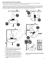
Planning the Fuel Installation
The information provided below is intended to assist
gaseous fuel system technicians in planning installations.
State and local codes may override some of these
recommendations. Consult with the local fuel supplier or fire
marshall if clarification is needed.
WARNING
Propane
and Natural Gas are extremely
flammable and explosive, which could cause
burns, fire or explosion resulting in death or
serious injury.
• LP gas is heavier than air and will settle in low areas.
• Natural gas is lighter than air and will collect in
high areas.
• The slightest spark could ignite these fuels and cause
an explosion.
• DO NOT light a cigarette or smoke.
• A minimum of one accessible, approved manual
shutoff valve (F) shall be installed in the fuel supply
line within 6 ft (180 cm) of the generator.
• Where local conditions include earthquake,
tornado, unstable ground, or flood hazards, special
consideration shall be given to increase strength and
flexibility of piping supports and connections.
• Piping must be of the correct size to maintain the
required supply pressures and volume flow under
varying generator load conditions with all gas
appliances connected to the fuel system turned on
and operating.
• Use a pipe sealant or joint compound approved for
use with NG/LP on all threaded fittings to reduce the
possibility of leakage.
• Installed piping must be properly purged and
leak tested, in accordance with applicable codes
and standards.
The owner and installer should consult one another to review
any changes to the installation plan that might arise when
applying the following guidelines for fuel plumbing.
• The piping material must conform to federal and local
codes, be rigidly mounted, and be protected against
vibration.
• Piping should be protected from physical damage
where it passes through flower beds, shrub beds, and
other cultivated areas where damage could occur.
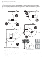
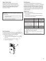
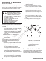
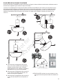
• Install a flexible hose (B, at right) between the
generator fuel inlet port (A) and the rigid piping to
prevent thermal expansion and contraction from
causing excessive stress on the piping material.
NOTICE
The flexible fuel pipe is not to be installed
underground or in contact with the ground. The entire flexible
pipe must be visible for periodic inspection.
• A union (C) or flanged connection shall be provided
downstream to permit removal of controls.
• A manometer test port (D) should be installed for
vapor fuels. The port permits temporary installation
of a manometer to check whether the engine is
receiving the correct fuel pressure to operate efficiently
throughout its operating range. A digital manometer
(P/N 19495) is available at your service center for
vapor fuels only. For liquid propane any pressure
measurement instrument rated for liquid propane and
350 psi can be used. When the initial test runs are
completed, the manometer is removed and the port is
plugged.
• For vapor fuels only: Where the formation of hydrates
or ice is known to occur, piping should be protected
against freezing. The termination of hard piping should
include a sediment trap (E) where condensate is not
likely to freeze.
A
B
C
D
E
F
A - Generator Fuel Inlet
B - Flexible Fuel Hose
C - Union Fitting
D - Manometer Test Port
E - Sediment Trap (Vapor Fuels Only)
F - Manual Shut-off Valve
Fuel Pipe Sizing
NFPA 54 and 58 are common resources. The installer
should consider the specific gravity of gas, compensate for
a nominal amount of restriction from bends and fittings, and
refer to federal and local codes for guidance.

Not for
Reproduction
15
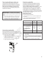
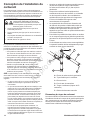
Fuel Conversion
The engine was set at the factory to run on natural gas (NG).
To convert the engine to run on liquid propane (LP Vapor), or
to change back to NG later, follow these steps:
1. Open the controller door.
2. Locate fuel selector switch on side of circuit breaker
enclosure.
3. Move the switch (A, below) to LP or NG.
4. Close the controller door.
A
WARNING
Fuel is extremely flammable and explosive,
which could cause burns, fire or explosion resulting in death
or serious injury.
• The generator is equipped with automatic safety gas
“fuel shut-off” valves.
• DO NOT operate the equipment if the “fuel shut-off”
valves are missing or inoperative.
Type of Fuel to Use
An important consideration affecting the entire
installation is the type of fuel to be supplied. For
proper engine function, use clean, dry fuel, free of
moisture or any particulate material. Using fuels
outside the recommended values may cause
performance problems.
Fuel Pressure
Fuel supply pressure at the generator fuel inlet port (or
vaporizer test port) should be 7 - 11 inch WC (17 - 28 mBar) at
full load and with all gas appliances turned on and operating.
Maximum pressure drop from static (engine not running) to
full load is 0.5 inch WC (1.3 mbar). Maximum pressure with
engine OFF at no load is 13.85 inch WC (34.5 mbar). Liquid
propane fuel pressure at generator inlet should be 100-250
psi (690-1725 kPa).
Power Loss
Engine power will decrease:
• 1.5% for every 10°F (5.6°C) above rated temperature
of 77°F (25°C).
• 2.5% for every 1,000 ft (305 m) above rated altitude of
1,200 ft (366 m) above sea level.
Physical Properties LP Vapor Natural Gas
Normal Atmospheric State Gas Gas
Boiling Point (°F): -44 -259
Heating Value:
BTU per gallon (Net LHV *)
BTU per gallon (gross **)
BTU per cubic feet (gas)
83,340
91,547
2,500
63,310
1,000
Density *** 36.39 57.75
Weight † 4.24 2.65
* LHV (Low Heat Value) is the more realistic rating.
** Gross heat value does not consider heat lost in the
form of water during combustion.
*** Density is given in “Cubic Feet of Gas per Gallon of
Liquid”.
† Weight is given in “Pounds per Gallon of Liquid”.

Not for
Reproduction
16 BRIGGSandSTRATTON.COM
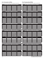
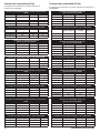
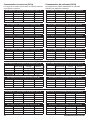
Fuel Consumption (50Hz)
Shown below are the estimated fuel supply requirements.
Fuel Consumption (60Hz)
Shown below are the estimated fuel supply requirements.
Series 29000 (3.0L) LP Vapor Fuel Consumption
Full Load 1/2 Load Exercise
BTU/hr 365000 230000 70000
ft³/hr 146 92 28
m³/hr 4.2 2.6 0.8
Gal/hr (liquid) 4.0 2.6 0.8
Series 35000 (3.0L) LP Vapor Fuel Consumption
Full Load 1/2 Load Exercise
BTU/hr 371000 241000 130000
ft³/hr 149 97 52
m³/hr 4.2 2.8 1.5
Gal/hr (liquid) 4.1 2.7 1.5
Series 29000 (3.0L) NG Fuel Consumption
Full Load 1/2 Load Exercise
BTU/hr 286000 179000 89000
ft³/hr 286 179 89
m³/hr 8.1 5.1 2.6
Series 35000 (3.0L) NG Fuel Consumption
Full Load 1/2 Load Exercise
BTU/hr 336000 215000 108000
ft³/hr 336 215 108
m³/hr 9.5 6.1 3.1
Series 29000 (4.3L) LP Vapor Fuel Consumption
Full Load 1/2 Load Exercise
BTU/hr 349000 225000 106000
ft³/hr 140 90 43
m³/hr 4.0 2.6 1.2
Gal/hr (liquid) 3.9 2.5 1.2
Series 35000 (4.3L) LP Vapor Fuel Consumption
Full Load 1/2 Load Exercise
BTU/hr 409000 262000 137000
ft³/hr 164 105 55
m³/hr 4.7 3.0 1.6
Gal/hr (liquid) 4.5 2.9 1.5
Series 29000 (4.3L) NG Fuel Consumption
Full Load 1/2 Load Exercise
BTU/hr 356000 222000 120000
ft³/hr 356 222 120
m³/hr 10.1 6.3 3.4
Series 35000 (4.3L) NG Fuel Consumption
Full Load 1/2 Load Exercise
BTU/hr 405000 258000 146000
ft³/hr 405 258 146
m³/hr 11.5 7.3 4.2
Series 40000 (4.3L) NG Fuel Consumption
Full Load 1/2 Load Exercise
BTU/hr 428000 256000 118000
ft³/hr 428 256 118
m³/hr 12.2 7.3 3.4
Series 48000 (4.3L) NG Fuel Consumption
Full Load 1/2 Load Exercise
BTU/hr 511000 328000 181000
ft³/hr 511 328 181
m³/hr 14.5 9.3 5.2
Series 40000 (4.3L) LP Vapor Fuel Consumption
Full Load 1/2 Load Exercise
BTU/hr 682500 470000 183750
ft³/hr 273 188 74
m³/hr 7.7 5.3 2.1
Gal/hr (liquid) 7.5 5.1 2.0
Series 48000 (4.3L) LP Vapor Fuel Consumption
Full Load 1/2 Load Exercise
BTU/hr 533000 337000 165000
ft³/hr 214 135 66
m³/hr 6.1 3.9 1.9
Gal/hr (liquid) 5.9 3.7 1.9
Series 50000 (5.7L) LP Vapor Fuel Consumption
Full Load 1/2 Load Exercise
BTU/hr 729000 500000 198000
ft³/hr 292 200 80
m³/hr 8.3 5.7 2.3
Gal/hr (liquid) 8.0 5.5 2.2
Series 60000 (5.7L) LP Vapor Fuel Consumption
Full Load 1/2 Load Exercise
BTU/hr 875000 644000 264000
ft³/hr 350 258 106
m³/hr 10.0 7.3 3.0
Gal/hr (liquid) 9.6 7.1 2.9
Series 50000 (5.7L) NG Fuel Consumption
Full Load 1/2 Load Exercise
BTU/hr 669000 462000 213000
ft³/hr 669 462 213
m³/hr 19.0 13.1 6.1
Series 60000 (5.7L) NG Fuel Consumption
Full Load 1/2 Load Exercise
BTU/hr 753000 561000 264000
ft³/hr 753 561 264
m³/hr 21.4 15.9 7.5

Not for
Reproduction
17
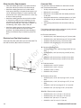
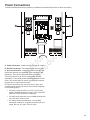
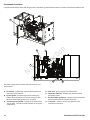
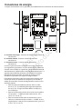
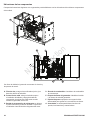
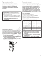
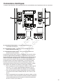
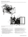
Power Connections
Compare this illustration with the generator to familiarize yourself with the location of these connections.
B
C
A A
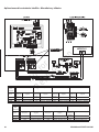
A - Power Connection - Power connection to transfer switch.
B - Neutral Connection - Connect to transfer switch neutral.
C - Ground Connection - Connect to transfer switch ground.
Ground the generator per applicable codes, standards, and
regulations. There are two generator GND lug locations.
The location shown by (C, above) should suffice for most
applications. The second generator GND lug is located on the
frame. This should ONLY be used for a ground rod located at
the generator, if required by local codes.
For system connections such as remote start, e-stops, and
controller inputs and outputs, refer to the connection diagrams
on the following pages.
• For power output connection, use 75°C (167°F) wire
rated for ambient temperature of 40°C (104°F) per NEC
Tables 310.15(B)(16) and 310.15(B)(2)(a).
• For utility circuit connection, use #14 AWG minimum 600
volt, 167-194°F (75-90°C) wire.
• For transfer switch communication, use #18 AWG
twisted pair conductors, no greater than 200 ft (60 m) in
length, 600 volt, 167-194°F (75-90°C) wire.

Not for
Reproduction
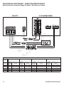
18 BRIGGSandSTRATTON.COM
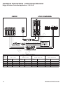
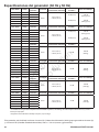
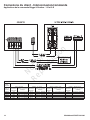
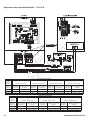
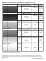
Generator Circuit Breaker
Voltage
- Phase -
Frequency
230V - 1Ø - 50Hz 120/240V - 1Ø - 60Hz 120/208V - 3Ø Wye - 60Hz 120/240V - 3Ø Delta - 60Hz
Power
Node
Breaker
Ampacity
Lug Wire Range
Breaker
Ampacity
Lug Wire Range
Breaker
Ampacity
Lug Wire Range
Breaker
Ampacity
Lug Wire Range
20/25kW 90A 125A Cu/Al: #2 - 300kcmil 90A Cu: #6 - 2/0 Al: #4 - 2/0 80A Cu/Al: #3 - 500kcmil
25/30kW 125A Cu/Al: #2 - 300kcmil 150A Cu/Al: #2 - 300kcmil 110A Cu: #3 - 3/0 Al: #1 - 3/0 90A Cu: #6 - 2/0 Al: #4 - 2/0
29/35kW 150A Cu/Al: #2 - 300kcmil 150A Cu/Al: #2 - 300kcmil
40/48kW 175A Cu/Al: #2 - 300kcmil 200A Cu/Al: #2 - 300kcmil
50/60kW 225A Cu/Al: #2 - 300kcmil 300A Cu/Al: #6 - 600kcmil
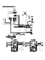
Briggs & Stratton Controller Applications - 1-Ø & 3-Ø
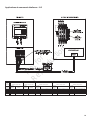
Customer Connections - Interconnect/Control

Not for
Reproduction
19
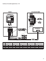
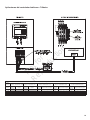
Generator Circuit Breaker
Voltage
- Phase -
Frequency
120/208V - 3Ø Wye - 60 Hz 120/240V - 3Ø Delta - 60Hz 220/380V - 3Ø Wye - 50Hz 240/416V - 3Ø Wye - 60Hz 277/480V - 3Ø Wye - 60Hz
Power
Node
Breaker
Ampacity
Lug Wire Range
Breaker
Ampacity
Lug Wire Range
Breaker
Ampacity
Lug Wire Range
Breaker
Ampacity
Lug Wire Range
Breaker
Ampacity
Lug Wire Range
20/25kW 40A Cu: #14 - #3 Al: #12 - #1 40A Cu: #14 - #3 Al: #12 - #1 40A Cu: #14 - #3 Al: #12 - #1
25/30kW 50A Cu: #14 - #3 Al: #12 - #1 50A Cu: #14 - #3 Al: #12 - #1 50A Cu: #14 - #3 Al: #12 - #1
29/35kW 125A Cu/Al: #4 - 300kcmil 110A Cu/Al: #4 - 300kcmil 60A Cu: #14 - #3 Al: #12 - #1 70A Cu: #6 - 2/0 Al: #4 - 2/0 60A Cu: #14 - #3 Al: #12 - #1
40/48kW 200A Cu/Al: #4 - 300kcmil 175A Cu/Al: #4 - 300kcmil 100A Cu: #3 - 3/0 Al: #1 - 3/0 100A Cu: #3 - 3/0 Al: #1 - 3/0 90A Cu: #6 - 2/0 Al: #4 - 2/0
50/60kW 225A Cu/Al: #4 - 300kcmil 200A Cu/Al: #4 - 300kcmil 100A Cu/Al: #4 - 300kcmil 125A Cu/Al: #4 - 300kcmil 100A Cu: #3 - 3/0 Al: #1 - 3/0
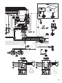
Intelinano Controller Applications - 3-Ø

Not for
Reproduction
20 BRIGGSandSTRATTON.COM
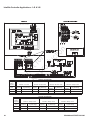
Generator Circuit Breaker
Voltage
- Phase -
Frequency
120/240V - 1Ø - 60Hz 120/208V - 3Ø Wye - 60Hz 120/240V - 3Ø Delta - 60Hz 220/380V - 3Ø Wye - 50Hz
Power
Node
Breaker
Ampacity
Lug Wire Range
Breaker
Ampacity
Lug Wire Range
Breaker
Ampacity
Lug Wire Range
Breaker
Ampacity
Lug Wire Range
20/25kW 150A Cu/Al: #2 - 300kcmil 125A Cu/Al: #4 - 300kcmil 110A Cu/Al: #4 - 300kcmil 60A Cu: #6 - 2/0 Al: #4 - 2/0
25/30kW 225A Cu/Al: #2 - 300kcmil 200A Cu/Al: #4 - 300kcmil 175A Cu/Al: #4 - 300kcmil 100A Cu: #3 - 3/0 Al: #1 - 3/0
29/35kW 300A Cu/Al: #6 - 600kcmil 225A Cu/Al: #4 - 300kcmil 200A Cu/Al: #4 - 300kcmil 125A Cu/Al: #4 - 300kcmil
Generator Circuit Breaker
Voltage
- Phase -
Frequency
240/416V - 3Ø Wye - 60Hz 277/480V - 3Ø Wye - 60Hz 347/600V - 3Ø Wye - 60Hz
Power
Node
Breaker
Ampacity
Lug Wire Range
Breaker
Ampacity
Lug Wire Range
Breaker
Ampacity
Lug Wire Range
20/25kW 70A Cu: #6 - 2/0 Al: #4 - 2/0 60A Cu: #14 - #3 Al: #12 - #1 45A Cu: #14 - #3 Al: #12 - #1
25/30kW 100A Cu: #3 - 3/0 Al: #1 - 3/0 90A Cu: #6 - 2/0 Al: #4 - 2/0 70A Cu: #6 - 2/0 Al: #4 - 2/0
29/35kW 125A Cu/Al: #4 - 300kcmil 100A Cu: #3 - 3/0 Al: #1 - 3/0 90A Cu: #6 - 2/0 Al: #4 - 2/0
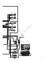
Intelilite Controller Applications - 1-Ø & 3-Ø
La page est en cours de chargement...
La page est en cours de chargement...
La page est en cours de chargement...
La page est en cours de chargement...
La page est en cours de chargement...
La page est en cours de chargement...
La page est en cours de chargement...
La page est en cours de chargement...
La page est en cours de chargement...
La page est en cours de chargement...
La page est en cours de chargement...
La page est en cours de chargement...
La page est en cours de chargement...
La page est en cours de chargement...
La page est en cours de chargement...
La page est en cours de chargement...
La page est en cours de chargement...
La page est en cours de chargement...
La page est en cours de chargement...
La page est en cours de chargement...
La page est en cours de chargement...
La page est en cours de chargement...
La page est en cours de chargement...
La page est en cours de chargement...
La page est en cours de chargement...
La page est en cours de chargement...
La page est en cours de chargement...
La page est en cours de chargement...
La page est en cours de chargement...
La page est en cours de chargement...
La page est en cours de chargement...
La page est en cours de chargement...
La page est en cours de chargement...
La page est en cours de chargement...
La page est en cours de chargement...
La page est en cours de chargement...
La page est en cours de chargement...
La page est en cours de chargement...
La page est en cours de chargement...
La page est en cours de chargement...
La page est en cours de chargement...
La page est en cours de chargement...
La page est en cours de chargement...
La page est en cours de chargement...
La page est en cours de chargement...
La page est en cours de chargement...
La page est en cours de chargement...
La page est en cours de chargement...
La page est en cours de chargement...
La page est en cours de chargement...
La page est en cours de chargement...
La page est en cours de chargement...
La page est en cours de chargement...
La page est en cours de chargement...
La page est en cours de chargement...
La page est en cours de chargement...
La page est en cours de chargement...
La page est en cours de chargement...
La page est en cours de chargement...
La page est en cours de chargement...
La page est en cours de chargement...
La page est en cours de chargement...
La page est en cours de chargement...
La page est en cours de chargement...
La page est en cours de chargement...
La page est en cours de chargement...
La page est en cours de chargement...
La page est en cours de chargement...
La page est en cours de chargement...
La page est en cours de chargement...
La page est en cours de chargement...
La page est en cours de chargement...
La page est en cours de chargement...
La page est en cours de chargement...
La page est en cours de chargement...
La page est en cours de chargement...
La page est en cours de chargement...
La page est en cours de chargement...
La page est en cours de chargement...
La page est en cours de chargement...
La page est en cours de chargement...
La page est en cours de chargement...
La page est en cours de chargement...
La page est en cours de chargement...
La page est en cours de chargement...
La page est en cours de chargement...
La page est en cours de chargement...
La page est en cours de chargement...
La page est en cours de chargement...
La page est en cours de chargement...
La page est en cours de chargement...
La page est en cours de chargement...
La page est en cours de chargement...
La page est en cours de chargement...
La page est en cours de chargement...
La page est en cours de chargement...
La page est en cours de chargement...
La page est en cours de chargement...
La page est en cours de chargement...
La page est en cours de chargement...
La page est en cours de chargement...
La page est en cours de chargement...
La page est en cours de chargement...
La page est en cours de chargement...
La page est en cours de chargement...
La page est en cours de chargement...
La page est en cours de chargement...
La page est en cours de chargement...
La page est en cours de chargement...
La page est en cours de chargement...
La page est en cours de chargement...
La page est en cours de chargement...
La page est en cours de chargement...
La page est en cours de chargement...
La page est en cours de chargement...
La page est en cours de chargement...
La page est en cours de chargement...
La page est en cours de chargement...
La page est en cours de chargement...
La page est en cours de chargement...
La page est en cours de chargement...
La page est en cours de chargement...
La page est en cours de chargement...
La page est en cours de chargement...
-
 1
1
-
 2
2
-
 3
3
-
 4
4
-
 5
5
-
 6
6
-
 7
7
-
 8
8
-
 9
9
-
 10
10
-
 11
11
-
 12
12
-
 13
13
-
 14
14
-
 15
15
-
 16
16
-
 17
17
-
 18
18
-
 19
19
-
 20
20
-
 21
21
-
 22
22
-
 23
23
-
 24
24
-
 25
25
-
 26
26
-
 27
27
-
 28
28
-
 29
29
-
 30
30
-
 31
31
-
 32
32
-
 33
33
-
 34
34
-
 35
35
-
 36
36
-
 37
37
-
 38
38
-
 39
39
-
 40
40
-
 41
41
-
 42
42
-
 43
43
-
 44
44
-
 45
45
-
 46
46
-
 47
47
-
 48
48
-
 49
49
-
 50
50
-
 51
51
-
 52
52
-
 53
53
-
 54
54
-
 55
55
-
 56
56
-
 57
57
-
 58
58
-
 59
59
-
 60
60
-
 61
61
-
 62
62
-
 63
63
-
 64
64
-
 65
65
-
 66
66
-
 67
67
-
 68
68
-
 69
69
-
 70
70
-
 71
71
-
 72
72
-
 73
73
-
 74
74
-
 75
75
-
 76
76
-
 77
77
-
 78
78
-
 79
79
-
 80
80
-
 81
81
-
 82
82
-
 83
83
-
 84
84
-
 85
85
-
 86
86
-
 87
87
-
 88
88
-
 89
89
-
 90
90
-
 91
91
-
 92
92
-
 93
93
-
 94
94
-
 95
95
-
 96
96
-
 97
97
-
 98
98
-
 99
99
-
 100
100
-
 101
101
-
 102
102
-
 103
103
-
 104
104
-
 105
105
-
 106
106
-
 107
107
-
 108
108
-
 109
109
-
 110
110
-
 111
111
-
 112
112
-
 113
113
-
 114
114
-
 115
115
-
 116
116
-
 117
117
-
 118
118
-
 119
119
-
 120
120
-
 121
121
-
 122
122
-
 123
123
-
 124
124
-
 125
125
-
 126
126
-
 127
127
-
 128
128
-
 129
129
-
 130
130
-
 131
131
-
 132
132
-
 133
133
-
 134
134
-
 135
135
-
 136
136
-
 137
137
-
 138
138
-
 139
139
-
 140
140
-
 141
141
-
 142
142
-
 143
143
-
 144
144


Simplicity 076130-00 Manuel utilisateur
- Catégorie
- Groupes électrogènes
- Taper
- Manuel utilisateur
dans d''autres langues
- English: Simplicity 076130-00 User manual
- español: Simplicity 076130-00 Manual de usuario
Documents connexes
-
Simplicity 076350-02 Manuel utilisateur
-
Simplicity 076552-01 Manuel utilisateur
-
Simplicity 076830-00 Manuel utilisateur
-
-
-
-
-