Bosch US12 Guide d'installation
- Catégorie
- Chauffe-eau
- Taper
- Guide d'installation

en Installation and Operating instructions 2
es Instrucciones de instalación y funcionamiento 18
fr Instructions d'installation et d'utilisation 35
Electric water heaters
Tronic 3000 C Pro
Model US12
6 720 647 088 (2011/09) US
IMPORTANT: This booklet should be given to the customer after installation and demonstration.
For Service & Installation contact:
BOSCH Thermotechnology Corp.
50 Wentworth Avenue, Londonderry
NH 03053 - 800-798-8161
www.bosch-climate.us

2 | Table of contents US
6 720 647 088 (2011/09)
Table of contents
1 Explanation of Symbols and Important Safety
Instructions . . . . . . . . . . . . . . . . . . . . . . . . . . . . . 3
1.1 Explanation of symbols . . . . . . . . . . . . . . . . 3
1.2 Important Safety Instructions . . . . . . . . . . . 3
2 Information about the heater . . . . . . . . . . . . . . . . 4
2.1 Disclaimer . . . . . . . . . . . . . . . . . . . . . . . . . . 4
2.1.1 Approval number . . . . . . . . . . . . . . . . . . . . 4
2.2 Technical identification code . . . . . . . . . . . 4
2.3 Model name and number identification . . . 4
2.4 Package contents . . . . . . . . . . . . . . . . . . . . 4
2.5 General description . . . . . . . . . . . . . . . . . . 5
2.6 Function . . . . . . . . . . . . . . . . . . . . . . . . . . . 6
3 Regulations . . . . . . . . . . . . . . . . . . . . . . . . . . . . . . 7
4 Installation . . . . . . . . . . . . . . . . . . . . . . . . . . . . . . 8
4.1 Important information . . . . . . . . . . . . . . . . 8
4.1.1 Freeze prevention . . . . . . . . . . . . . . . . . . . . 8
4.2 Installing the Tronic 3000C Pro . . . . . . . . . 8
4.3 Water connections . . . . . . . . . . . . . . . . . . . 9
4.3.1 Water quality . . . . . . . . . . . . . . . . . . . . . . . . 9
4.4 Electrical connections . . . . . . . . . . . . . . . 10
4.5 Securing the unit to the wall . . . . . . . . . . 11
4.5.1 Deciding the position . . . . . . . . . . . . . . . . 11
4.5.2 Deciding the wiring route . . . . . . . . . . . . . 11
4.5.3 Mounting on the wall . . . . . . . . . . . . . . . . 12
5 Starting up the Tronic 3000C Pro . . . . . . . . . . . 13
5.1 Sink . . . . . . . . . . . . . . . . . . . . . . . . . . . . . . 13
5.2 Adjusting the flow . . . . . . . . . . . . . . . . . . . 13
5.3 Appendix Flow vs. Temperature Setting
Guide . . . . . . . . . . . . . . . . . . . . . . . . . . . . 14
6 Troubleshooting . . . . . . . . . . . . . . . . . . . . . . . . . 15
6.1 For the Installer . . . . . . . . . . . . . . . . . . . . 15
6.2 For the User . . . . . . . . . . . . . . . . . . . . . . . 16
7 Interior components and parts list . . . . . . . . . . 17

Explanation of Symbols and Important Safety Instructions | 3US
6 720 647 088 (2011/09)
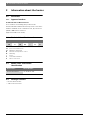
1 Explanation of Symbols and Important Safety Instructions
1.1 Explanation of symbols
Warnings
Signal words at the beginning of a warning are used to
indicate the type and seriousness of the ensuing risk if
measures for minimizing damage are not taken.
• NOTE indicates that minor damage to property may
occur.
• CAUTION indicates possible minor to medium
personal injury.
• WARNING indicates possible severe personal injury.
• DANGER indicates that severe personal injury may
occur.
Important information
Additional symbols
1.2 Important Safety Instructions
When using this electrical equipment, basic safety
precautions should always be followed, including the
following:
B Read and follow all instructions.
B This appliance must be grounded.
B Disconnect this product from the electrical supply
before cleaning, servicing or removing the cover.
B To reduce the risk of injury, close supervision is
necessary when the product is used near children or
elderly persons.
B Warning: Indoor installation only, where it will NOT be
exposed to freezing.
B Warning: Do not install a check valve or any other
types of back flow preventer within six feet of the cold
water inlet.
B The electrical installation must conform to current
National Electrical Codes.
B Warning: Do not switch the heater on if you suspect
that it may be frozen. Wait until you are sure that it
has completely thawed cut.
B The Tronic 3000C Pro is designed to heat potable cold
water for domestic purposes. Contact Bosch
Thermotechnology before specifying or installing the
appliance in any other application.
Additional Canadian Safety Instructions
• A green terminal (or wire connector marked "G", "GR",
"GROUND", or "GROUNDING") is provided within the
control box. To reduce the risk of electric shock,
connect this terminal or connector to the grounding
terminal of the electric service of supply panel with a
continuous copper wire in accordance with the
Canadian Electrical Code, Part I.
• This product shall be protected by a Class A ground
fault circuit interrupter.
Safe these instructions
B Keep this guide in a safe place once your Tronic
3000C Pro unit has been installed.
B You may need to refer to it for general instructions or
future maintenance.
Warnings are indicated in the text by a
warning triangle and a gray background.
In case of danger due to electric shock, the
exclamation point on the warning triangle is
replaced with a lightning symbol.
Important information that presents no risk
to people or property is indicated with this
symbol. It is separated by horizontal lines
above and below the text.
Symbol Meaning
B Sequence of steps
→ Cross-reference to other points in this
document or to other documents
• Listing/list entry
– Listing/list entry (2nd level)
Table 1

4 | Information about the heater US
6 720 647 088 (2011/09)
2 Information about the heater
2.1 Disclaimer
2.1.1 Approval number
Commonwealth of Massachusetts
As a condition of installing this product in the
Commonwealth of Massachusetts a pressure relief valve
shall be installed on the cold water side, by a licensed
plumber MGL 142 Section 19.
(Approval number: P1-09-25).
2.2 Technical identification code
US Electronic Instantaneous
12 Maximum output (kW)
M Mechanical temperature control
W Wall hung
I Indoor
H Horizontal installation
B Water connections
2.3 Model name and number
identification
2.4 Package contents
• Electric water heater
• 4 No. 8 wood screws
US 12 M W I H B
Table 2
Model Name Model Number
Tronic 3000 C Pro US 12 M W I H B
Table 3

Information about the heater | 5US
6 720 647 088 (2011/09)
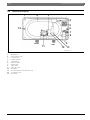
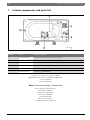
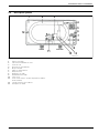
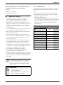
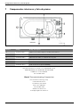
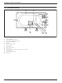
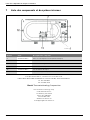
2.5 General description
Fig. 1
1 Mouting hole
2 Heat exchanger tube
3 Control P.C.B
4 Heating elements
5 Terminal block
6 Cable rear entry
7 Ground stud
8 Cable clamp
9 Cable side entry
10 Neon light
11 Hi temp thermal cut-out (manual re-set)
12 Cover fixing screw
13 Flow switch
6720646914-01.1V
1 2
3
4
5
6
7
8
9
10
11
12
13
Outlet
Inlet

6 | Information about the heater US
6 720 647 088 (2011/09)
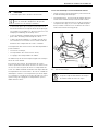
2.6 Function
• Water comes in through the cold water inlet.
• The flow switch senses water is passing through the
unit. If it detects more than the pre-set level, the
unit’s heating the elements switch on. This is shown
by the neon light glowing.
• The water is heated instantly as it pas ses through the
copper heat exchanger tube.
• The unit is Thermostatic i.e. it will switch the
elements on and off in order to maintain a constant
outlet temperature.
The temperature of the water coming out of the unit
depends on:
• The voltage of the electrical supply,
• The temperature of the incoming water.
• The setting of the temperature dial.
A high flow rate can also negatively effect the hot water
temperature.
Depending on the region of the country, the temperature
of the water supply can vary from 40°F in winter to about
70°F in the summer, with an average of about 50°F.
Extreme weather conditions can cause the inlet
temperature to go outside these boundaries, making it
necessary to adjust the Temperature Adjustment
Spindle and/or the inlet water flow
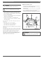
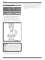
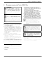
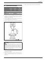
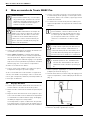
Manual reset thermal cut-out
• The unit has one double pole thermal cut out which is
mounted on the heat exchanger tube.
• When tripped the cut out needs to be reset manually
inside the unit.
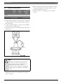
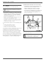
• The cut-out will trip only in exceptional circumstances
(Fig. 2). Call your service person or Bosch
Thermotechnology Corp. if this happens frequently.
Fig. 2
A Thermal cut out
The heater is designed for cold water supply
only. Do not supply with pre-heated water.
WARNING:
B Always switch off the electrical supply to
the unit before you remove the cover.

Regulations | 7US
6 720 647 088 (2011/09)
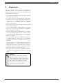
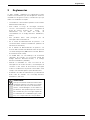
3 Regulations
Any local by-laws and regulations pertaining to
installation and use of electric water heater appliances
must be observed. Please refer to the laws that should
be attended in your country.
• The electrical installation must conform to current
National Electrical Codes.
• To reduce the risk of electrical shock, connect this
terminal or connector to the grounding terminal of the
electrical service of supply panel with a continuous
copper wire in accordance with the Canadian
Electrical Code, Part I.
• This product shall be protected by a Class A ground
fault circuit interrupter.
• In the Commonwealth of Massachusetts a licensed
plumber or electrician must perform the installation.
(Approval number: P1-09-25).
• In the Commonwealth of Massachusetts a pressure
relief valve shall be installed on the cold water side by
a licensed plumber. (MGL 142 Section 19, Approval
number P1-09-25).
• The unit must be wired by a qualified electrician, in
accordance with the current version of the National
Electrical Code US) or Canadian Electric Code
(Canada).
• When the heater is not within sight of the electrical
circuit breakers, a circuit breaker lockout or
additional local means of disconnection for all non-
grounded conductors must be provided that is within
sight of the appliance. (Ref NEC 422.31.).
• The power cable size and the installation must be in
accordance with the Canadian Electrical Code, C22.1-
02.
WARNING:
California Proposition 65 lists chemical
substances known to the state to cause
cancer, birth defects, death, serious illness
or other reproductive harm. This product
may contain such substances, be their
origin from fuel combustion (gas, oil) or
components of the product itself.

8 | Installation US
6 720 647 088 (2011/09)
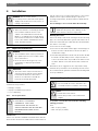
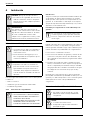
4 Installation
4.1 Important information
Please follow these instructions. Failure to follow
instructions may result in:
• Damage or injury.
• Improper installation/operation.
• Loss of warranty.
4.1.1 Freeze prevention
Introduction
Please note that the installation manual states that the
water heater must not be installed in a location where it
may be exposed to freezing temperatures. If the heater
must be left in a space that is likely to experience
freezing temperatures, all water must be drained from
the heater.
Freeze damage is not covered under the warranty.
Draining the heater
Due to the shape of the heat exchangers and connecting
pipe, it is extremely difficult to get all of the water out of
the heater. Follow the procedure below to best minimize
the chance of freezing:
B Disconnect electric supply.
B Disconnect cold and hot water pipes from fittings on
bottom of heater. Allow water to drain out (have a
catch basin ready).
B After allowing all water to drain out, the heater should
be blown out with low pressure compressed air to
remove as much water as possible from water heater
modules. Bursts of air work better than continuous
flow.
Remember, these suggestions are only made to help
minimize the potential for freeze damage and are not to
be construed as the guaranteed method for dealing with
freeze possibilities.
4.2 Installing the Tronic 3000C Pro
To operate correctly the unit needs the following
running pressures:
Sink
• Min: 10 psi (0,7 bar)
• Max: 150 psi (10,3 bar)
DANGER: Risk of electric shock!
B For safety reasons, disconnect the power
supply to the heater before any service or
testing is performed.
WARNING:
B This heater must be electrically grounded
in accordance with the most recent
edition of the National Electrical Code.
NFPA 70. In Canada, all electrical wiring
to the heater must be in accordance with
local codes and the Canadian Electrical
Code, CSA C22.1 Part 1.
DANGER:
B The installation must only be performed
by a qualified person in accordance with
these instructions.
B Bosch Thermotechnology Corp. is not
responsible for improperly installed
appliances.
WARNING:
B The heater must only be mounted in a
vertical position with the water fittings
located at the bottom of the heater.
Under no circumstances should the
heater be mounted differently.
WARNING:
B ELECTRICITY IS EXTREMELY
DANGEROUS. TAKE EXTRA
PRECAUTIONS AND ENSURE ALL
CIRCUIT BREAKERS ARE OFF BEFORE
PERFORMING ANY WORK TO THE
HEATER.
Use of agents like anti-freeze are not
allowed as they may cause damage to the
water heater’s internal components.
WARNING:
B Do not install the Tronic 3000C Pro in a
room where there is a chance of freezing.
NOTE:
B Read entire instructions.
B Check the pressure of the main water
supply.

Installation | 9US
6 720 647 088 (2011/09)
4.3 Water connections
B The unit should be connected directly to the main
cold water supply and not to pre- heated water. The
unit should be installed with service valves on both
the inlet and outlet. These valves can be used to turn
off the water supply to the unit if it needs servicing, or
to reduce the water flow if it is too high.
B We recommend that you use ½" copper or high
pressure flex connections.
B Use Teflon tape for sealing pipe threads. Do NOT use
pipe dope.
B Remember to keep the hot water pipe runs as short
as possible. In some cases it may be worth fitting a
second unit to serve an additional fixture.
B The inlet and outlet are clearly marked on the unit.
They each have a ½" NPT connector.
B If the unit is to supply more than one sink, a similarly
flow restricted aerator should be used at each tap. If
not, the highest flowing outlet will take all the water
under dual usage.
B If the unit is to supply a sink, we recommend that you
use aerators, which you can get from your local
distributor/dealer.
B After the unit has been plumbed in, and before you
wire it, flush it with water to remove any debris or
loose particles. Failure to do so may make the unit
inoperable.
4.3.1 Water quality
Water quality can have an impact on appliance longevity
and may not be covered under the manufacturer's
warranty.
B For water analysis data call your local water
department, or if on a well, have well water analyzed
periodically.
If water quality exceeds one or more of the values
specified below, Bosch recommends consulting a
local water treatment professional for water
softening/conditioning options.
As a condition of installing this product in
the Commonwealth of Massachusetts a
pressure relief valve must be installed on
the cold water side by a licensed plumber.
MGL 42 Section 19.
WARNING:
B The unit must be installed by a qualified
electrician.
B The unit must be grounded.
B Connect the unit to power.
Description
Max. Levels
pH pH 6.5 - 8.5
TDS (total Dissolved
mg/l or ppm
500
Total hardness mg/l or ppm
100
Aluminum mg/l or ppm 2.0
Chlorides mg/l or ppm 250
Copper mg/l or ppm 1.0
Iron mg/l or ppm 0.3
Manganese mg/l or ppm 0.05
Zinc mg/l or ppm 5.0
Table 4

10 | Installation US
6 720 647 088 (2011/09)
4.4 Electrical connections
B Strip back the insulation on the power wires about 3/
8". Any insulation on the ground should be stripped
back about 3/4".
B Feed the cable through the cover bottom or backplate
entry grommets, as appropriate.
B Connect the cables to the terminal block and ground
stud (Fig. 3):
Fig. 3 Cable termination
B Make sure that all the terminal block screws are
tightened securely. Loose connections can cause
wires to neat up.
B Make sure that the ground wire is wrapped around its
terminal stud and into the saddle washer. The nut
should be tightened securely.
B Attach the front cover and tighten the retaining
screws.
Rated
Voltage
(V)
Rated
Current
(A)
Recommend
Wire Size
(AWG)
Model
US12 240 50 6
Table 5
NOTE:
When the Tronic 3000C Pro is not within
sight of the electrical circuit breakers, a
circuit breaker lockout or additional local
means of disconnection for all non
grounded conductors must be provided that
is within sight of the appliance. (REF NEC
422.31)
Rubber
Sleeve
Ground

Installation | 11US
6 720 647 088 (2011/09)
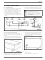
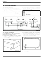
4.5 Securing the unit to the wall
4.5.1 Deciding the position
B If being used in a public place, position the unit out of
reach to discourage vandalism.
B Mount the unit onto a flat section of wall, well away
from any potential splashes of water or spray.
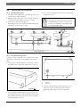
B Position the unit as shown (Fig. 4).
Remember to keep the length of hot water pipe to a
minimum in order to save energy.
B If the unit is to supply a sink, you can It it either above
or below the sink.
Fig. 4 Examples of installations
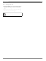
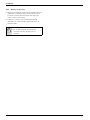
4.5.2 Deciding the wiring route
You have a choice of whether to feed the electric cable
through the cover bottom or through the back of the
unit,
B If it is going to be through the cover bottom, cut out
the plastic lug to expose the rubber sleeve (Fig. 5):
Fig. 5 Unit cover
B If it is going through the back of the cover unit, cut
through the grommet on the backplate with a sharp
knife. Make sure that you do not remove the grommet
from the backplate (Fig. 6):
Fig. 6 Back of unit
1 Grommet
2 Fixing holes
B Feed the cable through the grommet before you
mount the unit to the wall. If you are using an
approved cable fitting, remove the grommet.
WARNING:
B Unit must be mounted as shown in Fig. 4
with plumbing connection on the bottom.
Under no circumstances should the unit
be mounted differently.
Cold
Hot
Cold
Hot
Cold
Hot
Show front view
1
2
6720646914-07.1V

12 | Installation US
6 720 647 088 (2011/09)
4.5.3 Mounting on the wall
B Undo the retaining screws on the cover and take the
cover of the unit. Hold the backplate in position
against the wall while you mark the four mounting
holes.
B Drill the holes and secure the unit to the wall using
the four no. 8 wood screws supplied.
WARNING:
B Do not install a non-return check valve
within 6 feet of the inlet.

Starting up the Tronic 3000C Pro | 13US
6 720 647 088 (2011/09)
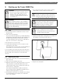
5 Starting up the Tronic 3000C Pro
5.1 Sink
B Check that the power is switched on at the circuit
breaker panel.
B Turn on the hot tap FULLY.
If you do not turn the tap full on, you will find that the
temperature of the water may vary. The hot water can
be adjusted by altering the temperature dial and
correctly setting the flow rate. Refer to appendix on
page 14 - correct flow vs. temperature.
If the unit has been used recently:
B run the water through for a few seconds to let the
temperature settle down.
If the unit has been used recently, You may initially get
a short burst of very hot water from the unit.
If a second tap connected to the unit is also turned on,
the hot water will be shared between the two, therefore
the flow and/or the temperature of the water will
decrease.
5.2 Adjusting the flow
B Ensure the service valves are open and check that no
pipe joints leak.
B Turn on the hot tap fully at the sink.
B Adjust the outlet service valve till the water comes out
of the tap at the recommended flow rate for the
required temperature. Refer to Appendix on page 14:
Correct flow vs. Temperature.
If the required temperature is different from the
factory setting, turn the Adjustment Spindle (Fig. 7)
until the outlet temperature is correct.
B Check that the unit works correctly when the sink tap
is closed and then opened again; if not adjust the
service valve slightly.
B The outlet shut off valve can be used to regulate
temperature or flow of water from the unit.
B Remove nameplate in direction of Arrow A (Fig. 7).
B Adjust the temperature setting using a screwdriver on
the spindle as shown by arrow B (Fig. 7).
Fig. 7 Temperature adjustment spindle
B Replace the nameplate.
WARNING:
B Do not use the unit if you think it may be
frozen, as this could result in serious
damage to the unit. Wait until you are
sure it has completely thawed out before
you switch it on.
WARNING:
Before turning on power, open cold water
shutoff valve to the unit and turn on all hot
water taps supplied by the unit. Flow water
out the tap(s) until all air has purged from
the unit and plumbing.
When using the hot water at a fixture, open
tap fully. To regulate hot water temperature,
adjust the temperature dial and flow rate as
recommended in the Appendix on page 10.
NOTE:
If the unit is servicing a single lever faucet
you may need to restrict the cold water
supply to the faucet to balance water
pressure and improve performance.
NOTE:
B Before leaving the site, the installer
should demonstrate the unit to the user
and give him/her this guide.

14 | Starting up the Tronic 3000C Pro US
6 720 647 088 (2011/09)
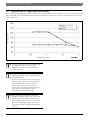
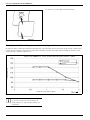
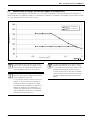
5.3 Appendix Flow vs. Temperature Setting Guide
The following graph Indicates the water temperatures the Thermostatic Tronic 3000C Pro can achieve at different flow
rates. The graph shows the maximum and minimum temperatures achievable for the 12 kW unit with an inlet water
temperature of 50°.
Fig. 8
Flow Rate (US gpm)
Temperature (ºF)
12kW Tronic 3000C Pro - US12 (Incoming water temperature = 50ºF)
Maximum temperature
Minimum Temperature
setting
Setting
As water temperature varies throughout the
year adjustments to the Temperature
Adjustment Spindle and/or the flow rate
may be required.
We recommend setting the temperature
adjustment spindle to the maximum setting.
(see graph above).
If necessary, adjust the outlet service valve
until the water comes out of the tap at the
desired temperature (increase flow for
cooler water, decrease flow for hotter
water). The heater will then maintain the set
temperature in the summer months
reducing the power automatically.
When inlet water temperature increases
during the summer months, the heater will
maintain set temperature by reducing the
power automatically. In cases of extremely
warm incoming water supply, open service
valves fully to ensure maximum flow through
the unit.

Troubleshooting | 15US
6 720 647 088 (2011/09)
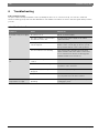
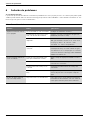
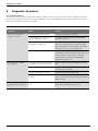
6 Troubleshooting
If the problem persists:
The person who initially installed the unit is probably the best one to contact for help. You can also call Bosch
Thermotechnology Corporation at 800-798-8161 or visit www.bosch-climate.us. Please have this guide with you when
you call.
6.1 For the Installer
Symptom Cause What do do
Cold water only -neon light
off.
Electricity not on. Check electrical supply.
The water supply is connected to
the OUTLET of the unit.
Reconnect the water supply to the INLET
(marked in blue).
The high temperature thermal cut
out has tripped.
Reset it by opening the unit and pushing the
button on the cut out (Fig. 2). Before you do
this you must find the cause of the problem.
The flow switch is not working. Turn off the power and observe if the flow
switch activates when the water is turned on.
If not contact Bosch Thermotechnology 800-
798-8161 www.bosch-climate.us
Water too cold -neon light
on.
Water flow too high for unit to
control
Adjust water flow to recommended flow rate.
One element is not working. Switch off the electricity and check the
resistance of the elements.
The power supply voltage has
dropped.
Check the supply voltage to the heater.
Temperature is turned too low.
Ensure that the temperature dial is in the
correct position for the flow of water.
Water flow too low, or
temperature too high.
There are restrictions in the
plumbing.
Check the plumbing. Only use Teflon tape for
sealing pipe joints.
Table 6

16 | Troubleshooting US
6 720 647 088 (2011/09)
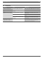
6.2 For the User
Symptom Cause What do do
Little or no water flows. The water supply is turned off. Turn on the main supply fully at the stop valve.
Cold water only -neon light
off.
The flow is not high enough to
activate.
Open the inlet service valve fully.
Cold water only -neon light
on.
The water flow rate is too high. Adjust the flow rate with hot water outlet
service valve.
The flow rate is correct. Adjust the temperature dial on the front of the
cover.
The inlet water temperature has
dropped.
Adjust the flow rate with hot water outlet
service valve.
Water flow rate too low, or
temperature too high.
The hot tap is not fully open Adjust the stop/ball valve so that water is at the
right temperature with the tap fully open.
Always turn the hot tap fully on.
Table 7

Interior components and parts list | 17US
6 720 647 088 (2011/09)
7 Interior components and parts list
Fig. 9
For further information ask your local dealer.
FOR SERVICE AND INSTALLATION QUESTIONS CALL:
Tel: 800-798-8161
Fax: 603-965-7581
Bosch Thermotechnology Corporation
Bosch Thermotechnology Corp.
50 Wentworth Avenue
Londonderry, NH 03053
Phone 800-798-8161
Fax 603-965-7581
www.bosch-climate.us
6720646914-09.1V
Outlet
Inlet
Number Code Comp. description
3 8-738-700-872-0 12 kW Printed Circuit Board (Thermostatic)
5 8-738-700-869-0 Terminal Block
8 8-738-701-695-0 Cable Clamps & Rubber Boot
11 8-738-700-870-0 Thermal Cut-out
12 8-738-700-862-0 Cover Retaining Screws
--- 8-738-701-710-0 Front Cover (not shown)
Table 8

18 | Tabla de contenidos US
6 720 647 088 (2011/09)
Tabla de contenidos
1 Explicación de los símbolos e instrucciones
importantes de seguridad . . . . . . . . . . . . . . . . . 19
1.1 Explicación de los símbolos . . . . . . . . . . . 19
1.2 Instrucciones Importantes de Seguridad . 19
2 Información sobre el calentador . . . . . . . . . . . . 20
2.1 Exención de responsabilidad . . . . . . . . . . 20
2.1.1 Número de aprobación . . . . . . . . . . . . . . . 20
2.2 Identificación del código técnico . . . . . . . 20
2.3 Identificación de nombre y número de
modelo . . . . . . . . . . . . . . . . . . . . . . . . . . . 20
2.4 Contenido del paquete . . . . . . . . . . . . . . . 20
2.5 Descripción general . . . . . . . . . . . . . . . . . 21
2.6 Función . . . . . . . . . . . . . . . . . . . . . . . . . . . 22
3 Reglamentos . . . . . . . . . . . . . . . . . . . . . . . . . . . . 23
4 Instalación . . . . . . . . . . . . . . . . . . . . . . . . . . . . . 24
4.1 Información importante . . . . . . . . . . . . . . 24
4.1.1 Prevención de congelamiento . . . . . . . . . . 24
4.2 Instalación del Tronic 3000C Pro . . . . . . . 24
4.3 Conexiones de agua . . . . . . . . . . . . . . . . . 25
4.3.1 Calidad del agua . . . . . . . . . . . . . . . . . . . . 25
4.4 Conexiones eléctricas . . . . . . . . . . . . . . . . 26
4.5 Asegurar la unidad a la pared . . . . . . . . . . 27
4.5.1 Decidir la posición . . . . . . . . . . . . . . . . . . 27
4.5.2 Decisión de la ruta del cableado . . . . . . . 27
4.5.3 Montaje en la pared . . . . . . . . . . . . . . . . . 28
5 Puesta en marcha del Tronic 3000C Pro . . . . . . 29
5.1 Fregadero . . . . . . . . . . . . . . . . . . . . . . . . . 29
5.2 Ajuste del flujo . . . . . . . . . . . . . . . . . . . . . 29
5.3 Apéndice Flujo vs Temperatura Guía de
Configuración . . . . . . . . . . . . . . . . . . . . . 30
6 Solución de problemas . . . . . . . . . . . . . . . . . . . . 32
6.1 Para el Instalador . . . . . . . . . . . . . . . . . . . 32
6.2 Para el Usuario . . . . . . . . . . . . . . . . . . . . . 33
7 Componentes interiores y lista de piezas . . . . . 34

Explicación de los símbolos e instrucciones importantes de seguridad | 19US
6 720 647 088 (2011/09)
1 Explicación de los símbolos e instrucciones importantes de
seguridad
1.1 Explicación de los símbolos
Advertencias
Se utilizan palabras de precaución al inicio de una adver-
tencia para indicar el tipo y la gravedad del riesgo resul-
tante si no se aplican medidas para minimizar los daños.
• NOTA indica que se pueden producir daños menores
a la propiedad.
• PRECAUCIÓN indica posibles lesiones menores
personales a mediano plazo.
• ADVERTENCIA indica posibles lesiones personales
graves.
• PELIGRO indica que pueden ocurrir lesiones
personales graves.
Información importante
Símbolos adicionales
1.2 Instrucciones Importantes de
Seguridad
Al utilizar equipos eléctricos, se deben seguir la
precauciones básicas de seguridad, incluyendo las
siguientes:
B Lea y siga todas las instrucciones
B Este aparato debe estar conectado a tierra.
B Desconecte este producto del suministro eléctrico
antes de limpiarlo, darle servicio o quitar la cubierta.
B Para reducir el riesgo de lesiones, es necesaria una
estrecha supervisión cuando el producto se utiliza
cerca de niños o personas mayores.
B Advertencia: Instalación en interiores solamente,
donde no quede expuesto a la congelación.
B Advertencia: No instale una válvula de retención o
cualquier otro tipo de limitador de caudal de retorno
dentro de seis pies de la entrada de agua fría.
B La instalación eléctrica debe ser conforme a los
actuales Códigos Eléctricos Nacionales.
B Advertencia: No encienda el calentador si sospecha
que puede estar congelado. Espere hasta estar
seguro de que se funda completamente
descongelado.
B El Tronic 3000C Pro está diseñado para calentar agua
fría potable para uso doméstico. Contacte a Bosch
Thermotechnology antes de especificar o instalar el
aparato en cualquier otra aplicación.
Instrucciones adicionales canadienses de seguridad
• Una terminal verde (o conector con la marca "G",
"GR", "TIERRA", o "TIERRA") se proporciona dentro de
la caja de control. Para reducir el riesgo de descargas
eléctricas, conecte esta terminal o conector a la
terminal de tierra del servicio eléctrico del panel de
alimentación con un cable de cobre, de conformidad
con el Código Eléctrico Canadiense, Parte I.
• Este producto estará protegido por un interruptor
diferencial Class A.
Guarde estas instrucciones
B Guarde esta guía en un lugar seguro una vez que su
unidad Tronic 3000C Pro ha sido instalada.
B Es posible que tenga que referirse a ella para
consultar las instrucciones generales o de
mantenimiento futuro.
Las advertencias se indican en el texto me-
diante un triángulo de advertencia y un fon-
do gris.
En caso de peligro por descarga eléctrica, el
signo de exclamación en el triángulo de ad-
vertencia se sustituye por un símbolo de un
rayo.
Información importante que no presenta
ningún riesgo para las personas o los bienes
se indica con este símbolo. Está separado
por líneas horizontales arriba y abajo del
texto.
Símbolo Significado
B Secuencia de pasos
® Referencia cruzada a otros puntos de
este documento o de otros documentos
• Listado / entrada de la lista
– Listado / entrada de la lista (2º nivel)
Tab. 1

Información sobre el calentador
6 720 647 088 (2011/09)
20
2 Información sobre el calentador
2.1 Exención de responsabilidad
2.1.1 Número de aprobación
Estado de Massachusetts
Como condición para instalar este producto en el Estado
de Massachusetts se debe instalar una válvula de alivio
de presión en el lado del agua fría, por un plomero MGL
142 Sección 19. (Número de autorización: P1-09-25).
2.2 Identificación del código técnico
US Electrónica Instantánea
12 Máxima salida (kW)
M Control mecánico de temperatura
W Colgado a la pared
I Interior
H Instalación horizontal
B Conexiones de agua
2.3 Identificación de nombre y número de
modelo
2.4 Contenido del paquete
• Calentador de agua eléctrico
• 4 tornillos para madera Nº 8
US 12 M W I H B
Table 2
Nombre de modelo Número de modelo
Tronic 3000 C Pro US 12 M W I H B
Table 3
La page est en cours de chargement...
La page est en cours de chargement...
La page est en cours de chargement...
La page est en cours de chargement...
La page est en cours de chargement...
La page est en cours de chargement...
La page est en cours de chargement...
La page est en cours de chargement...
La page est en cours de chargement...
La page est en cours de chargement...
La page est en cours de chargement...
La page est en cours de chargement...
La page est en cours de chargement...
La page est en cours de chargement...
La page est en cours de chargement...
La page est en cours de chargement...
La page est en cours de chargement...
La page est en cours de chargement...
La page est en cours de chargement...
La page est en cours de chargement...
La page est en cours de chargement...
La page est en cours de chargement...
La page est en cours de chargement...
La page est en cours de chargement...
La page est en cours de chargement...
La page est en cours de chargement...
La page est en cours de chargement...
La page est en cours de chargement...
La page est en cours de chargement...
La page est en cours de chargement...
La page est en cours de chargement...
La page est en cours de chargement...
-
 1
1
-
 2
2
-
 3
3
-
 4
4
-
 5
5
-
 6
6
-
 7
7
-
 8
8
-
 9
9
-
 10
10
-
 11
11
-
 12
12
-
 13
13
-
 14
14
-
 15
15
-
 16
16
-
 17
17
-
 18
18
-
 19
19
-
 20
20
-
 21
21
-
 22
22
-
 23
23
-
 24
24
-
 25
25
-
 26
26
-
 27
27
-
 28
28
-
 29
29
-
 30
30
-
 31
31
-
 32
32
-
 33
33
-
 34
34
-
 35
35
-
 36
36
-
 37
37
-
 38
38
-
 39
39
-
 40
40
-
 41
41
-
 42
42
-
 43
43
-
 44
44
-
 45
45
-
 46
46
-
 47
47
-
 48
48
-
 49
49
-
 50
50
-
 51
51
-
 52
52


Bosch US12 Guide d'installation
- Catégorie
- Chauffe-eau
- Taper
- Guide d'installation
dans d''autres langues
- English: Bosch US12 Installation guide
- español: Bosch US12 Guía de instalación
