KitchenAid KUDE20FXSS2 Guide d'installation
- Catégorie
- Lave-vaisselle
- Taper
- Guide d'installation
Ce manuel convient également à

Kitch__id ®
iNSTALLATiONiNSTRUCTiONS
UNDERCOUNTER DISHWASHER
iNSTRUCTiONSD'INSTALLATION
LAVE-VAISSELLESOUS PLAN DE TRAVAIL
Table of Contents ................................... 2
Table des matieres .................................. 28
W10321585A

Table of Confenfs
Dishwasher Safety ................................. 2
Installation Requirements ........................... 3
Tools and Parts ................................... 3
Location Requirements ............................ 4
Drain Requirements ............................... 6
Water Supply Requirements ........................ 6
Electrical Requirements ............................ 6
Installation instructions ............................. 7
Prepare Cabinet Opening--Existing Utilities ........... 7
Prepare Cabinet Opening--New Utilities .............. 7
Prepare and Route Water Line ...................... 8
install Drain Hose ............................... 10
Install Moisture Barrier ........................... 11
Prepare Dishwasher ............................. 11
Make Power Supply Cord Connection ............... 12
Determine Cabinet Opening ....................... 13
installation instructions (cent,}
Install the Door Handle ........................... 14
Custom Panel Dimensions ........................ 14
Install Custom Panel ............................. 15
Choose Attachment Option ........................ 17
Move Dishwasher Into Cabinet Opening ............. 17
Connect to Water Supply ......................... 19
Connect to Drain ................................ 20
Make Direct Wire Electrical Connection .............. 20
Secure Dishwasher in Cabinet Opening ............. 22
Bottom Sound Pad installation ..................... 23
Complete installation ............................. 23
Check Operation ................................. 25
If Dishwasher Does Not Operate ................... 25
Additional Tips .................................. 25
DISHWASHER SAFETY
Your safety and the safety of others are very important.
We have provided many important safety messages in this manual and on your appliance. Always read and obey all safety
messages.
This is the safety alert symbol.
This symbol alerts you to potential hazards that can kill or hurt you and others.
All safety messages will follow the safety alert symbol and either the word "DANGER" or "WARNING."
These words mean:
You can be killed or seriously injured if you don't immediately
follow instructions.
You can be killed or seriously injured if you don't follow
instructions.
All safety messages will tell you what the potential hazard is, tell you how to reduce the chance of injury, and tell you what can
happen if the instructions are not followed.
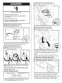
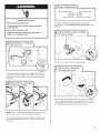
Tip Over Hazard
Do not use dishwasher until completely installed.
Do not push down on open door.
Doing so can result in serious injury or cuts.
You Need to:
, Slowly open dishwasher door while someone grasps the
rear of the dishwasher. Remove shipping materials, drain
hose and lower rack. Close dishwasher door until latched.
, Observe all governing codes and ordinances.
, Install this dishwasher as specified in these instructions.
, Installation should be performed by a qualified service
technician. The dishwasher must be installed to meet all
electrical and plumbing national and local codes and
ordinances.
2

iNSTALLATiON REQUIREMENTS
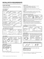
Tools and Parts
Gather the recommended tools and parts before starting
installation. Read and follow the instructions provided with
any tools listed here.
All Installations
Tools needed:
_,. _ z_..--_ Flat-blade
r,,ers I screwdriver
5 1
_e and ¼ _,,_ UL L sted/CSA
nut drivers or _Jf Approved twist-on _
hex sockets _ wire connectors* v
10" adjustable wrench_ %" chert-end
that opens to _f_'-_' wrench _f-_-_'_
1 "
1V_ (2.9 cm) _.
If installing custom front panels, ..._-J
Torx ®tT15 screwdriver
-Must be the proper size to connect _'our household wiring
to 16-gauge wiring in dishwasher
Other useful items you may need:
F ash ight _ Batht0we _
Parts supplied:
Drain hose Drain hose #10 x 1/2"
(lalampS(a2)nd ,_ Pehia_ps-
lsma _ _ screws (2)
2 - under-
counter
mounting
brackets (top)
Parts needed:
3 " 3 " " "
Comprx 3A hosefittLng
For part or k!t, see local
retailer or call Whirlpool
Parts: 1-800_442'9991. Part
Number WI0273460
4 #10 x 1/2"wood screws (if installing custom front panels)
Supplied in Kit:
4 Plastic studs (attached to each other by runners)
4 Short screws (10-16 hex head screw)
4 Long screws (8-18 Torx ®thead screws)
1 Template (located inside Use and Care Guide bag
assembly)
1 Instruction sheet (located inside Use and Care Guide bag
assembly)
NOTE: The screws supplied are used for only 3/4"thick
wooden panel. If the wooden panel is less than 3/4"thick,
customer must purchase screws locally.
Other parts you may also need:
1V2 -2 Masking or Moisture
(3.81-5 cm)duct tape barrier tape J_,_
screw4ype i i (Part Number/_/
clamps(3 maximum)[ ] 4396277)i
NOTE: Moisture barrier tape is recommended when installing a
dishwasher under a wood countertop.
NOTE: Parts available for purchase in plumbing supply stores.
Check local codes. Check existing electrical supply. See
"Electrical Requirements" section. It is recommended that
electrical connections be made by a licensed electrical installer.
In addition, for first=time installations
Tools needed:
Cordless drill
with 1/2";¾"
and 11/2'' hole
saw bits
Parts needed:
Copper tubing (%" see "Electrical Requirements,, SeCtion:
O.D.suggested)0r
flexible braided For Direct wire: For Pewer supply
Watersuauv ne use UL Listed/ Cord: useUL
CSA Approved Listed/CSA
_,,f'--_._,_\ I strain _elief Approved power
(.[.[._\_-_ _)_9.)))_ to fit% (2.2cm) supp!yCord kit
marked for uSeWith
dishWaSher
Additional parts supplied with top-venting models only:
2#8xlY8 TorX T15screwS 4#!0x y8 hex-head screws
Additional parts supplied with certain models only:
i B0tt0m sound pad
(located in lower rack) J
Make sure all these parts are included in the literature package.
If parts are not included, call 1-800-422-1230.
t® TORX is a registered trademark of Saturn Fasteners, Inc.
3

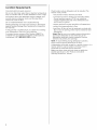
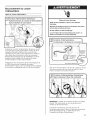
Location Requirements
Grounded electrical supply required.
Do not run drain lines, water lines or electrical wiring where
they can interfere with or contact dishwasher motor or legs.
The location where the dishwasher will be installed must
provide clearance between motor and flooring. Motor
should not touch the floor.
Do not install dishwasher over carpeted flooring.
Shelter dishwasher and water lines leading to dishwasher
against freezing. Damage from freezing is not covered by
the warranty.
A side panel kit is available from your dealer for installing
your dishwasher at the end of your cabinetry.
A moisture barrier accessory (Part Number 4396277) is
available from your dealer for installing underneath the
countertops. Call 1-800-422-1230 to order.
Check location where dishwasher will be installed. The
location must provide:
easy access to water, electricity and drain.
convenient access for loading and unloading dishes.
Corner locations require a 2" (5.1 cm) minimum
clearance between the side of the dishwasher door
and the wall or cabinet.
square opening for proper operation and appearance.
cabinet front perpendicular to floor.
level floor. (If floor at front of opening is not level with
floor at rear of opening, shims may be needed to level
dishwasher.)
Helpful Tip: Be sure to accurately measure dimensions
and ensure dishwasher is level if the floor in the
dishwasher opening is uneven (example: Flooring
extends only partway into opening).
NOTE: To avoid shifting during dishwasher operation,
shims must be securely attached to the floor.
If dishwasher will be left unused for a period of time or in a
location where it may be subject to freezing, have it
winterized by authorized service personnel.
Make sure pipes, wires and drain hose are within the
shaded area shown in the "Product and Cabinet
Opening Dimensions" section.
4

__;;;;;;_;_;;___;;;; ; _;;;;:____;;;;;_;;;;;;;;__ _;,__i __;_;;_ _;¸¸¸¸¸¸¸¸¸¸¸¸¸¸¸¸¸¸¸¸¸¸¸¸¸¸¸¸¸¸¸¸¸¸!¸¸__ ;;_;____ _,__;;;;;;;;;;____;_ __;;;;;;;;;;;;;;;;;;;;;;;;;;;;;;;;;;;;;_;;;;_ __ _; ___ _:______ ; _;___;;;;;;;;;;_;_;;;;;;;;__;;;;; ;_i __;__
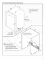
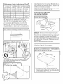
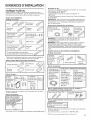
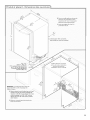
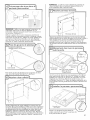
Product and Cabinet Opening Dimensions
31/_'' - 4W'
(8.8 cm -10.6 cm)
J
For 4" (10 cm) toe
kick, height of cabinet (9.,
opening is 341/2" (86.3 cm)
NOTE: Shaded areas of cabinet walls show where
utility connections may be installed.
D. Measured from the lowest point on the
underside of countertop. May be reduced
to 33%'" (86 cm) by removing wheels from
dishwasher, or 333/4'' (85.7 cm) by removing
wheels AND perforated section in the insulation
blanket.
E. Minimum, measured from narrowest point of opening.
B. For panel ready models, dishwasher
depth is 24" (60 cm) qot including the
_/4"(1.g cm) custom door panel
C. For Pro Line _ handle, depth is 28"
(70 cm).
A. Insulation may
be compressed.
(not used on all models)
p
Check that all surfaces
have no protrusions that would
prohibit dishwasher installation.

Drain Requirements
, A new drain hose is supplied with your dishwasher.
If drain hose is not long enough, use a new drain hose
with a maximum length of 12' (3.7 m) (Part Number
3385556) that meets all current AHAM/IAPMO test
standards, is resistant to heat and detergent, and fits the
1" (2.5 cm) drain connector of the dishwasher.
Make sure to connect drain hose to waste tee or disposer
inlet above drain trap in house plumbing and 20"
(50.8 cm) minimum above the floor. It is recommended
that the drain hose either be looped up and securely
fastened to the underside of the counter, or be connected
to an air gap.
Make sure to use an air gap if the drain hose is connected
to house plumbing lower than 20" (50.8 cm) above
subfloor or floor.
Use 1/2"minimum I.D. drain line fittings.
If required, the air gap, should be installed in accordance
with the air gap installation instructions. When you are
connecting the air gap, a rubber hose (not provided) will
be needed to connect to the waste tee or disposer inlet.
Water Supply Requiremenfs
A hot water line with 20 to 120 psi (138 to 862 kPa) water
pressure can be verified by a licensed plumber.
120°F (49°C) water at dishwasher.
3/8"O.D. copper tubing with compression fitting or
flexible braided water supply line (Part Number
4396897RP)
NOTE:1/2"minimum plastic tubing is not recommended.
A 90° elbow with 3/4"hose connection with rubber
washer
Do not solder within 6" (15.2 cm) of the water inlet valve.
Eiecfrical Requiremenfs
Be sure that the electrical connection and wire size are
adequate and in conformance with the National Electrical
Code, ANSI/NFPA 70 - latest edition and all local codes and
ordinances.
A copy of the above code standards can be obtained from:
National Fire Protection Association
1 Batterymarch Park
Quincy, MA 02269
You must have:
120-volt, 60 Hz, AC-only, 15- or 20-amp, fused electrical
supply.
Copper wire only.
We recommend:
A time-delay fuse or circuit breaker.
A separate circuit.
if connecting dishwasher
with a power supply cord:
. Use UL Listed power supply cord kit (Part Number
4317824) marked for use with dishwasher.
Power supply cord must plug into
a grounded 3 prong outlet, located in
the cabinet next to the dishwasher
opening. Outlet must meet all local
codes and ordinances.
if connecting dishwasher with direct wiring:
* Use flexible, armored
or nonmetallic
sheathed, copper wire
with grounding wire
that meets the wiring requirements for your home and
local codes and ordinances.
* Use a UL Listed!CSA Approved strain relief.

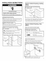
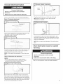
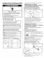
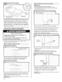
iNSTALLATiON iNSTRUCTiONS
Electrical Shock Hazard
Disconnect electrical power at the fuse box or circuit
breaker box before installing dishwasher.
Failure to do so can result in death or electrical shock.
D,_c0n_eCt electr'C a' power at the fuSe b0X oi Circu,t i
breaker b0x bef°re !nsta!!!ng dishwash
Yes _F011ow instructions in the "Prepa[e cabinet
Opening_Existing utilities,, section:
NO _FolloW instrUCti0nS inthe ,,Prepare Cabinet ....
Open!ng_New Ut!!it!es'! section:
E :isting g L ity hookups
Water line
Prepare Cabinet OpeningmExisfing
Utilities
If the water line and the cable extend to the locations
shown, proceed to the "Install Drain Hose" section. If they
do not reach far enough, follow the instructions in the
"Prepare Cabinet Opening--New Utilities" section.
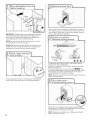
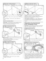
Prepare Cabinet OpeningmNew
Utilities
Prepare and route the electrical supply
What type of electrical
connection will you use? L
Direct Wire:
F011ow opti0n B inst[uctionS
Option A, Power Supply Cord:
NOTE: A grounded 3 prong outlet is required inside a
cabinet next to the dishwasher cabinet opening.
Drill a 11/2'' (3.8 cm) hole in cabinet side or rear.
See product and cabinet opening dimensions.
7

Woodcabinet:Sandtheholeuntilsmooth.
Metalcabinet:Coverholewithgrommetincludedwith
powersupplycordkit.
OptionB, Direct Wire:
Helpful Tip: Wiring the dishwasher will be easier if you
route the cable into the cabinet opening from the right-hand
side.
Drill a ¾" (1.9 cm) hole in right-hand cabinet side or rear.
See product and cabinet opening dimensions.
Wood cabinet: Sand the hole until smooth.
Metal cabinet: Cover hole with grommet (Part Number
302797 - not provided).
8
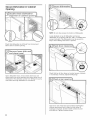
Route cable from power supply through cabinet hole (cable
must extend to the right front side of cabinet opening).
Tape cable to the floor in area shown. This will prohibit
cable from moving when dishwasher is moved into
cabinet opening.
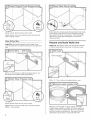
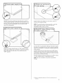
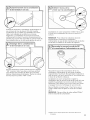
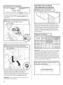
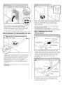
Prepare and Roule Waler Line
Helpful Tip: Routing the water line through the left side
of cabinet opening will make water connection easier.
Drill hole
Preferred locations
j
i
Drill a V2"(1.3 cm) hole in the cabinet side or rear.
Measure overall length of copper tubing or flexible
braided water supply line. Attach to the hot water line
using a connection configuration that is in compliance
with local codes and ordinances. The water line to the
dishwasher should have a manual shutoff valve.

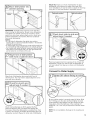
Slowlyroutewatersupplylinethroughholeincabinet.
(Ifusingcoppertubing,itwillbendandkinkeasily,sobe
gentle.)Itshouldbefarenoughintothecabinetopening
toconnectittothedishwasherinletonthefrontleft
sideofthedishwasher.
Slowlyturnwatershutoffvalveto "ON"position.Flush
waterintoashallowpanuntilcleartogetridofparticles
thatcouldclogtheinletvalve.Turnshutoffvalveto
"OFF"position.
Coppertubingonly:Slidenut,thenferrule,about1"
(2.5cm)ontocoppertubing.
NOTE:Toavoidvibrationduringoperation,routethe
watersupplylinesothatitdoesnottouchthe
dishwasherbase,frameormotor.
Connectthe3/8"compressionfittingtothewatersupply
linepriortoinstallingtheunitintothecabinetopening.
Attachsuchthatthe3/4"connectionisfacingupwardas
shownabove.
Coppertubingonly:Putthetubingintothe90°elbow
fittingasfarasitwillgo(thecoppertubingbendsand
kinkseasily).Slidethenutandferruleforwardandstart
thenutontotheelbowthreads.
Flexiblebraidedconnection:Securenuttoelbowusing
%"openendedwrenchoradjustablewrench.
NOTE:DonotuseTeflon®ttapewithcompression
fittings.
t® Teflon is a registered trademark of E.I. Du Pont de Nemours and
Company,
9

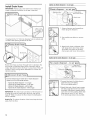
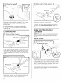
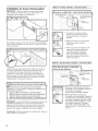
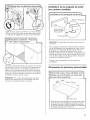
InsfallDrain Hose
IMPORTANT: Always use a new drain hose. Check local
codes to determine whether an air gap is required.
If needed, drill a 11/2"(3.8 cm) diameter hole in cabinet wall
or side of the opening closest to the sink.
Route drain hose as shown through hole in cabinet to the
front center of opening where drain connection will be
made. Tape drain hose to the floor in area shown. This will
prohibit it from moving when dishwasher is moved into
cabinet opening.
31Connect drain hose
Con nect d raJn hoSe tO waste tee or Waste disposer
using one of the following options:
option A, Waste disposer _ no air gap
, opti0n B,NO Waste dispOser _no air gap
option C, Waste disposer Jwith air gap
OPtion D, No waste disposer _with air gap
IMPORTANT: The drain hose connection of the disposer or
a waste tee must be made before the drain trap and at
least 20" (50.8 cm) above the floor where the dishwasher
will be installed.
Helpful Tip: To reduce vibration of the hose, keep the hose
away from the floor.
Option A, Waste disposer - no air gap
1. Using a hammer and screwdriver,
knock plug into disposer.
2. Use needle-nose pliers to remove
plug.
3. Attach drain hose to disposer inlet
with large silver drain hose clamp
(provided). Use pliers to squeeze
clamp open and move into position.
Option B, No waste disposer - no air gap
1. Connect black end of of drain hose to
waste tee and cut if needed.
(Do not cut ribbed section.)
2. Attach black end of drain hose to waste
tee with a large silver drain hose clamp
(provided). Use pliers to squeeze clamp
open and move into position. If the drain
hose was cut, use a 1W' to 2" (3.8 to
5 cm) screw-type clamp (not provided).
10

Option C, Waste disposer - with air gap
Drain trap
1. Using a hammer and screwdriver,
knock plug into disposer.
2. Use needle-nose pliers to remove
plug.
3. Connect black end of drain hose to air
gap and cut if needed. (Do not cut
ribbed section.)
4.
Attach drain hose to air gap with large
silver drain hose clamp (provided).
Use pliers to squeeze clamp open and
move into position. If the drain hose
was cut, use a 11/2'' to 2" (3.8 to
5 cm) screw-type clamp (not
provided).
5. Use a rubber hose (not provided) with
screw-type clamps (not provided) to
connect from air gap to disposer inlet.
Option D, No waste disposer - with air gap
2.
3.
Connect black end of drain hose to air
gap and cut if needed. (Do not cut
ribbed section.)
Attach drain hose to air gap with large
silver drain hose clamp (provided).
Use pliers to squeeze clamp open and
move into position. If the drain hose
was cut, use a 11A'' to 2" (3.8 to 5 cm)
screw-type clamp (not provided).
Use a rubber hose (not provided) with
screw-type clamps (not provided) to
connect from waste tee to air gap,
_i_if_i_if_i_ii_i_ii_i_ii_i_ii_i_ii_i_ii_i_iii_i_i_i_i_iiiii_1iiiiii1_1%iiiiiiiiiiiiii_iii;i;ii_i_i:iii;iiti;iit;iiii_i_;ii_i_;i_;;i_`ii`_`i_`ii`_`i_`ii`_`i_`ii`_`i_`ii`_`i_`ii`_`i_`ii`_`i_`ii`_`i_`ii`_`i_`i_:ii,i;_:ii,i;_:ii,ii,;,;,i;,iiiiii;ii'ii_ii_;i¸il_ii_ii_;i¸il_iii_;;iiii,',i_ii;i;'ii¸;i;'ii¸;i;'ii¸;i;'ii¸;i;___1_
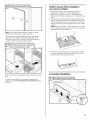
InstallMoisture Barrier
(undera wood countertop)
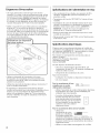
1. Make sure the area under the cabinet is clean and dry
for installation of the moisture barrier.
2. Remove the backing of the moisture barrier and apply
to underside of the countertop along the front edge of
the counter.
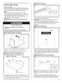
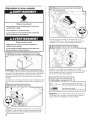
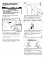
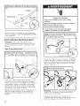
Prepare Dishwasher
Tip Over Hazard
Do not use dishwasher until completely installed.
Do not push down on open door.
Doing so can result in serious injury or cuts.
Excessive Weight Hazard
Use two or more people to move and install
dishwasher.
Failure to do so can result in back or other injury.
Put dishwasher on its __
11

Helpful Tip: Place cardboard under dishwasher until installed
in cabinet opening to avoid damaging floor covering. Do not
use door panel as a worktable without first covering with a
towel to avoid scratching the door panel.
Using two or more people, grasp sides of dishwasher door
frame and place dishwasher on its back.
Using a 1/4"hex head socket, nut driver or Phillips
screwdriver, remove 2 screws attaching access panel and
lower panel to dishwasher. Do not remove tech sheet
from access panel.
Using a 1/4"hex head socket, nut driver or Phillips
screwdriver, remove terminal box cover. Retain for
later use.
Install a UL Listed/CSA Approved strain relief. Make sure
screwheads are facing to the left when tightening conduit
nut. Strain relief is provided with the power supply cord kit.
12
NOTE: If using Option B, proceed to "Determine Cabinet
Opening," to continue with the installation of your
dishwasher.
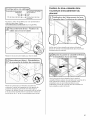
Make Power Supply Cord Connecfion
Option A, Power Supply Cord:
Route cord so that it does not touch dishwasher motor to
lower part of dishwasher tub. Pull cord through strain
relief in terminal bow. Take notice when installing or
removing the dishwasher in order to reduce the chance of
damaging the power supply cord.
Select UL Listed/CSA Approved twist-on wire connectors
(included with power supply cord kit) rated to connect your
power supply cord to 16-gauge dishwasher wiring.

ElectricalShock Hazard
Electrically ground dishwasher.
Connect ground wire to green ground connector
in terminal box.
Do not use an extension cord.
Failure to follow these instructions can result in
death, fire, or electrical shock.
--" Connect ground wire |
--_.
Remove the green grounding screw and place
through the ring terminal of the green ground wire.
Reattach and tighten the green screw.
NOTE: Twist on wire connector. Gently tug on wires to be
sure both are secured.
Connect wires black to black and white to white, using UL
Listed!CSA Approved twist-on wire connectors (included
with power supply cord kit).
P0wei Supp!y wire: Terminal box Wire:
.... white _ white I
black _ b!ack i
g[ound w!re _ ground connector
If needed, see website for animated representation of this
step. Visit www.kitchenaid.eom under FAQ tab.
Tighten strain relief screws to secure cord.
0
Place wires inside terminal box. Insert tabs
on left side of cover. Make sure wires are tucked inside
box. Close cover ensuring wires are not pinched. Use 1/4"
nut driver and previously removed screw to secure
cover.
NOTE: Do not plug into outlet until instructed to do so.
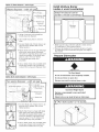
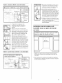
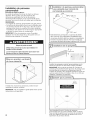
Defermine Cabinef Opening
Measure height of cabinet opening from underside of
countertop to floor where dishwasher will be installed
(you will need to measure the lowest point on the
underside of the countertop and the highest point on the
floor). Refer to "Dishwasher Height Adjustment Chart"
for wheel position and the number of turns needed.
13

Dishwasher Height Adjustment Cha
Minimum, Wheel Number of turns ' Perforation
cutout height position on front leg on blanket
33si4,,(85:7cm) ' remove ' all the way up I remove:
I ! I
337A" (86 cm)remove all the way up keep
341/2,(87i6Ore)
NOTE: If the mimmum cabinet opening height is less than
34" (86.4 cm), the rear wheels can be removed for
additional clearance. This will allow the dishwasher to fit
into a 337/8.' (86 cm) high cabinet opening, but the
dishwasher will be more difficult to move. (Measurements
are approximate. Wheels and legs are preset at the
factory for 341/2.' [87.6 cm].) If the minimum cabinet
opening height is 33s/4" (85.7 cm), a section in the
insulation blanket can be removed by cutting along the
perforation.
Adjust wheels and legs
Turn both leveler legs to the same height. Put wheels in
the required position determined from "Dishwasher
Height Adjustment Chart."
Built-up floors: If the kitchen floor is higher than the
cabinet opening's floor - for example, the kitchen floor tile
does not extend into the cabinet opening - add shims as
needed in the area shown to bring the dishwasher up to
34" (86.4 cm) below the countertop.
NOTE: Shims must be securely attached to floor to avoid
movement when the dishwasher is in use.
iii iiii!iiiiiiiiiiiiiiiiiiiii_iiiii....................................................................................................................................................................................................................................................................................................................................................i_
Insfall the Door Handle
(on some models)
Mounting stud
Handle
Setscrew
(in bottom
of handle)
Hex key
IMPORTANT: Do not scratch the front panel during this
procedure.
Remove the door handle and hardware bag containing the
setscrews and hex key from the cardboard box. Setscrews
are already installed in the handle. Place handle on
mounting studs with the setscrews facing down. Push the
door handle tightly against the door. Insert the short end
of the hex key into the setscrews. Tighten the setscrews 1/4
turn past snug.
Retain hex key with Installation Instructions.
Cusfom Panel Dimensions
'gSto '¸';ons D;shwas
with control panel on the top
23%" --'_ _'-_
(60 cm) *292%2'' (76 cm)
*This dimension is for 4" (10.2 cm) toe kick. If the
installation needs a higher toe kick, adjust the height
of the wood panel accordingly. Not recommended for
toe kicks greater than 6" (15.2 cm). ,,
14

InstallCustom Panel
Follow steps below:
A customer supplied panel must weigh no more than
16 Ibs (7.3 kg) and must be made to specific dimensions.
It is recommended that a cabinetmaker cut the customer
panel because of the precise dimensions needed.
NOTES:
The handle for the custom panel is not included.
All mounting hardware supplied is for a 3/4"(19.1 cm)
thick wood panel. If a thinner wood panel or materials
other than wood are used, it is the customer's
responsibility to obtain the proper length screws and
adjust the pilot holes accordingly.
iMPORTANT: Use a moisture resistant sealer on both
sides and all edges of the panel to avoid damage from
moisture.
Excessive Weight Hazard
Use two or more people to move and install
dishwasher.
Failure to do so can result in back or other injury.
Using 2 or more people, stand the dishwasher up.
NOTE: Do not install kickplate until instructed to do so.
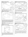
l_Custom panel installatio
"-:J Dishwashers with control /
panel on the top |:
/
23%" /_
(60 cm) I *292%2" (76 cm)
3/4"(19.1 mm)
*This dimension is for 4" (10.2 cm) toe kick. If the
installation needs a higher toe kick, adjust the height
of the wood panel accordingly. Not recommended for
toe kicks greater than 6" (15.2 cm).
Attach handle
Install the custom hardware handle(s) on the front of the
wooden panel inside dotted line.
iMPORTANT: If the handle is attached from the back of
the custom panel, the screw holes should be
countersunk for the screws heads to be flush with the
panel. If the handle is attached to the front of the custom
panel, the screw lengths cannot exceed the panel
thickness.
i T°P Of Panel
Tapa del panel
Dessu_ de panneau
Cent_rline
Pilot!ole_
Using the template provided attached it to the backside
of the custom panel with tape. Make sure that the center
of the template is aligned with the center of the wooden
panel and top of the template is aligned to the top face
of the wooden panel.
NOTE: Do not drill deeper then %" to keep from drilling
through panel. Pilot hole depths given are for 3/4"thick
panel.
Mark 4 pilot holes on the wooden panel using the
template provided. Predrill 4 pilot holes using a 3/32"drill
bit. Use tape to mark the drill bit to gauge hole depth.
Drill pilot holes approximately %" into the custom panel.
15

Visibleside
Attachthe4plasticstudstothewoodenpane
usingthe4shorthexhead(sAc")screws_ "
Attach custom tape
Check custom tape alignment with metal door slots; verify
tape is right-side up, and that the tape does not overhang the
metal door on the top, bottom or side interfaces. Remove the
backing from the custom tape by pulling straight down on
the liner. Align the custom tape to the keyhole slots on the
metal door (see image) and apply. Repeat steps for one side
and then the other.
NOTE: The adhesive on the tape is aggressive, so proper
alignment and attachment to the metal door needs to occur
on the first try.
Wooden panel
assembly
Align the studs on the custom wood panel to the keyhole
slots on the door assembly. Ensure that all 4 plastic studs are
engaged in the keyhole slots. Slide wood panel down until
the top surface of the wooden panel is flush with the top of
the door.
16
Customer-supplied
panel
Drill through
these holes.
Remove 2 short screws
and replace with long
screws provided.
Open the door and align top edges. Predrill 2 pilot holes
using a 3/32"drill bit. Use tape to mark the drill bit to gauge
hole depth. Drill pilot holes approximately 11/2.' (12.7 mm)
into the top corners of the door using hole in liner as a
guide.
Install custom panel'S: .......................................................
top
edges
gh
these holes
Customer-supplied
panel
Install 2 long screws supplied in top corners to secure
custom wood panel in place,
Remove the short screws
edges
Remove 2short Customer-supplied
and replace with long panel
screws provided.
Remove the short screws (3rd from top) on either side of
the inner door panel. Predrill 2 pilot holes using a 3/32"drill
bit. Use tape to mark the drill bit to gauge the hole depth.
Drill pilot holes approximately 11/2.' using the door liner
hole as a guide into the panel. Install the 2 remaining long
screws.

Choose Attachment Option
Excessive Weight Hazard
Use two or more people to move and install
dishwasher.
Failure to do so can result in back or other injury.
Use 2 or more people to move and install dishwasher.
Option 1, Countertop attachment:
Tabsmust point
_= _/tothe right
Remove the brackets from the package and place in the
open slots on the left and right-hand top of the
dishwasher collar as shown.
Insert the bracket into the slot on the collar. Using a pair
of pliers, bend the tab down to secure the bracket in
place. Repeat this step for the other side.
NOTE: Do not attach the dishwasher. This will be done
later.
Option 2, Dishwasher side attachment:
NOTES:
Remove the brackets from the parts package.
You must predrill pilot holes in cabinet to avoid
splitting the wood before installing screws.
Break off the end of the bracket along the scored line.
With another person holding the rear of the dishwasher
to keep it from tipping, open dishwasher door and place
towel over pump assembly and spray arm of dishwasher.
This will keep screws from falling into pump area when
you are securing dishwasher to cabinet.
Push the plastic buttons out of the side of the tub.
NOTE: Save the buttons to cover the holes after
dishwasher is installed.
Push bracket into slot on the side of dishwasher, and
bend tab in toward the side of the dishwasher so that it
keeps the bracket in place. Repeat this step for the other
side of the dishwasher.
NOTE: Do not attach the dishwasher. This will be done
later.
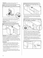
Move Dishwasher Close to Cabinet
Opening
Excessive Weight Hazard
Use two or more people to move and install
dishwasher.
Failure to do so can result in back or other injury.
Use 2 or more people to move and install dishwasher.
17

IMPORTANT: Double-check correct placement of utilities.
Grasp the sides of the dishwasher at the edges of the
door panel. Tilt dishwasher backward on wheels and
move dishwasher close to cabinet opening.
NOTE: Do not push on the front of the panel or on the
console. Panel or console may dent.
Helpful "lip: Temporarily tape utilities to the floor in the
locations shown to prohibit them from moving when
dishwasher is moved into the cabinet opening.
Check that water line is on the left side of opening and
drain hose is near the center of the cabinet opening.
18
With another person holding the dishwasher to keep it
from tipping, open and close the door a few times. If the
door closes or falls open under its own weight, the door
tension will need to be adjusted.
Screw [] []
To adjust the door spring tension, unhook the spring
from the rear leg of dishwasher.
Using a sA6"nut driver or hex socket, remove the screw
from the tensioner.
The screw can be put into one of 3 holes I[ll, m, ll_ in the
front leg of dishwasher. If the door closes by itself, move
the tensioner to a lower-numbered hole and replace
screw. Reattach door spring to rear leg.
NOTE: Tensioners on both sides of dishwasher should be
secured at same holes.
--" Increase spring tension
When door is unlatched, if door opens by itself, move
the tensioner to a higher-numbered hole and replace the
screw. Reattach door spring to rear leg.
NOTE: Tensioners on both sides of dishwasher should
be secured at same holes.

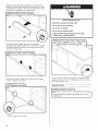
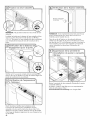
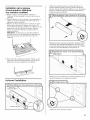
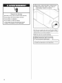
Move dishwasher int
-'-' cabinet opening .................................................
Insulation
iMPORTANT: If wheels were removed, cover the floor
when moving the dishwasher. Slowly move dishwasher
completely into cabinet opening. Do not kink or pinch
water line, drain hose, power supply cord or direct wire
between dishwasher and cabinet. Remove cardboard
from under dishwasher.
NOTES:
* It is all right if dishwasher fits tightly into cabinet
opening. Do not remove insulation blanket- the blanket
reduces the sound level.
* If using power cord, make sure to route end through hole
in cutout before sliding dishwasher into cabinet opening.
* For models with water softener, make sure that the drain
hose stays on the hanger that is on the right-hand side
and is tucked in on the side of the unit.
Align front of dishwasher door panel with front of
cabinet doors. You may need to adjust alignment to be
even with your cabinets.
Check that leveling legs are firmly against the floor.
Close and latch the door, and place level against the
front panel. Check that dishwasher is centered from front
to back in the opening. If needed, adjust leveling leg until
dishwasher is plumb. Repeat for other side of dishwasher.
Helpful Tip: Push up on front of dishwasher to raise
dishwasher offthe ground to adjust front legs. With
some installations, it may be easier to adjust the front leg
using the sA6"hex head socket or adjustable wrench.
Place level against top front opening of tub. Check that
dishwasher is level from side-to-side. If dishwasher is
not level, adjust front legs up or down until dishwasher
is level.
Connect to Water Supply
Be sure rubber washer is properly seated in fitting. Slide
the 3/4"fitting up to the valve and hand tighten to avoid
cross-threading. Hand tighten until the coupling is tight.
Using pliers, check the tightness of the coupling. An
additional 1Ato 1/2turn may be required to seal the rubber
gasket.
NOTE: Do not overtighten. Damage to the coupling can
result.
19

\
6
Place paper towel under 90° elbow fitting. Turn on water
supply and check for leaks. If leak occurs, repeat
previous step.
If needed, see website for animated representation
of this step. Visit www.kitchenaid.corn/watersupply
under FAQ tab.
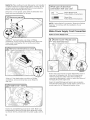
Black drain hose
Place towel under drain hose to catch any water in drain
hose. Place the small green drain hose clamp onto the
small end of the drain hose. Push the new drain hose
into the black drain hose connector up to the drain hose
stop.
Using pliers, squeeze open the small green drain hose
clamp and slide onto connector between stops.
Black drain hose
connector --
Green clamp
Drain hose
After hose is connected, remove towel.
If needed, see website for animated representation of
this step. Visit www.kitehenaid.eorn/drain under FAQ
tab.
Make DirectWire Electrical
Connection
NOTE: If the power supply cord was connected earlier,
proceed to "Secure Dishwasher in Cabinet Opening"
section.
Option B, Direct Wire:
Route cable so that it does not touch dishwasher motor
or lower part of dishwasher tub. Pull cable through UL
Listed!CSA Approved strain relief in terminal box. Strain
relief is not supplied with the dishwasher. Owner must
purchase a 7/8"screw-in type strain relief.
Select UL Listed/CSA Approved twist-on wire connectors
(not included) rated to connect your household wiring to
16-gauge dishwasher wiring.
20
La page est en cours de chargement...
La page est en cours de chargement...
La page est en cours de chargement...
La page est en cours de chargement...
La page est en cours de chargement...
La page est en cours de chargement...
La page est en cours de chargement...
La page est en cours de chargement...
La page est en cours de chargement...
La page est en cours de chargement...
La page est en cours de chargement...
La page est en cours de chargement...
La page est en cours de chargement...
La page est en cours de chargement...
La page est en cours de chargement...
La page est en cours de chargement...
La page est en cours de chargement...
La page est en cours de chargement...
La page est en cours de chargement...
La page est en cours de chargement...
La page est en cours de chargement...
La page est en cours de chargement...
La page est en cours de chargement...
La page est en cours de chargement...
La page est en cours de chargement...
La page est en cours de chargement...
La page est en cours de chargement...
La page est en cours de chargement...
La page est en cours de chargement...
La page est en cours de chargement...
La page est en cours de chargement...
La page est en cours de chargement...
-
 1
1
-
 2
2
-
 3
3
-
 4
4
-
 5
5
-
 6
6
-
 7
7
-
 8
8
-
 9
9
-
 10
10
-
 11
11
-
 12
12
-
 13
13
-
 14
14
-
 15
15
-
 16
16
-
 17
17
-
 18
18
-
 19
19
-
 20
20
-
 21
21
-
 22
22
-
 23
23
-
 24
24
-
 25
25
-
 26
26
-
 27
27
-
 28
28
-
 29
29
-
 30
30
-
 31
31
-
 32
32
-
 33
33
-
 34
34
-
 35
35
-
 36
36
-
 37
37
-
 38
38
-
 39
39
-
 40
40
-
 41
41
-
 42
42
-
 43
43
-
 44
44
-
 45
45
-
 46
46
-
 47
47
-
 48
48
-
 49
49
-
 50
50
-
 51
51
-
 52
52


KitchenAid KUDE20FXSS2 Guide d'installation
- Catégorie
- Lave-vaisselle
- Taper
- Guide d'installation
- Ce manuel convient également à