Zenner OD2 Manuel utilisateur
- Catégorie
- Antennes réseau
- Taper
- Manuel utilisateur

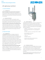
ill. 1
English
Installation and operating instructions
IoT gateway outdoor
1. General information
1.1. Intended use
Operational safety is only guaranteed if the product is
used as intended by the manufacturer. No liability is
assumed for damage caused by other applications. Any
modifications are only permitted with approval from the
manufacturer. Otherwise the manufacturer’s declaration
is invalidated.
1.2. Safety instructions
If it is necessary to establish a new power connec-
tion, the installation and commissioning must only be
performed by trained qualified specialists. Only trained
qualified electricians may work on electrical systems.
They must be able to assess the work assigned to them
at all times, detect any potential sources of danger and
adopt appropriate safety measures. The installation
work must only be performed in a de-energised state.
Valid specifications and standards are to be observed.
During assembly of the gateway, the applicable national
standards are to be observed on setting up antennae
systems.
2.2. Scope of delivery
The gateway is delivered in a partially assembled state.
Depending on the assembly situation to be imple-
mented, various preparations and assembly steps are
necessary. Furthermore, it may be necessary to acquire
additional assembly materials that are not included in
the scope of delivery.
Gateway - pre-mounted on mounting bracket
Mounting bracket with nuts, spring ring and
washers
2x spacer sleeves for mounting bracket 2x 868
MHz LoRaWAN®-Antennas
Network cable (5 m)
Cable ties
2x RJ45 connector
Equipotential bonding cable (16 mm²)
Power cord for PoE injector
■
■
2. Product description
■
2.1. Intended use
The ZENNER IoT Gateways use high-performance
LoRaWAN® technology, whose excellent building
penetration and long-range network coverage generally
ensure the connectivity of IoT sensors even under chal-
lenging environmental and installation conditions.
The Outdoor Gateway is ideally suited for LoRa network
coverage in rural and urban areas to receive values from
multiple sensors. The device can be used across various
sectors for a variety of IoT applications and is an integral
part of ZENNER IoT system solutions. With a few gate-
ways, entire cities can already be covered.
Due to the very robust housing made of coated alumi-
num, the Outdoor Gateway is very resilient to extreme
weather conditions and is characterized by a high
degree of reliability. In addition to the two external LoRa
antennas, the ZENNER IoT Gateway Outdoor also uses
an external LTE antenna to ensure the best possible con-
nection to the backend.
■
■
■
■
■
■
2.3. Installation location
In order to gain optimum LoRaWAN network coverage,
an installation location which is as high as possible is
recommended due to various technological advan-
tages. For example, if an attic is available with potential
installation space, this installation location should be
preferred.
After selecting the preferred installation location, you
should test the cellular network connection in this
location prior to attaching it.
7

3. Mounting preparation
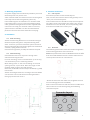
For power supply of the IoT Gateway Outdoor you need
the PoE Injector incl. power cord.
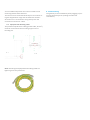
A 5m network cable incl. RJ45 connectors and PG gland
is already connected to the gateway (see ill. 6).
If the cable length is not sufficient or a network cable
is already present, you can cut the mounted network
cable, pull off the PG gland and use the supplied RJ45
connectors to crimp your network cable. In this case,
special tools are needed. It is also recommended to
perform a function test of the cable after crimping.
5.
Electrical connection
5.1.
PoE injector
Connect the power cord to the PoE Injecor.
Then connect the network cable of the gateway to the
"PoE" port of the PoE Injector.
If local network access should be used, the correspond-
ing cable is to be connected to the “Data” port. If local
network access is to be used, the corresponding cable
must be connected to the "Data" port.
4. Installation
4.1. Pole mounting
Attach the mounting bracket incl. mounted housing to
the desired pole using the u-shaped mounting hard-
ware. To do this, you must attach the spacer sleeves to
the mounting hardware and then tighten each side with
a washer, spring washer and nut.
Check that the gateway is stably attached to the pole.
ill. 4
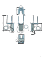
5.2. Antennas
The following illustration shows the usual arrangement
and mounting positions of the antennas.
Note:
The specifications of the LoRaWAN antennas differ
from the LTE broadband antenna. Please take care not
to mix up the antennas or connections!
4.2. Wall mounting
Check whether there are any lines running at the
selected mounting location.
For wall mounting, use the 4 slotted holes (2 at the top,
2 at the bottom) on the mounting bracket.
Mark drilling holes on the wall according to the hole
spacing and use a spirit level. Note the length of the
network cable (range to the PoE Injector).
Drill holes, fix dowels and screws (not included, e.g. M8)
in the holes.
Attach mounting bracket incl. housing to the wall. Make
sure that the correct side of the mounting bracket is
facing up. Please refer to ill. 3.
ill. 5
Attach the antennas and make sure to tighten the lock
nuts accordingly (wrench size SW19).
Now connect the antennas with the antenna cables and
the connectors on the housing using the following
connection layout.
115
10
60
8
115
197
ill. 2
ill. 3
ill. 6
8
Bracket Sets
8
See Note
:
5
the hole can be
used for grounding
286
311
Set U-steel rod
100
(
The total length of thread)
Connector Layout
LoRa 2
POE
LTE div.
LoRa 1 LTE main

You can additionally fasten the antenna cables to the
mounting bracket with cable ties.
The antennas are mounted identically for all variants us-
ing the supplied lock rings and serrated lock washers.
All antennas are connected to the gateway with the
enclosed N-connection cables.
6. Commissioning
The gateway starts immediately after plugging in/con-
necting the PoE Injector (making the electrical
connection).
5.3. Equipotential bonding cable
The potential equalization cable (ground cable, 16 mm²)
must be connected to the mounting support and a
bonding rail.
8
115
197
ill. 7
ill. 8
240
Note:
Attaching the Equipotential bonding cable to a
lightning rod is not permitted.
ill. 9
5
the hole can be
used for grounding
6
1
the hole can be
used for grounding
Gateway
component

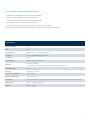
7. Technical data and performance characteristics
Suitable for LoRaWAN® IoT solutions from ZENNER
Bidirectional LoRaWAN® radio communication
Encrypted end-to-end data transmission (AES 128)
No storage of meter readings on the gateway
Plug & Play - Simple integration through pre-configured software
Security patches and software updates are distributed in an automated manner
■
■
■
■
■
■
Cellular network
n/a
# LoRa channel
16 channels - two external antennas
Frequency
US-902
external: 2 x LoRa
(antennas incl. mounting bracket included in scope
of delivery)
Antennas
Housing
Aluminium, coated
Storage temperature
- 40 °C to + 80 °C
Maintenance
Remote firmware upgrades
Weight
approx. 4.1 kg
10
Installation
Wall, pole (bracket incl. grounding cable included in scope of delivery, galvanized steel)
Operating temperature 0 °C to +50 °C
Protection class
IP67
Power supply
Power over Ethernet (PoE)
TX power max. 27 dBm (500 mW) conducted
LAN
RJ45
Technical data

19.8 cm
11.0 cm
15.2 cm
11
54.9
c
m
24.0
cm
31.2
c
m

8. Dismantling
Disconnect the gateway's power supply and uncouple
the network cable from the PoE Injector.
8.1. Pole mounting
Loosen the nuts of the mounting bracket. When doing
so, you should always hold the mounting bracket with
the housing. After completely loosening the nuts, you
can pull the gateway off the u shaped mounting bracket.
8.2. Wall mounting
First remove the bottom two screws between the
mounting bracket and the wall. Hold the mounting
bracket with the housing and slowly loosen and remove
the two upper bracket screws.
12

13
Federal Communication Commission Interference Statement
This equipment has been tested and found to comply with the limits for a Class B digital device, pursuant to Part 15 of the FCC
Rules. These limits are designed to provide reasonable protection against harmful interference in a residential installation. This
equipment generates, uses and can radiate radio frequency energy and, if not installed and used in accordance with the
instructions, may cause harmful interference to radio communications. However, there is no guarantee that interference will
not occur in a particular installation. If this equipment does cause harmful interference to radio or television reception, which
can be determined by turning the equipment off and on, the user is encouraged to try to correct the interference by one of the
following measures:
- Reorient or relocate the receiving antenna.
- Increase the separation between the equipment and receiver.
- Connect the equipment into an outlet on a circuit different from that to which the receiver is connected.
- Consult the dealer or an experienced radio/TV technician for help.
FCC Caution: Any changes or modifications not expressly approved by the party responsible for compliance could void the user's
authority to operate this equipment.
This device complies with Part 15 of the FCC Rules. Operation is subject to the following two conditions: (1) This device may not
cause harmful interference, and (2) this device must accept any interference received, including interference that may cause
undesired operation.
IMPORTANT NOTE:
Radiation Exposure Statement:
This equipment complies with FCC radiation exposure limits set forth for an uncontrolled environment. This equipment should
be installed and operated with minimum distance 20cm between the radiator & your body.
This transmitter must not be co-located or operating in conjunction with any other antenna or transmitter.
Country Code selection feature to be disabled for products marketed to the US/CANADA
Industry Canada statement:
This device contains licence-exempt transmitter(s)/receiver(s) that comply with Innovation, Science and Economic Development
Canada’s licence-exempt RSS(s). Operation is subject to the following two conditions:
(1) This device may not cause interference
(2) This device must accept any interference, including interference that may cause undesired operation of the device
L’émetteur/récepteur exempt de licence contenu dans le présent appareil est conforme aux CNR d’Innovation, Sciences et
Développement économique Canada applicables aux appareils radio exempts de licence. L’exploitation est autorisée aux deux
conditions suivantes :
(1) L’appareil ne doit pas produire de brouillage;
(2) L’appareil doit accepter tout brouillage radioélectrique subi, même si le brouillage est susceptible d’en compromettre le
fonctionnement.
This radio transmitter [IC: 26631-OD2] has been approved by Innovation, Science and Economic Development Canada to
operate with the antenna types listed below, with the maximum permissible gain indicated. Antenna types not included in this
list that have a gain greater than the maximum gain indicated for any type listed are strictly prohibited for use with this device.
Le présent émetteur radio [IC: 26631-OD2] a été approuvé par Innovation, Sciences et Développement économique Canada
pour fonctionner avec les types d'antenne énumérés ci-dessous et ayant un gain admissible maximal. Les types d'antenne non
inclus dans cette liste, et dont le gain est supérieur au gain maximal indiqué pour tout type figurant sur la liste, sont
strictement interdits pour l'exploitation de l'émetteur.
Type
Manufacture
Gain
Connector
Dipole
Auden
3.05
N type
Radiation Exposure Statement:
This equipment complies with Canada radiation exposure limits set forth for an uncontrolled environment. This equipment
should be installed and operated with minimum distance 20cm between the radiator & your body.
Déclaration d'exposition aux radiations:
Cet équipement est conforme Canada limites d'exposition aux radiations dans un environnement non contrôlé. Cet
équipement doit être installé et utilisé à distance minimum de 20cm entre le radiateur et votre corps.

14
S
u
b
j
e
c
t to t
e
c
hn
ica
l
mo
di
fi
ca
t
i
on
s
.
W
e
acc
e
p
t no
l
iabi
l
i
ty
f
o
r
a
ny
err
o
r
s
o
r
m
isp
r
i
nt
s
.
Professional installation instruction
Please be advised that due to the unique function supplied by this product, the device is intended for use with our interactive
entertainment software and licensed third-party only. The product will be distributed through controlled distribution channel
and installed by trained professional and will not be sold directly to the general public through retail store.
1. Installation personal
This product is designed for specific application and needs to be installed by a qualified personal who has RF and related
rule knowledge. The general user shall not attempt to install or change the setting.
2. Installation location
The product shall be installed at a location where the radiating antenna can be kept 20cm from nearby person in normal
operation condition to meet regulatory RF exposure requirement.
3. External antenna
Use only the antennas which have been approved by Zenner USA, Inc. The non-approved antenna(s) may produce
unwanted spurious or excessive RF transmitting power which may lead to the violation of FCC/IC limit and is prohibited.
4. Installation procedure
Please refer to user’s manual for the detail.
5. Warning
Please carefully select the installation position and make sure that the final output power does not exceed the limit set
force in relevant rules. The violation of the rule could lead to serious federal penalty.
Instructions d'installation professionnelle
Veuillez noter que l'appareil etant dedie a une fonction unique, il doit etre utilise avec notre logiciel proprietaire de
divertissement interactif . Ce produit sera propose par un reseau de distribution controle et installe par des professionels; il ne
sera pas propose au grand public par le reseau de la grande distribution.
1. Installation
Ce produit est destine a un usage specifique et doit etre installe par un personnel qualifie maitrisant les radiofrequences et
les regles s'y rapportant. L'installation et les reglages ne doivent pas etre modifies par l'utilisateur final.
2. Emplacement d'installation
En usage normal, afin de respecter les exigences reglementaires concernant l'exposition aux radiofrequences, ce produit
doit etre installe de facon a respecter une distance de 20 cm entre l'antenne emettrice et les personnes.
3. Antenn externe.
Utiliser uniiquement les antennes approuvees par le fabricant. L'utilisation d'autres antennes peut conduire a un niveau de
rayonnement essentiel ou non essentiel depassant les niveaux limites definis par FCC/IC, ce qui est interdit.
4. Procedure d'installation
Consulter le manuel d'utilisation.
5. Avertissement
Choisir avec soin la position d'installation et s'assurer que la puissance de sortie ne depasse pas les limites en vigueur. La
violation de cette regle peut conduire a de serieuses penalites federales.
-
 1
1
-
 2
2
-
 3
3
-
 4
4
-
 5
5
-
 6
6
-
 7
7
-
 8
8


Zenner OD2 Manuel utilisateur
- Catégorie
- Antennes réseau
- Taper
- Manuel utilisateur
dans d''autres langues
- English: Zenner OD2 User manual
Documents connexes
Autres documents
-
Furbo Mini Dog Camera Mode d'emploi
-
Garmin IMWW Mode d'emploi
-
Multitech MTCDTIP-LAP3-266A-915 Guide de démarrage rapide
-
Multitech MTCAP-915-041A Mode d'emploi
-
-
-
Multitech MTXDOT-NA1-A00-100 Mode d'emploi
-
-
-