Chalmit lighting Lomond Fluorescent | ATEX Guide d'installation
- Taper
- Guide d'installation

IOM – LOMOND - ZONE 1 FLAMEPROOF FLUORESCENT (ATEX)
I-LOMD-01.doc Issue 07 01/01/2021 1
INSTALLATION, OPERATION AND MAINTENANCE INSTRUCTIONS
LOMOND - Fluorescent Luminaires
ATEX
Important: Please read these instructions carefully before installing or maintaining this equipment.
Good electrical practices should be followed at all times and this data should be used
as a
g
uide onl
y
.
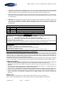
8W Model ONLY

IOM – LOMOND - ZONE 1 FLAMEPROOF FLUORESCENT (ATEX)
I-LOMD-01.doc Issue 07 01/01/2021 2
Type Of Protection Ex d (flameproof)
Protection Standards EN 60079-0, EN 60079-1, EN 50281-1-1
Area Classification Zone 1 and Zone 2 areas to EN 60079-10-1
Zone 21 and Zone 22 areas to EN 60079-10-2
Installation EN 60079-14
Certificate EC Type Examination Certificate Sira05ATEX1299X
Equipment Coding Ex de IIB T5 / T6 T**°C (Tamb see Table 1)
ATEX Coding II 2GD T100°C or T85°C
Ingress Protection IP66 to EN 60529
CE Mark
The CE marking of this product applies to "The Electrical Equipment (Safety) Regulations
2006", "The Electromagnetic Compatibility Regulations 2004", the “Waste Electrical and
Electronic Equipment Regulations 2006” and the "Equipment and Protective Systems intended
for use in Explosive Atmospheres Regulations 1996". [This legislation is the equivalent in UK
law of EU directives 2014/35/EU, 2014/30/EU, 2012/19/EU and 2014/34/EU respectively].
The Equipment is declared to meet the provisions of the ATEX directive (2014/34/EU) by
reason of the EC Type Examination and compliance with the Essential Health and Safety
Requirements.
M Poutney Technical Manager
IMPORTANT
1. Read this leaflet carefully before commencing to install the luminaire and retain it for future reference.
2. Check the rating label to ensure that the luminaire is suitable for the supply provided.
3. The luminaire must be installed in accordance with the recognised code of practice e.g. EN60079-14.
4. High voltage insulation testing may be carried out, but the test voltage must not exceed 500V DC.
WARNING: Any faults to earth within the luminaires may result in permanent damage to the electronic control unit.
This possibility can be avoided by shorting the live and neutral cables together and applying the test voltage between
this connection and earth.
5. The luminaire MUST be earthed
6. The operating temperature range for the luminaire is shown on the rating label. The luminaire should not be used outside
these temperatures.
7. If the luminaire is to be installed in areas of high vibration, please consult the manufacturer.
8. Under NO circumstances should a luminaire be opened, even when isolated, when an explosive gas or dust environment is
present.
9. Do not use excessive force on plastic components.
10. The luminaires are designed and constructed to EN60598.
11. Prices and design are subject to alteration without notice. All products are sold subject to our conditions of sale, copies of
which are available on request. We reserve the right to change characteristics of our products. All data is for guidance only.
GENERAL INSTALLATION NOTES.
1. Do not attempt installation until you are familiar with all warnings, precautions and procedures within this instruction sheet.
2. Refer to the wiring diagrams for correct installation.
3. Do not over tighten fasteners into plastic parts.
4. Ensure that the mains cable connectors are correctly secured to the terminal block(s). Only one conductor should be fitted to
each terminal block. All terminal screws should be fully tightened whether a conductor is fitted or not.
5. Blanking plugs and cable glands must be of the correct type and must be fitted to the manufacturer’s specification to ensure
that the seals prevent the ingress of moisture or dust and so maintain the luminaire’s IP rating.
GENERAL MAINTENANCE NOTES.
1. IMPORTANT. Isolate the luminaire from both switched and unswitched mains supplies before carrying out any maintenance
work.
2. Lamps must be changed at the intervals recommended by the lamp manufacturer.
3. It is essential that all luminaires together with their associated cables, glands, etc. which make up the installation are
maintained in such a manner as to ensure the integrity of the protection to which it is designed.
SPECIAL CONDITIONS FOR SAFE USE
The Lomond and Lomond E ranges of luminaires shall only be installed in areas where there is a
low risk of impact.

IOM – LOMOND - ZONE 1 FLAMEPROOF FLUORESCENT (ATEX)
I-LOMD-01.doc Issue 07 01/01/2021 3
4. The frequency of inspection must be determined by the user, but should be regular enough to ensure that the luminaire
installation continues to operate in the designed manner. The more onerous the operating conditions, the more frequent the
inspections should be. It is recommended that the interval between inspections should not exceed two years.
5. Plastic components may be cleaned with water containing a small amount of detergent, followed by a clean water wash.
Surplus water can be wiped off plastic components, but they should not be wiped or polished with a dry cloth to avoid a build
up of static electricity.
6. IMPORTANT. All components that are replaced must be in accordance with the manufacturer’s specification. Failure to use
such components invalidates the certification, approval and warranty of the luminaire and may make it dangerous. NO
modification should be made to the luminaire without the knowledge and approval of the manufacturer. If in doubt, refer to
the manufacturer.
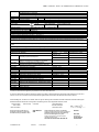
Table 1
Model Length (feet) Certification Code
8W 1 Ex d llB T6 Ta -20°C to +55°C or Ex d llC T6 Ta -20°C to +55°C
18W 2 Ex d llB T6 Ta -20°C to +55°C or Ex d llC T6 Ta -20°C to +55°C
36W 4 Ex d llB T6 Ta -20°C to +53°C or Ex d llB T5 Ta -20°C to +55°C
58W 5 Ex d llB T6 Ta -20°C to +49°C or Ex d llB T5 Ta -20°C to +55°C
70W 6 Ex d llB T6 Ta -20°C to +44°C or Ex d llB T5 Ta -20°C to +55°C
TECHNICAL DATA
Only T8 lamps should be used except for the 8W model, which uses a T5 lamp.
Total circuit watts: 1x8W=9W, 1x18W = 19W, 1x36W=37W, 1x58W=55W, 1x70W=68W
2x8W=18W, 2x18W= 41W, 2x36W=71W, 2x58W=110W, 2x70W=132W
Maximum inrush current at switch on is 20A (8W), 30A (18W), 40A (36W), 45A (58W) and 50A (70W) for < 1ms
Power factor correction is better than 0.95
The luminaire is made from aluminium (body), glass (lens), stainless steel (reflector) and galvanised steel (mounting channel).
The user must ensure that these materials are suitable for the atmosphere the luminaire will be installed in.
SPECIAL NOTES
Please consult the manufacturer if the luminaire is to be used in high vibration areas.
The luminaire is only suitable for use in areas with low impact risk.
NO ATTEMPT must be made to remove the reflector from the lampglass assembly.
The glass assembly should be kept clean.
The terminal block is suitable for cables from 0.5mm2to 4mm2. An external and internal earth is provided.
INSTALLATION AND MAINTENANCE NOTES SPECIFIC TO THIS PRODUCT.
The lampglass assembly must be removed prior to mounting the luminaire. This achieved by removing the spring nut/square
washer at the end of the channel, releasing the two screws connecting the assembly to the ballast housing and unclipping the
suspension cable. The mounting channel should be secured in any orientation using a minimum of two fixing points. The
luminaire should then be reassembled with lamps fitted, as described below. Fit the spring nut/ square washer in the undercut in
the lampglass end casting to prevent movement due to vibration.
Two M20 cable entry points are provided for fitting approved flameproof cable entry devises, with or without the use of approved
flameproof thread adaptors. Care should be taken to ensure sealing of the glands is adequate to maintain the IP66/67 integrity.
LAMPING AND RELAMPING
1. Remove the lampglass assembly as described above. The lampglass should be jacked out as the screws are progressively
slackened, if not jar the ballast housing slightly to free it. Allow the lampglass to hang on the suspension cord.
2. Disconnect the plug and socket connection to the geartray. Slacken the geartray securing screw to allow the geartray to be
withdrawn.
3. The lamps can be fitted by locating their pins in the lampholders and rotating them through 90°. The geartray assembly can
then be installed in the lampglass assembly by reversing the above process.
4. Apply a smear of non-setting grease to the flamepath on the lampglass assembly before fitting it to the ballast housing. These
two parts should be aligned carefully and the bolts should tighten without difficulty. If not, attempt to improve the alignment.
5. Secure the assembly by alternately tightening the securing screws. Some resistance may be encountered because of air
locking of the enclosure. The assembly is completed when the lampglass assembly is fully home and compressing the
sealing ring.
GENERAL CARE
Flamepaths should be cleaned using a non-metallic scraper and/or suitable non-corrosive cleaning fluids.
Parts which are cracked, damaged or worn must be replaced with the correct parts supplied by the manufacturer.

IOM – LOMOND - ZONE 1 FLAMEPROOF FLUORESCENT (ATEX)
I-LOMD-01.doc Issue 07 01/01/2021 4
HEALTH AND SAFETY AT WORK etc. ACT 1974
In the United Kingdom all equipment must be installed, operated and disposed of (as required) within the legislative requirements
of the Health and Safety at Work etc. Act 1974. Leaflet No. HSS L1 refers to the Company’s obligation and is available on
request.
It is the responsibility of the user to select, install, operate and maintain the equipment in accordance with the relevant legislation
and appropriate codes of practice.
Disposal of Material
Any disposal must satisfy the requirements of the WEEE directive [2012/19/EU] and therefore must not be treated as commercial
waste. The unit is mainly made from incombustible materials. The control gear contains plastic, resin and electronic
components. All electrical components may give off noxious fumes if incinerated.
To comply with the Waste Electrical and Electronic Equipment directive 2012/19/EU the
apparatus cannot be classified as commercial waste and as such must be disposed of or
rec
y
cled in such a manner as to reduce the environmental im
p
act.

IOM – LOMOND - ZONE 1 FLAMEPROOF FLUORESCENT (ATEX)
I-LOMD-01.doc Issue 07 01/01/2021 5
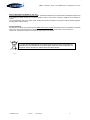
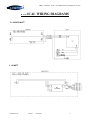
TYPICAL WIRING DIAGRAMS
2 x 18/36/58 WATT
1 x 8 WATT

IOM – LOMOND - ZONE 1 FLAMEPROOF FLUORESCENT (ATEX)
I-LOMD-01.doc Issue 07 01/01/2021 6

IOM – LOMOND - ZONE 1 FLAMEPROOF FLUORESCENT (ATEX)
I-LOMD-01.doc Issue 07 01/01/2021 7
EU-Declaration of conformity
UE-Déclaration de conformité
EU-Konformitätserklärung
Manufacturer Chalmit Address 388 Hillin
g
ton Road, Glas
g
ow. G52 4BL Scotland UK
Product Lomond Luminaire.
EC - Type Examination Certificate Sira05ATEX1299X
Notified Body CSA Group Netherlands B.V. 2813
ATEX Coding II 2 GD ATEX Classification Group II Category 2 GD
Equipment Codin
g
Ex d IIB T6 or T5 or
(
llC T6
)
T100°C or T85°
In
g
ress protection IP66/67
The technical basis, with respect to equivalence of
La base technique, en ce qui concerne l'équivalence de
Die technische Grundlage hinsichtlich der Normen
Protection Standards EN 60079-0, EN 60079-1, EN 50281-1-1
Area Classification EN 60079-10-1and EN 60079-10-2
of compliance with the EHSRs is valid as there are no changes which materially affect the state of technological progress of the product.
en conformité avec les EESS est valide puisqu'il n'y a aucun changement qui affecte matériellement l'état de l'évolution technologique du
produit.
zur Erfüllung der GSGA ist gegeben, da keine Änderungen erfolgt sind, die einen Einfluss auf den technischen Stand des Produkts haben.
Terms of the directive: Standard & Date Certified to Standards Date Declared to
Prescription de la directive: Standard & date certifiée à Normes date Déclaré
Bestimmungen der Richtlinie: Standard & Datum
Zertifiziert nach
Standards Datum erklärt
2014/34/EU Equipment and protective systems intended for use in
potentially explosive atmospheres.
EN 60079-0: 2004 2012
EN 60079-1: 2004 2014
2014/34/UE Appareils et les systèmes de protection destinés à être
utilisés en atmosphères potentiellement explosibles.
EN 50281-1-1: 1999
2014/34/EU Geräte und Schutzsysteme zur bestimmungs-
gemäßen Verwendung in explosionsfähigen Bereichen.
2014/30/EU Electroma
g
netic compatibilit
y
EN 55015 : 2013
2014/30/UE Compatibilité électroma
g
nétique EN 61547 : 2009
2014/30/EU Elektromagnetische Verträglichkeit EN 61000-3-2 : 2014
2014/35/EU Low volta
g
e equipment EN 60598-1 : 2015
2014/35/UE Équipements électriques à bas voltage EN 60598-2-5 : 2015
2014/35/EU Niederspannun
g
s
g
eräte / -s
y
steme EN 60529 : 1992
2012/19/EU Waste of electrical and electronic equipment
2012/19/UE Déchets d'équipements électriques et électroniques
2012/19/EU Entsorgung der elektrischen und elektronischen Geräte
/ Systeme
2011/65/EU RoHS II Directive
On behalf of the Chalmit, I declare that, on the date the equipment accompanied by this declaration is placed on the market, the equipment
conforms to all technical and re
g
ulator
y
requirements of the above listed directives.
En tant que représentant du fabricant Chalmit, je déclare qu'à la date où les équipements accompagnant cette déclaration sont mis sur le
marché, ceux-ci sont conformes à toutes les dispositions ré
g
lementaires et techniques des directives énumérées ci-dessus.
Hiermit bestätige ich, im Namen von Chalmit, dass am Tag der Lieferung des Produkts/der Produkte zusammen mit dieser Erklärung das
Gerät/die Geräte alle technischen und re
g
ulativen Anforderun
g
en der oben auf
g
eführten Direktiven erfüllt.
Name and Date Mark Poutney 01/01/2021 Technical Manager
Nom et Date Directeur technique
Name und Datum Technischer Leiter
Qualit
y
Assurance Notification b
y
: SGS FIMKO OY Qualit
y
Mana
g
ement S
y
stem Acreditation: ISO 9001
Notification d'assurance qualité par: 0598 Système de Management Qualité Accréditation:
Qualitätssicherun
g
snotifikation durch: Qualitätsmana
g
ements
y
stem Akkreditierun
g
:
Environmental Mana
g
ement S
y
stem. ISO 14001
Système de gestion de l'environnement. by/par/durch
Umwelt kontroll s
y
stem. Lo
y
d's Re
g
ister
Certificate No./Certificat N°/Zertifikat Nr. LRQ 4005876

IOM – LOMOND - ZONE 1 FLAMEPROOF FLUORESCENT (ATEX)
I-LOMD-01.doc Issue 07 01/01/2021 8
-
 1
1
-
 2
2
-
 3
3
-
 4
4
-
 5
5
-
 6
6
-
 7
7
-
 8
8


Chalmit lighting Lomond Fluorescent | ATEX Guide d'installation
- Taper
- Guide d'installation
dans d''autres langues
Documents connexes
Autres documents
-
 Hadar Lighting HDN106 Guide d'installation
-
Emerson MS Motor Starters Certificate
-
Eaton eLLB20 Fluorescent Mode d'emploi
-
KILLARK L1L Series Guide d'installation
-
Videotec MAXIMUS MBX Manuel utilisateur
-
WIKA TC10-L tag:model:TR10-L Mode d'emploi
-
Sera Diaphragm monitoring for ML KM Mode d'emploi
-
Eaton eLLM 92 NE Operating Instructions Manual
-
KNF N 922 ST Ex Manuel utilisateur
