
4 131 022-Ed.03/2012.09 DDD
Wilo-Star-Z 20/1, 25/2, 25/2 DM, 25/6, ZD 25/6
D Einbau- und Betriebsanleitung
GB Installation and Maintenance Instructions
F Notice de mise en service et de montage
IIstruzioni di montaggio, uso e manutenzione
E Instrucciones de instalación
y funcionamiento
S Installations- och skötselinstruktioner
CZ Návod k montáži a obsluze
GR Οδηγίες εγκ
α
τάστ
α
σης κ
α
ι λειτουργί
α
ς
https://tm.by
Интернет-магазин TM.by

Fig. 1
Fig. 2
3Ù400 V
Fig. 4Fig. 3
https://tm.by
Интернет-магазин TM.by

N
L
N
L
N
L
N
L
/
/
1 230 V
50 Hz
N
L
Fig. 5
Fig. 5
Fig. 5 b
Fig. 5 a
Fig. 5 c
https://tm.by
Интернет-магазин TM.by

https://tm.by
Интернет-магазин TM.by

DEUTSCH
1. Allgemeines . . . . . . . . . . . . . . . . . 3
2. Sicherheit . . . . . . . . . . . . . . . . . . . 3
3. Transport und
Zwischenlagerung . . . . . . . . . . . . 5
4. Beschreibung von Erzeugnis
und Zubehör . . . . . . . . . . . . . . . . . 5
5. Aufstellung/Einbau . . . . . . . . . . . 6
6. Inbetriebnahme . . . . . . . . . . . . . . 7
7. Wartung . . . . . . . . . . . . . . . . . . . . . 8
8. Störungen, Ursachen
und Beseitigung . . . . . . . . . . . . . . 8
9. Ersatzteile ................... 8
D
1. Généralité . . . . . . . . . . . . . . . . . . . 15
2. Sécurité . . . . . . . . . . . . . . . . . . . . . 15
3. Transport et stockage
intermédiaire . . . . . . . . . . . . . . . . 16
4. Description du produit
et de ses accessoires . . . . . . . . . 17
5. Installation/montage . . . . . . . . . 17
6. Mise en service . . . . . . . . . . . . . . . 19
7. Entretien . . . . . . . . . . . . . . . . . . . . 19
8. Défauts,
causes et remèdes . . . . . . . . . . . 19
9. Pièces détachées . . . . . . . . . . . . . 20
F
1. Generalità ................... 20
2. Sicurezza .................... 21
3. Trasporto e magazzinaggio . . . 23
4. Descrizione del prodotto
eaccessori................... 23
5. Montaggio/
Installazione . . . . . . . . . . . . . . . . . 24
6. Messa in esercizio . . . . . . . . . . . . 25
7. Manutenzione . . . . . . . . . . . . . . . 26
8. Blocchi, cause e rimedi . . . . . . . . 26
9. Ricambi ..................... 27
I
1. General...................... 9
2. Safety....................... 9
3. Transport and Storage . . . . . . . . 10
4. Description of
Product and Accessories . . . . . . 11
5. Siting/Installation . . . . . . . . . . . . 11
6. Commissioning . . . . . . . . . . . . . . 13
7. Maintenance . . . . . . . . . . . . . . . . . 13
8. Fault finding –
causes and remedies . . . . . . . . . 14
9. Spareparts .................. 14
GB
1
https://tm.by
Интернет-магазин TM.by

DEUTSCH
1. Generalidades . . . . . . . . . . . . . . . 28
2. Seguridad . . . . . . . . . . . . . . . . . . . 28
3. Transporte
y almacenamiento . . . . . . . . . . . . 30
4. Aplicaciones . . . . . . . . . . . . . . . . . 30
5. Instalación/Montaje . . . . . . . . . . 31
6. Puesta en marcha . . . . . . . . . . . . 32
7. Mantenimiento . . . . . . . . . . . . . . 33
8. Averías, causas y solución . . . . . 33
9. Repuestos ................... 33
E
1. Allmän information . . . . . . . . . . . 34
2. Säkerhet . . . . . . . . . . . . . . . . . . . . 34
3. Transport och
lagring . . . . . . . . . . . . . . . . . . . . . . 36
4. Beskrivning av produkten
och tillbehören . . . . . . . . . . . . . . . 36
5. Installation/montering . . . . . . . . 36
6. Drift . . . . . . . . . . . . . . . . . . . . . . . . 38
7. Underhåll . . . . . . . . . . . . . . . . . . . . 38
8. Fel, orsaker och åtgärder . . . . . . 39
9. Reservdelar .................. 39
S
1. Γενικά....................... 46
2. Aσφάλεια ................... 46
3. Μεταφορά και προ-σωρινή
αποθήκευση ................. 48
4. Περιγραφή προϊόν-τος και
εξοπλισµού.................. 48
5. Τοποθέτηση/
Εγκατάσταση ................ 49
6. Θέση σε λειτουργία . . . . . . . . . . 50
7. Συντήρηση .................. 51
8. Βλάβες, αίτια και
αντιµετώπιση . . . . . . . . . . . . . . . . 51
9. Ανταλλακτικά . . . . . . . . . . . . . . . . 52
GR
1. Obecné informace . . . . . . . . . . . . 40
2. Bezpecnostní pokyny . . . . . . . . . 40
3. Preprava a skladování . . . . . . . . . 42
4. Popis výrobku a príslušenství . . 42
5. Instalace/montáž . . . . . . . . . . . . . 43
6. Uvedení do provozu . . . . . . . . . . 44
7. Údržba ...................... 45
8. Poruchy, príciny
a odstranování . . . . . . . . . . . . . . . 45
9. Náhradní díly . . . . . . . . . . . . . . . . 45
CZ
2
https://tm.by
Интернет-магазин TM.by

DEUTSCH
3
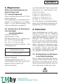
1. Allgemeines
Einbau und Inbetriebnahme nur
durch Fachpersonal
1.1 Verwendungszweck
Diese Umwälzpumpen sind nur für Trink-
wasser geeignet.
Die Umwälzpumpen der Baureihe Star-Z
werden zur Förderung von Flüssig-
keiten im Trink-/Brauchwasser- und
Lebensmittelbereich eingesetzt.
1.2 Angaben über die Erzeugnisse
1.2.1 Anschluß-
und Leistungsdaten
maximal zulässiger
Betriebsdruck: 10 bar
Mindestzulaufdruck am Saugstutzen
bei 40 °C: 0,5 bar (50 kPa)
bei 65 °C: 0,2 bar (20 kPa)
zulässiger Temperatur-Bereich des
Fördermediums:
Maximal zulässige
Umgebungstemperatur: 40 °C
Anschlußspannung: siehe Typenschild
aufgenommene Leistung P1:
siehe Typenschild
max. Motordrehzahl: siehe Typenschild
Nennweite der Anschlußrohre (Ver-
schraub.-Pumpe).
Z 20/1: R1/2, Ø 15 (G: R 1)
Z 25/2: R 1, Ø 28 (G: R1½)
Z 25/6: R 1, Ø 28 (G: R1½)
ZD 25/6: R 1, Ø 28 (G: R 1½)
Zur Vermeidung von Kavitationsgeräu-
schen ist der Mindest-Zulaufdruck am
Saugstutzen der Pumpe einzuhalten.
2. Sicherheit
Diese Betriebsanleitung enthält grund-
legende Hinweise, die bei Aufstellung
und Betrieb zu beachten sind. Daher ist
diese Betriebsanleitung unbedingt vor
Montage und Inbetriebnahme vom
Monteur sowie dem zuständigen Betrei-
ber zu lesen. Es sind nicht nur die unter
diesem Hauptpunkt Sicherheit aufge-
führten allgemeinen Sicherheitshinweise
zu beachten, sondern auch die unter
den folgenden Hauptpunkten eingefüg-
ten, speziellen Sicherheitshinweise.
2.1 Kennzeichnung von Hinweisen
in der Betriebsanleitung
Die in dieser Betriebsanleitung ent-
haltenen Sicherheitshinweise, die bei
Nichtbeachtung Gefährdungen für Per-
sonen hervorrufen können, sind mit
dem allgemeinen Gefahrensymbol
+ 2°C bis +65°C
Brauchwassersysteme
https://tm.by
Интернет-магазин TM.by

DEUTSCH
4
bei Warnung vor elektrischer Spannung
mit
besonders gekennzeichnet.
Bei Sicherheitshinweisen, deren Nicht-
beachtung Gefahren für die Pumpe/-
Anlage und deren Funktion hervorrufen
können, ist das Wort
eingefügt.
2.2 Personalqualifikation
Das Personal für die Montage muß
die entsprechende Qualifikation für
diese Arbeiten aufweisen.
2.3 Gefahren bei Nichtbeachtung
der Sicherheitshinweise
Die Nichtbeachtung der Sicherheits-
hinweise kann eine Gefährdung für
Personen und Pumpe/Anlage zur Folge
haben. Die Nichtbeachtung der Sicher-
heitshinweise kann zum Verlust jeglicher
Schadenersatzansprüche führen.
Im einzelnen kann Nichtbeachtung
beispielsweise folgende Gefährdungen
nach sich ziehen:
– Versagen wichtiger Funktionen der
Pumpe/Anlage,
– Gefährdungen von Personen durch
elektrische und mechanische Ein-
wirkungen.
ACHTUNG!
2.4 Sicherheitshinweise für den
Betreiber
Die bestehenden Vorschriften zur Un-
fallverhütung sind zu beachten.
Gefährdungen durch elektrische Ener-
gie sind auszuschließen. Vorschriften
des VDE und der örtlichen Energiever-
sorgungsunternehmen beachten.
2.5 Sicherheitshinweise für
Inspektions- und Montage-
arbeiten
Der Betreiber hat dafür zu sorgen,
daß alle Inspektions- und Montage-
arbeiten von autorisiertem und quali-
fiziertem Fachpersonal ausgeführt
wer
den,
das sich durch eingehendes
Studium der Betriebsanleitung aus-
reichend informiert hat.
Grundsätzlich dürfen Arbeiten an der
Pumpe/Anlage nur im Stillstand durch-
geführt werden.
2.6 Eigenmächtiger Umbau und
Ersatzteilherstellung
Veränderungen der Pumpe/Anlage
sind nur nach Absprache mit dem
Hersteller zulässig. Originalersatzteile
und vom Hersteller autorisiertes Zu-
behör dienen der Sicherheit. Die
Verwendung anderer Teile kann die
Haftung für die daraus entstehenden
Folgen aufheben.
https://tm.by
Интернет-магазин TM.by

DEUTSCH
5
2.7 Unzulässige Betriebsweisen
Die Betriebssicherheit der gelieferten
Pumpe/Anlage ist nur bei bestim-
mungsmäßiger Verwendung entspre-
chend Abschnitt 1 der Betriebsan-
leitung gewährleistet. Die im Katalog/
Datenblatt angegebenen Grenzwerte
dürfen auf keinen Fall über- bzw.
unterschritten werden.
3. Transport und
Zwischenlagerung
Bei Transport und Zwischenlagerung
ist die Pumpe gegen Feuchtigkeit
und mechanische Beschädigung zu
schützen.
4. Beschreibung
von Erzeugnis und
Zubehör
4.1 Beschreibung der Brauch-
wasserpumpen
Die Umwälzpumpen der Baureihe
Star-Z sind speziell auf die Betriebs-
verhältnisse in Trink-/Brauchwasser-
Zirkulationssystemen abgestimmt.
Sie sind durch Werkstoffauswahl und
Konstruktion korrosionsfest gegen alle
Bestandteile im Trink-/Brauchwasser.
ACHTUNG!
Drehzahl-Umschaltung: Der Pumpen-
typ Z 25/6 und ZD 25/6 hat einen
Drehknopf am Klemmenkasten für eine
manuelle Umschaltung in 3 Drehzahl-
stufen [1 – 2 – 3]. In der Mindeststufe
wird die Drehzahl auf etwa 40 ...50%
der maximalen Drehzahl reduziert.
Die Stromaufnahme reduziert sich
dabei auf etwa 50 %.
Besonderheiten an den Pumpen
Bei einer Doppelpumpe sind die beiden
Einstecksätze identisch aufgebaut und
werden in einem gemeinsamen Pum-
pengehäuse mit integrierter Umschalt-
klappe montiert.
Jede Pumpe kann im Einzelbetrieb
laufen, aber auch beide Pumpen
gleichzeitig im Parallelbetrieb. Die
Betriebsarten sind Haupt-/Reserve-
betrieb oder Additions-/Spitzenlast-
betrieb. Die Einzelaggregate können für
unterschiedliche Leistungen ausgelegt
werden. Mit der Doppelpumpen kann
so eine Anlage auf individuelle Be-
triebssituationen abgestimmt werden.
4.2 Lieferumfang
– Pumpe komplett,
– Einbau- und Betriebsanleitung.
4.3 Zubehör
Verfügbares bzw. erforderliches Zu-
behör muß gesondert bestellt werden.
– Einlegeteile für den Rohranschluß
bei Verschraubungspumpen,
https://tm.by
Интернет-магазин TM.by

DEUTSCH
6
– Steckmodul S1R-h, nur für blockier-
stromfeste EM-Typen, nicht für
Z 25/6.
5. Aufstellung/Einbau
5.1 Montage
– Einbau erst nach Abschluß aller
Schweiß- und Lötarbeiten und der
erforderlichen Spülung des Rohr-
systems vornehmen. Schmutz kann
die Pumpe funktionsunfähig machen.
–
Die Pumpe an gut zugänglicher Stelle
montieren, so daß eine spätere Über-
prüfung oder ein Austausch leicht
möglich ist.
– Wird die Pumpe in ein Trink-/
Brauchwasser-Zirkulationssystem
eingebaut, so muß druckseitig eine
Rückschlagklappe installiert werden.
– Der Einbau von Absperrarmaturen
vor und hinter der Pumpe ist zu
empfehlen. Damit wird bei einem
evtl. Austausch der Pumpe ein Ab-
lassen und Wiederauffüllen der
Anlage erspart. Die Armaturen sind
so zu montieren, daß Leckwasser
nicht auf den Pumpenmotor oder
Klemmenkasten tropfen kann.
– Spannungsfreie Montage mit waage-
recht liegender Pumpenwelle durch-
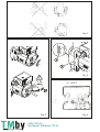
führen. Einbaulagen nach Bild 1
einhalten.
– Der Richtungspfeil auf dem Pumpen-
gehäuse zeigt die Fließrichtung an
(Bild 2, Pos. 1).
Star- Z 25/2 DM:
Der Motorklemmenkasten darf nicht
nach unten zeigen, da sonst leicht
Wasser eindringen kann. Evtl. muß
das Motorgehäuse nach Lösen der
Inbusschrauben verdreht werden.
Die Gehäuse-Flachdichtung nicht
beschädigen.
– Bei Pumpen, die mit einem Steck-
modul aus- oder nachgerüstet sind,
darf der Luftzugang zum Modul
nicht eingeschränkt werden.
Bei Anlagen, die isoliert werden, darf
nur das Pumpengehäuse einisoliert
werden. Die Schwitzwasserlöcher am
Motorflansch müssen offen bleiben
(Bild 2, Pos. 2).
5.2 Elektrischer Anschluß
– Der elektrische Anschluß
ist von einem bei örtlichen
EVU zugelassenen Elektro-
installateur und entspre-
chend den geltenden VDE-
Vorschriften auszuführen.
– Der elektrische Anschluß muß nach
VDE 073 0/Teil 1 über eine feste
Anschlußleitung erfolgen, die mit einer
Steckvorrichtung oder einem allpoli-
gen Schalter mit mindestens 3 mm
Kontaktöffnungsweite versehen ist.
ACHTUNG!
ACHTUNG!
ACHTUNG!
https://tm.by
Интернет-магазин TM.by

DEUTSCH
7
– Um den Tropfwasserschutz und
die Zugentlastung der Stopfbuchse
sicherzustellen, ist eine Anschluß-
leitung mit ausreichendem Außen-
durchmesser zu verwenden (z. B.
H 05 V V-F 3 (4) G 1,5).
– Die Anschlußleitung ist so zu ver-
legen, daß in keinem Fall die Rohr-
leitung und/oder das Pumpen- und
Motorgehäuse berührt werden.
– Stromart und Spannung des Netz-
anschlusses überprüfen,
– Typenschilddaten der Pumpe
beachten,
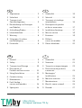
– Netzanschluß entsprechend dem
Schaltbild (Bild 4/5) ausführen:
– 4: 3~400 V, blockierstromfest,
– 5: 1~230 V, blockierstromfest,
– Erdung beachten.
6. Inbetriebnahme
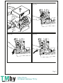
6.1 Füllen und Entlüften
Anlage sachgemäß füllen. Eine Ent-
lüftung des Pumpenrotorraumes er-
folgt selbsttätig bereits nach kurzer
Betriebsdauer. Kurzzeitiger Trockenlauf
schadet der Pumpe nicht. Falls jedoch
eine direkte Entlüftung des Rotorraumes
erforderlich sein sollte, ist wie folgt zu
verfahren:
– Pumpe ausschalten,
– Rohrleitung druckseitig schließen,
– Entlüftungsschraube mit passendem
Schraubendreher vorsichtig öffnen
(Bild 3),
–Je nach Temperatur des
Fördermediums und System-
drucks kann beim Öffnen
der Entlüftungsschraube
heißes Fördermedium in
flüssigem oder dampfför-
migem Zustand austreten
bzw. unter hohem Druck
herauschießen.
Es besteht Verbrühungs-
gefahr!
– Elektrische Teile vor austretendem
Wasser schützen,
– Pumpe einschalten,
– Nach 15 … 30s Entlüftungsschraube
wieder schließen,
– Absperrorgan wieder öffnen.
Die Pumpe kann bei geöffneter
Verschlußschraube in Abhängigkeit
von der Höhe des Betriebsdruckes
blockieren.
– Je nach Betriebszustand
der Pumpe bzw. der
Anlage (Temperatur des
Fördermediums) kann die
gesamte Pumpe sehr heiß
werden.
Es besteht Verbrennungs-
gefahr bei Berührung der
Pumpe!
ACHTUNG!
https://tm.by
Интернет-магазин TM.by

DEUTSCH
6.2 Einstellen
–Drehrichtungskontrolle bei Dreh-
strommotoren:
Vor Kontrolle der Drehrichtung Ver-
schlußschraube auf der Stirnseite
des Motors entfernen. Durch kurz-
zeitiges Einschalten prüfen, ob die
Drehrichtung der Pumpe mit dem
Pfeil auf dem Typenschild überein-
stimmt. Bei falscher Drehrichtung
2 Phasen vertauschen.
7. Wartung
Vor Wartung- oder Instandset-
zungsarbeiten Pumpe span-
nungsfrei schalten und gegen
unbefugtes Wiedereinschalten
sichern.
8. Störungen, Ursachen
und Beseitigung
8.1 Pumpe läuft bei eingeschalte-
ter Stromzufuhr nicht:
– Elektrische Sicherungen überprüfen,
– Spannung an der Pumpe prüfen
(Typenschilddaten beachten),
– Kondensatorgröße prüfen (Typen-
schilddaten beachten).
– Motor ist blockiert, z. B. durch Ab-
lagerungen.
Abhilfe: Zentrale Verschlußschraube
entfernen und Gängigkeit des Pumpen-
rotors durch Drehen des geschlitzen
Wellenendes mit Hilfe eines Schrauben-
drehers prüfen bzw. deblockieren.
Sicherheitsmaßnahmen wie
bei 6.1 beachten!
Bei hohen Wassertempe-
raturen und Systemdrücken
Absperrarmaturen vor und
hinter der Pumpe schließen.
Pumpe vorher abkühlen
lassen.
8.2 Pumpe macht Geräusche
– Bei Kavitation durch unzureichen-
den Zulaufdruck.
Abhilfe: System-Vordruck innerhalb
des zulässigen Bereiches erhöhen.
Läßt sich die Betriebsstörung nicht
beheben, wenden Sie sich bitte an
Ihren Sanitär- und Heizungsfach-
handwerker oder an den Wilo-
Kundendienst.
9. Ersatzteile
Bei Ersatzteilbestellungen sind sämt-
liche Daten des Typenschildes anzu-
geben.
Technische Änderungen vorbehalten.
8
https://tm.by
Интернет-магазин TM.by

ENGLISH
1. General
Installation and service by quali-
fied personnel only
1.1 Fields of Application
This circulator is suitable for drinking
water only. Series Star-Z circulating
pumps are suitable of handling liquids
in the fields of service/drinking water
and food-related liquids.
1.2 Product Information
1.2.1 Technical Data
Maximum working pressure: 10 bar
Minimum inlet pressure at suction port
at 40 °C: 0.5 bar (50 kPa)
at 65 °C: 0.2 bar (20 kPa)
Permissible temperature range of fluid:
Maximum permissible ambient tem-
perature: 40°C.
Mains supply voltage: refer to name
plate.
Input power P1: refer to name plate.
Max. motor speed: refer to name plate
Pipe connection size: (screw ended
pump)
Z 20/1: R1
/2, DN 15 (G: R 1)
Z 25/2: R 1, DN 28 (G: R1
1
/2)
Z 25/6: R 1, DN 28 (G: R1
1
/2)
ZD 25/6: R 1, DN 28 (G: R 1½)
The minimum inlet pressure at the
pump suction port must be maintained
to avoid cavitation noise.
2. Safety
These instructions contain basic refe-
rence to safety aspects which must
be strictly adhered to. It is therefore
imperative for the Installer and the
Operator to carefully read these
instructions prior to installation and
commissioning. Please observe, not
only the safety rules under the main
heading safety considerations, but also
those added and specially marked
under the ensuing headers.
2.1 Safety Symbols contained in
these Instructions
Safety rules contained herein which, if
not complied with, may be harmful to
persons are specially highlighted by
the following danger symbols:
Danger from general causes:
Danger from electrical causes:
Safety references which, if not com-
plied with, may cause damage to the
pump/plant or impair its function are
highlighted by the word:
ATTENTION!
+2°C up to +65°C
Service water systems
9
https://tm.by
Интернет-магазин TM.by

ENGLISH
10
2.2 Trade Qualifications
Only suitably qualified personnel may
work on this equipment.
2.3 Dangers from Non-Observance
of Safety Rules
Non-observance of safety reference
may cause bodily harm to persons or
damage to the plant. Failure to comply
with safety reference could invalidate
warranty and/or damage claims. In
detail, non-compliance may, for exam-
ple, cause the following dangerous
situations:
– failure of vital plant functions or
damage to pump/plant,
– causing personal injury from electri-
cal and/or mechanical causes.
2.4 Safety Consideration
for the Operator
Local regulations for the prevention of
accidents must be observed.
Danger from electrical energy must be
excluded (conforming to local or gene-
ral regulations such as IEC, VDE, etc.).
2.5 Safety Considerations for
Inspections and Installation
Work
It is the Operator’s responsibility to
ensure that inspections and installa-
tion work are carried out by authorized
and qualified personnel only, having
themselves made fully conversant with
these instructions.
Work must principally be carried out
only with the plant switched off and at
complete standstill.
2.6 Arbitrary Alterations and
Spare Parts Procurement
Any alterations to the plant are only
permitted in agreement with the
manufacturers. Original spare parts
and authorized accessories serve
safety and reliability. The use of un-
authorized parts could invalidate any
claims for consequential damages.
2.7 Non-Permissible Operating
Conditions
Operational safety of the plant is only
ensured if used in accordance with
Chapter 1 of these instructions. The
limits stated in the catalogue/data
sheets must not be exceeded under
any circumstances.
3. Transport and
Storage
The pump must be protected from
moisture and mechanical damage at
all time during transport and interme-
diate storage.
ATTENTION!
https://tm.by
Интернет-магазин TM.by

ENGLISH
11
4. Description of
Product and
Accessories
4.1 Description of Water Service
Pumps
Series Star-Z circulating water service
pumps have been specially designed
for use in conjunction with domes-
tic/drinking water service systems.
They are, by material selection and
design, corrosion proofed against any
residual parts in domestic/drinking
water. Speed setting: Z 25/6 and ZD
25/6 pump is equipped with a rotary
switch in the terninal box to enable
manual; 3-speed control [1 – 2 – 3)].
At minimum speed the maximum
speed is reduced to approx.
40 ...50%. The power input is reduced
to approximately 50 %.
Particular features of the pumps
Double pumps contain two identically
constructed pump heads in a com-
mon pump housing with integrated
change-over flap. Each pump can run
in single mode, and both pumps can
also run simultaneously in parallel
mode. The operating modes are
main/reserve operation or incremen-
tal/peak-load operation. The pump
heads can be selected of different
capacities. Double pumps are suita-
ble of adapting a pipe system to suit
individual load characteristics.
4.2 Scope of Supply
– Pump, complete.
– Installation and Operating
Instructions.
4.3 Accessories
Accessories available and/or required
on separate order:
– Union for pipe connections,
– S1R-h plug-in timer module for
1-phase
motors only, except Z 25/6.
5. Siting/Installation
5.1 Installation
– Install pump only after all weld-
ing /soldering on the pipe system is
completed and the pipe system has
been thoroughly flushed out to be
clear of foreign matter and impu-
rities, as these may cause damage
to the pump.
– Mount pump in an easily accessible
position in order to facilitate later in-
spection and exchange.
– If used to handle domestic /drinking
water a non-return valve must be
provided and installed at the dis-
charge side.
– To avoid draining and re-filling the
whole of the pipe system on ex-
change of pump it is recommended
to provide and install isolating valves
at suction and discharge ports of the
pump, to be positioned in such a
way to prevent leakage dripping on
the pump motor or its terminal box.
https://tm.by
Интернет-магазин TM.by

ENGLISH
12
– Pump to be mounted with the shaft
in the horizontal plane in such a way
that it is not stressed by the pipe-
work. Observe mounting positions
as shown in Fig. 1.
– The arrow on the pump housing
indicates direction of flow (Fig. 2,
Pos. 1).
Star- Z 25/2 DM:
The motor terminal box must not face
downwards to avoid possible moisture
entry. If necessary, rotate pump head
after undoing the screws holding the
stator housing.
Take care not to damage the housing
gasket.
– Due care must be given that free
ventilation is not restricted to pumps
equipped or refitted with plug-in
modules.
Thermal insulation of pump, if applied,
must be restricted to the pumps hous-
ing only. Ensure that drain holes at the
motor flange remain fully open (Fig. 2,
Pos. 2).
ATTENTION!
ATTENTION!
ATTENTION!
5.2 Electrical wiring
– Electrical work to be car-
ried out by qualified and
licensed electricians in
strict conformity to ruling
national conditions and
local regulations.
– All wiring and external switchgear to
comply with ruling local regulations
(use of conduits, all-pole switches,
air gaps, etc.) in accordance with
the latest edition of IEE wiring regu-
lations).
– In order to preserve protection against
moisture entry and to ensure a firm
gland grip the mains cable must
have a sufficiently large outside dia-
meter (f.e. H 05 V V-F 3 (4) G 1,5).
– Cable leads to be routed in such
a way to avoid any contact with pipe
work and/or pump or stator housings.
– Check available power supply and
voltage.
–Observe pump name plate data
– All wiring to be carried out according
to wiring diagram (Fig. 4/5):
– 4: 3~400/415 V,
2a:non-overloading
– 5: 1~230/240 V,
2b:non-overloading
– Observe locally ruling earthing regu-
lations.
https://tm.by
Интернет-магазин TM.by

ENGLISH
13
6. Commissioning
6.1 System filling and venting
Ensure that the pipe system is
properly filled. The pump vents itself
automatically after a short operational
period. Short-term dry-running will not
harm the pump. If necessary, the
pump can be directly vented in ac-
cordance with the following procedure:
– Switch-off pump,
– close discharge isolating valve,
– Carefully slacken and remove the
central access plug using screw-
driver (Fig. 3).
– Depending on liquid tempe-
rature and system pressure,
hot liquid or vapour can be
releases when undoing the
central access plug.
Beware!
Danger of scalding!
– Protect electrical parts from leaking
water,
– switch-on pump again,
– after 15 … 30 secs close access
plug again,
– open isolating valve again.
It is possible that the pump shaft jams
with the access plug open, depending
on system pressure.
ATTENTION!
– The pump can become
extremely hot, depending
on the operating state of
pump or pipe system (fluid
temperature).
Beware of scalding when
touching the pump!
6.2 Pre-Start Adjustments
– Direction of rotation check on
3-phase motors:
Remove central access plug at the
non-drive end of the motor. Briefly
switch on motor and check
whether sense of rotation corre-
sponds to the arrow on the name
plate; if necessary, change any two
phase wires.
7. Maintenance
Prior maintenance or repair
work switch off the pump and
secure against unauthorized
switching.
https://tm.by
Интернет-магазин TM.by

ENGLISH
14
8. Fault Findings –
Causes and Remedies
8.1 Pump is switched on, but
fails to run:
– Check power supply fuses.
– Check voltage at pump terminals
(refer to name plate data).
– Check capacitor size (refer to name
plate data!).
– Rotor shaft has jammed, e.g. by
incrustations.
Remedy: Remove central access
plug, check free movement of shaft
or free respectively at the slotted
shaft end by means of a screw-
driver.
Observe safety procedures
as for 6.1!
At high water temperatures
and system pressures, close
isolating valves at both pump
ports. First, allow pump to
cool down.
8.2 Noise
– Cavitation due to insufficient inlet
pressure.
Remedy: Increase system pressure
within permissible limits.
If the fault cannot be located or rec-
tified, please contact your nearest
Wilo representative.
9. Spare Parts
State all name plate data when order-
ing spare parts.
Technical modifications reserved.
https://tm.by
Интернет-магазин TM.by

FRANÇAIS
15
1. Généralité
Montage et entretien uniquement
par du personnel qualifié
1.1 Applications
Ce circulateur convient seulement
pour l’eau potable. Les pompes de
circulation de la gamme Star Z sont
conçues pour véhiculer des liquides
dans le domaine des eaux potables ou
sanitaires et des produits alimentaires.
1.2 Caractéristiques
1.2.1 Raccordement et puissance
Pression de service maxi admissible:
10 bar
Pression minimum à l’aspiration
à 40°C: 0,5 bar (50 kPa)
à 65°C: 0,2 bar (20 kPa)
Température admissible du fluide:
Température ambiante maxi admise:
40°C
Tension de raccordement: voir plaque
signalétique
Puissance absorbée: voir plaque sig-
nalétique
Vitesse maxi: voir plaque signalétique
Section nominale de passage des
tuyauteries (pompe à RU):
Z 20/1: R1
/2, Ø 15 (G: R 1)
Z 25/2: R 1, Ø 28 (G: R1
1
/2)
Z 25/6: R 1, Ø 28 (G: R1
1
/2)
ZD 25/6: R 1, Ø 28 (G: R 1½)
Pour éviter les bruits de cavitation, il
faut maintenir la pression à l’aspirati-
on de la pompe indiquée dans le
tableau précédent.
2. Sécurité
La présente notice contient les
instructions à respecter lors du mon-
tage et de la mise en service. C’est
pourquoi elle devra être lue attentive-
ment par le monteur et l’utilisateur. Il a
lieu d’observer non seulement ce
point principal mais aussi les pre-
scriptions de sécurité spécifiques
abordées dans les points suivants.
2.1 Signalisation des consignes
de la notice
Les prescriptions de sécurité conte-
nues dans cette notice pour mettre
en garde les personnes sont symbo-
lisées par:
en ce qui concerne l’électricité par:
+ 2 °C jusqu’à +65°C
Eau sanitaire
https://tm.by
Интернет-магазин TM.by

FRANÇAIS
16
Pour annoncer des indications de
sécurité dont la non-observation peut
occasionner un danger pour l’installa-
tion et son fonctionnement, on a intégré
le mot:
Il faut absolument tenir compte des
indications portées directement sur le
matériel telles que le sens de rotation.
2.2 Qualification du personnel
On veillera à la compétence du per-
sonnel amené à réaliser le montage.
2.3 Dangers encourus en cas de
non-observation des consignes
La non-observation des consignes
peut avoir des conséquences graves
sur la sécurité des personnes et de
l’installation et entraîner la suspension
de toute garantie. Une rigueur absolue
est exigée notamment en matière
d’électricité et de mécanique.
2.4 Conseils de sécurité à
l’utilisateur
Observer le consignes en vue d’ex-
clure tout risque d’accident. Eviter les
dangers dus au réseau électrique en
respectant les prescriptions et les
norme en vigueur.
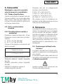
ATTENTION!
2.5 Conseils de sécurité pour les
travaux d’inspection et de
montage
L’utilisateur doit faire réaliser ces
travaux par une personne spécialisée
qualifiée ayant pris connaissance du
contenu de la notice.
2.6 Modification du matériel et
usage de pièces détachées
non agréées
Toute modification de l’installation ne
peut être effectuée qu’après l’autori-
sation préalable du fabricant. L’utilisa-
tion de pièces de rechange d’origine
et d’accessoires autorisés par le fabri-
cant garantit la sécurité. L’usage
d’autres pièces peut dégager notre
société de toute responsabilité.
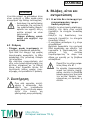
2.7 Modes d’utilisation
non-autorisés
L’utilisation du matériel livré est
prévue pour une ou des applications
précisé(e)s au chap. 1. Les valeurs
indiquées dans la fiche technique ne
doivent en aucun cas être dépassées.
3. Transport et stockage
intermédiaire
Il faut protéger la pompe contre
l’humidité pendant le transport et le
stockage avant l’utilisation.
ATTENTION!
https://tm.by
Интернет-магазин TM.by
La page est en cours de chargement...
La page est en cours de chargement...
La page est en cours de chargement...
La page est en cours de chargement...
La page est en cours de chargement...
La page est en cours de chargement...
La page est en cours de chargement...
La page est en cours de chargement...
La page est en cours de chargement...
La page est en cours de chargement...
La page est en cours de chargement...
La page est en cours de chargement...
La page est en cours de chargement...
La page est en cours de chargement...
La page est en cours de chargement...
La page est en cours de chargement...
La page est en cours de chargement...
La page est en cours de chargement...
La page est en cours de chargement...
La page est en cours de chargement...
La page est en cours de chargement...
La page est en cours de chargement...
La page est en cours de chargement...
La page est en cours de chargement...
La page est en cours de chargement...
La page est en cours de chargement...
La page est en cours de chargement...
La page est en cours de chargement...
La page est en cours de chargement...
La page est en cours de chargement...
La page est en cours de chargement...
La page est en cours de chargement...
La page est en cours de chargement...
La page est en cours de chargement...
La page est en cours de chargement...
La page est en cours de chargement...
La page est en cours de chargement...
La page est en cours de chargement...
La page est en cours de chargement...
La page est en cours de chargement...
-
 1
1
-
 2
2
-
 3
3
-
 4
4
-
 5
5
-
 6
6
-
 7
7
-
 8
8
-
 9
9
-
 10
10
-
 11
11
-
 12
12
-
 13
13
-
 14
14
-
 15
15
-
 16
16
-
 17
17
-
 18
18
-
 19
19
-
 20
20
-
 21
21
-
 22
22
-
 23
23
-
 24
24
-
 25
25
-
 26
26
-
 27
27
-
 28
28
-
 29
29
-
 30
30
-
 31
31
-
 32
32
-
 33
33
-
 34
34
-
 35
35
-
 36
36
-
 37
37
-
 38
38
-
 39
39
-
 40
40
-
 41
41
-
 42
42
-
 43
43
-
 44
44
-
 45
45
-
 46
46
-
 47
47
-
 48
48
-
 49
49
-
 50
50
-
 51
51
-
 52
52
-
 53
53
-
 54
54
-
 55
55
-
 56
56
-
 57
57
-
 58
58
-
 59
59
-
 60
60


dans d''autres langues
- italiano: Wilo Star-Z 20-1 Manuale utente
Autres documents
-
EINHELL GC-AW 6333 Manuel utilisateur
-
Metabo HWA 3500 Inox Manuel utilisateur
-
EINHELL GC-GP 6538 Manuel utilisateur
-
EINHELL GE-DP 7330 LL ECO Manuel utilisateur
-
EINHELL GC-PM 51-2 S HW B&S Petrol Lawn Mower Manuel utilisateur
-
EINHELL GE-DP 7935 N ECO Manuel utilisateur
-
Bahco BH13000 Manuel utilisateur
-
Metabo 601531000 Manuel utilisateur
-
APART CM20DTS Manuel utilisateur