Taco Comfort Solutions 0026e ECM High-Efficiency Circulator Pump Manuel utilisateur
- Taper
- Manuel utilisateur

DESCRIPTION:
The 0026e™ is a high-performance, variable speed, high-eciency, wet-rotor circulator
with an ECM permanent magnet motor. With 5 easy settings, its variable speed
performance curves are equivalent to the Taco 0010, 0011, 0012, 0012 3-Speed,
0013, 0013 3-Speed & 0014. Ideal for large residential and light commercial hydronic
heating, chilled water cooling and domestic hot water systems. The 0026e reduces
power consumption by up to 85% compared to equivalent AC permanent split
capacitor circulators. With a maximum of 26 feet of head and 44 gpm. It is available
in either Cast Iron or NSF certied Stainless Steel.
APPLICATION:
• Maximum operating pressure: 150 psi (10.3 bar)
• Maximum uid temperature: 230°F (110˚C)
• Minimum uid temperature: 14°F (-10˚C)
• Electrical specications:
Voltage: 115/208/230V, 50/60 Hz, single phase
Maximum operating power: 125W
Maximum amp rating: 1.05 A
• Equipped with a Cast Iron or Stainless Steel casing
• SS Model suitable for open loop potable water systems
• Taco circulators are for indoor use only – employer uniquement a l’interieur
• Acceptable for use with water or maximum of 50% water/glycol solution
FEATURES:
• 5 easy dial settings to match system requirements - activeADAPT, LOW, MEDIUM, HIGH or 0-10V DC input
• Replaces all single speed and 3-speed circulators in its class
• ECM performance equivalent to Taco’s 0010, 0011, 0012, 0013 & 0014 circulators
• Multi-color LED: power on, mode setting and error code diagnostics
• Use with a Taco ZVC Zone Valve Control or SR Switching Relay for ON/OFF operation
• Nut-capture feature on anges for easier t up
• Dual electrical knockouts and removable quick-connect terminal strip for easy wiring
• Whisper quiet operation
• BIO Barrier® protects the pump from system contaminants
• SureStart® automatic unblocking and air purging mode
• Rotatable control cover to allow any pump body orientation
INSTALLATION:
WARNING: Do not use in swimming pool or spa areas. Pump has not been investigated for these applications.
AVERTISSEMENT : Ne pas utiliser dans une piscine ou un spa. La pompe n’a pas été étudiée pour ces applications.
CAUTION: The addition of petroleum based uids or certain chemical additives to systems using TACO equipment
voids the warranty. Consult factory for uid compatibility.
ATTENTION : L’ajout de liquides à base de pétrole ou de certains additifs chimiques à des systèmes utilisant un
équipement TACO annule la garantie. Consultez le fabricant pour connaître la compatibilité de liquides.
CAUTION: Installations at elevations over 5000 feet must have higher ll pressure of 20 psi minimum to prevent
pump cavitation and ashing. Premature failure may result. Adjust expansion tank pressure to equal ll pressure.
A larger size expansion tank may be required.
ATTENTION : Des installations à des altitudes de plus de 1600 mètres doivent présenter une pression de remplissage
plus élevée de 20 psi
au minimum an d’éviter toute cavitation ou ashing de la pompe. Une défaillance prématurée peut en résulter. Réglez la pression
du réservoir d’expansion de façon qu’elle soit égale à la pression de remplissage. Un réservoir d’expansion d’une taille supérieure
peut être nécessaire.
Instruction Sheet
102-566
SUPERSEDES: August 16, 2021 EFFECTIVE: December 17, 2021
Plant ID No. 001-5032
-1-
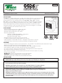
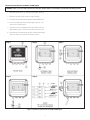
Figure 1
Standard ange model: 0026e-F2
Certified to
NSF/ANSI 61 & 372

-2-
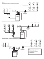
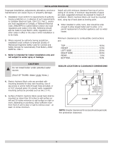
Figure 2:
KEY:
V1, V2,V3 = SHUT-OFF ISOLATION VALVE
P = TACO 0026e CIRCULATOR
FF = FAST FILL BOILER FEED VALVE
PV4 = PURGE VALVE
FC = FLOW CHECK VALVE
MOD CON
BOILER
ZONE 1 ZONE 2 ZONE 3
ZONE 1 ZONE 2 ZONE 3
ZONE 1 ZONE 2 ZONE 3
FC FC FC
FC FC FC
FC FC FC
ZONE 1 ZONE 2 ZONE 3
ZONE 1 ZONE 2 ZONE 3
FCFC - Optional Location FC FC
ZONE 1 ZONE 2 ZONE 3
FCFC - Optional Location FC FC
V3V3V3
V2V2V2
PPP
EXPANSION
TANK
V1
V1
PV4 P
EXPANSION
TANK
BOILER
EXPANSION
TANK
BOILER
V3
V2
P
V3
V2
P
V3
V2
P
V3
V2
P
V3
V2
P
V3
V2
P
V1
PV4
V1
Figure 2
PREFERRED PIPING FOR CIRCULATORS ON BOILER SUPPLY
PREFERRED PIPING FOR CIRCULATORS ON BOILER RETURN
PREFERRED PRIMARY / SECONDARY PIPING FOR CIRCULATORS ON BOILER SUPPLY

-3-
F
PREFERRED PIPING FOR ZONE VALVES ON BOILER SUPPLY
PREFERRED PRIMARY / SECONDARY PIPING FOR ZONE VALVES ON BOILER SUPPLY
ALTERNATE PIPING FOR ZONE VALVES ON BOILER RETURN
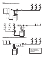
igure 3:
ZONE 1 ZONE 2 ZONE 3
ZONE 1 ZONE 2 ZONE 3
ZONE 1 ZONE 2 ZONE 3 ZONE 1 ZONE 2 ZONE 3
KEY:
V1, V2,V3 = SHUT-OFF ISOLATION VALVE
P = TACO 0026e CIRCULATOR
FF = FAST FILL BOILER FEED VALVE
PV4 = PURGE VALVE
ZV = ZONE VALVE
MOD CON
BOILER
EXPANSION
TANK
EXPANSION
TANK
BOILER
EXPANSION
TANK
BOILER
Figure 3
PREFERRED PIPING FOR ZONE VALVES ON BOILER SUPPLY
ALTERNATE PIPING FOR ZONE VALVES ON BOILER RETURN
PREFERRED PRIMARY / SECONDARY PIPING FOR ZONE VALVES ON BOILER SUPPLY

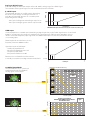
1. Location: The circulator can be installed on the supply or return side of the boiler but for best system
performance, it should always pump away from the expansion tank. See piping diagrams in Figure 2 & Figure 3.
NOTE: Two shorter 1-1/4” x 7/16” ange bolts are provided with the circulator to
use on the discharge ange to prevent interference with the circulator casing.
CAUTION: Do not use at rubber gaskets. Only use O-ring gaskets provided or leaks may result. Warranty will be void.
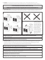
2. Mounting position: Circulator must be mounted with the motor in the horizontal position. See Figure 4 & Figure 5
below for acceptable and unacceptable motor mounting orientations. See Figure 6 for Rotating Control Cover.
CAUTION: To reduce the possibility of noise transmission, be sure to add vibration dampeners to piping when mounting
circulator to wall or oor joists.
ATTENTION : Pour réduire la possibilité de transmission de bruit, veillez à ajouter des amortisseurs de vibration à
la tuyauterie lors du montage du circulateur sur des chevêtres de mur ou de plancher.
3. Filling the system: Fill the system with tap water or a maximum of 50% propylene-glycol and water solution.
The system must be lled before operating the circulator. The bearings are water lubricated and should not
be allowed to operate dry. Filling the system will result in immediate lubrication of the bearings. It is always
good practice to ush a new system of foreign matter before starting the circulator.
WARNING: Risk of electric shock. To reduce the risk of electric shock, be certain that it is connected only to a properly
grounded, grounding-type receptacle. Follow all local electrical and plumbing codes.
AVERTISSEMENT : Risque de choc électrique. Pour réduire le risque de choc électrique, veillez à ce qu’elle soit raccordée uniquement
à un réceptacle de type mise à la terre proprement mis à la terre. Respectez tous les codes de plomberie et électriques locaux.
WARNING: Use supply wires suitable for 90°C.
AVERTISSEMENT : Employer des ls d’alimentation adeqauts pour 90°C.
WARNING: Disconnect power when servicing.
AVERTISSEMENT : Couper l’alimentation lors de l’entretien.
CAUTION: Use exible conduit only. Not for use with rigid conduit.
ATTENTION : N’utiliser que du conduit exible ; n’est pas fait pour du conduit rigide.
-4-
Figure 4 — Acceptable Mounting Positions
Flow
Flow
Flow
Flow
Figure 6 — Rotating Control Cover
Figure 5 — Unacceptable Mounting Positions
The 0026e is equipped
with a symmetrical control
cover connected to the
pump with a ribbon cable.
The cover can be removed,
rotated and repositioned
for best viewing and user
operation. It allows the
installer to mount the
circulator casing in any ow
direction, then rotate the
cover to the upright position.
Remove the 4 cover screws,
rotate cover to upright
position, reattach cover
with 4 screws.

-5-
NEUTRAL
LINE
WIRING DIAGRAM
Removable
Green
Terminal
Plug
Terminal
Screws
GROUND
GNL
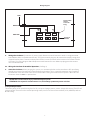
4. Wiring the circulator:
Disconnect AC power supply. Remove terminal box cover. Attach a wiring connector
into knockout hole. Use exible conduit only. The green terminal plug may be removed to simplify wiring, then
snapped back in place. Connect Line/Hot power to the L terminal, Neutral to the N terminal and Ground to the
G terminal. See wiring diagram above. Replace terminal box cover. Insert rubber cap plug provided to cover
unused knockout hole.
4a. Wiring the circulator for 0-10V DC Operation: (See Page 9)
5. Start the circulator: When purging the system, it is recommended to run the circulator at full speed long
enough to remove all remaining air from the bearing chamber. This is especially important when installing
the circulator in the o-season. Turn the dial to the HIGH setting for maximum xed speed. A blue LED will
illuminate when the 0026e is powered on.
CAUTION: Never run the circulator dry or permanent damage may result.
ATTENTION: Ne laissez jamais le circulateur tourner à sec, des dommages permanents peuvent en résulter.
Full Speed Operation:
To run the pump at full speed during the fast ll, start-up and purge process, rotate dial to HIGH setting. The LED will
change to blue. To return to the normal operating mode, turn dial to desired activeADAPT, LOW, MEDIUM, HIGH or
0-10V setting.
Wiring Diagram

-6-
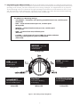
6. Programming your 0026e circulator: Modify the performance of the circulator as needed by rotating the dial
using a at screwdriver. When the circulator is powered on, the LED will illuminate and change color based on the
operating mode selected. The LED will ash each time a setting is changed. See diagram below to set pump for
desired operating mode. The selection of the right operating curve depends on the characteristics of the system
and the actual ow / head requirements. See Pump Curves on pages 7, 8 & 10 to determine the best operating
mode for the system. See cross-reference replacement chart on back page.
The 0026e has 5 Operating Settings:
• activeADAPT — Automatic, self-adjusting, proportional pressure, variable speed.
(Violet LED)
• LOW — 8 feet of head constant pressure, variable speed.
(Orange LED)
• MEDIUM — 16 feet of head constant pressure, variable speed.
(Orange LED)
• HIGH — 26 feet of head max, full xed speed.
(Blue LED)
• 0-10V DC — Analog external input or PWM pulse width modulation
input from building control system, variable speed.
(Yellow LED)
Violet LED
Orange LED
Yellow LED
MEDIUM
– 16 ft. Head
Constant Pressure
Variable Speed
Orange LED
HIGH
– 26 ft. Head
Fixed Speed
White LED
SureStart®
Automatic unblocking
& air purging
0-10V Analog Input
Variable Speed
LOW
– 8 ft. Head
Constant Pressure
Variable Speed
activeADAPT®
Self-adjusting Proportional
Pressure Variable Speed
Blue LED
®
Figure 7 - Dial Settings & Operating Modes

-7-
4 6 820
0
2
4
6
8
10
12
14
16
18
20
22
24
26
28
10 12 14 16 18 20 22 24 26 50
Flow Rate Q [GPM]
28 30 32 34 36 38 40 42 44 46 48
Head [ft.]
MEDIUM
LOW
Head = 8 ft.
Head = 16 ft.
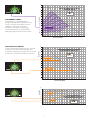
0026e High-Eciency Circulator
Constant Pressure Curves
Orange LED
C
20
0
20
Flow Rate Q [GPM]
Power [W]
4 6 8 10 12 14 16 18 20 22 24 26 28 30 32 34 36 38 40 42 44 46 48 50
40
60
80
100
120
140
MEDIUM
LOW
Power Consumption
0026e High-Eciency Circulator
Constant Pressure Curves
Orange LED
C
420 8 10 12 14 16 18 20 22 24 26 28 30 32 34 36 38 5040 42 44 46 48
Flow Rate Q [GPM]
0
4
6
2
8
10
12
14
16
18
20
22
24
26
28
Head [ft.]
6
0026e High-Eciency Circulator
activeADAPT Range
Purple LED
activeADAPT
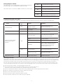
activeADAPT™ Mode:
activeADAPT is an operating mode
designed for constant circulation systems.
On this setting, the circulator will sense
changes in system ow and head
conditions and adjust the operating
curve automatically. See activeADAPT
operating range in the chart to the right.
Constant Pressure Mode:
At Low setting the circulator will vary speed to
maintain 8 feet of head constant pressure.
At Medium setting the circulator will vary speed
to maintain 16 feet of head constant pressure.

-8-
2 4 6 8 10 12 14 16 18 20 22 24 26 28 30 32 34 36 38 40 42 44 46 48 500
0
20
40
60
80
100
120
140
Flow Rate Q [GPM]
Power (W)
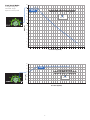
HIGH
Power Consumption
0026e High-Eciency Circulator
Maximum Curve - Fixed Speed
Blue LED
20
Flow Rate Q [GPM]
0
2
4
6
8
10
12
Head [ft.]
4 6 8 10 12 14 16 18 20 22 24 26 28 30 32 34 36 38 40 42 44 46 48 50
14
16
18
20
22
24
26
28
HIGH
Head = 26 ft.
0026e High-Eciency Circulator
Maximum Curve - Fixed Speed
Blue LED
Fixed Speed Mode:
At High setting the
circulator always
operates at full speed.

-9-
External connection for 0-10V DC / PWM signal
WARNING: If there is a need to make external connection (PLC / Pump Controller) it is mandatory to perform the following operations.
1. Remove the 4 screws (1) to open the upper shell (2).
2. Remove the cap (3) for external signal wiring.
3. Disconnect the connector (4) from control board (5).
4. Insert the cable (6) into the cable gland M12x1.5 (7)
and screw it to the cover.
5. Strip the wires (5 mmMIN,) and insert them into the
connector (4), then secure them with the screws (8).
6. Re-connect the connector (4) to the electronic board,
close the cover and secure it with the screws
Figure 8 - External connection for 0-10V DC / PWM signal
Step 1
Step 4
Step 2
Step 5
Step 3
Step 6

Analog or Digital Input
In “0-10V” mode, the circulator accepts either a 0-10VDC voltage signal or a PWM signal.
The selection of the type of signal is made automatically by the circulator.
0-10VDC Input
The circulator operates at variable speed depending
on the DC input voltage. At voltages between 2 V
and 10 V, the circulator operates at a variable speed
depending on the voltage:
- Max. Speed voltage not exceeding or equal to 1V
- Max. Speed voltages greater than or equal to 10V
PWM (Pulse Width Modulation)
2V 4V
6V
8V
10V
0
140
100
120
80
40
20
60
2
04 6 8 10 12 14 16 18 20 22 24 26 28 30 32 34 36 38 40 42 44 46 48 50
Head [ft.]
0
2
4
6
8
10
12
14
16
18
20
22
24
26
28
0-10V
0-10V
Power (W)
2 4 6 8 10 12 14 16 18 20 22 24 26 28 30 32 34 36 38 40 42 44 46 48 50
0
Flow Rate Q [GPM]
Flow Rate Q [GPM]
0026e High-Eciency Circulator
0-10V DC Performance Curves
Power Consumption
0026e High-Eciency Circulator
0-10V DC Curves
YELLOW LED
YELLOW LED
10V
8V
6V
4V
2V
100%
75%
50%
25%
0%
-10-
10V2V1V0.5V
MIN
MAX
SPEED
Input Voltage
0-10V DC Input Mode:
The circulator will vary its speed and
performance based on a 0-10V DC
analog signal external input.
PWM (Pulse Width Modulation)
2V 4V
6V
8V
10V
0
140
100
120
80
40
20
60
2
04 6 8 10 12 14 16 18 20 22 24 26 28 30 32 34 36 38 40 42 44 46 48 50
Head [ft.]
0
2
4
6
8
10
12
14
16
18
20
22
24
26
28
0-10V
0-10V
Power (W)
2 4 6 8 10 12 14 16 18 20 22 24 26 28 30 32 34 36 38 40 42 44 46 48 50
0
Flow Rate Q [GPM]
Flow Rate Q [GPM]
0026e High-Eciency Circulator
0-10V DC Performance Curves
Power Consumption
0026e High-Eciency Circulator
0-10V DC Curves
YELLOW LED
YELLOW LED
10V
8V
6V
4V
2V
100%
75%
50%
25%
0%
IMPORTANT: If the input remains disconnected, the circulator runs at max. speed
PWM Input
Circulator operates at variable speed according to digital input duty cycle. PWM digital input is shared with
0-10V DC analog input, the pump will automatically switch between dierent input protocols when it
detects a constant frequency input signal. 0% and 100% PWM inputs are not valid and will be treated
as an analog input.
PWM amplitude must be from 5 to 12V,
frequency between 200Hz to 5kHz
Operations based on PWM input:
- Standby for PWM below 5%
- Min speed for PWM between 9-16%
- Half speed for 50% PWM
- Max speed for PWM in over 90%
Between 5% to 9% PWM the circulator remains
in standby or run mode according to minimum threshold.
90%
invalid
invalid
5% 9% 16%
0%
100%
SPEED
PWM input
Standby
-11-

Troubleshooting the error codes:
Listed below are potential diagnostic error codes which will appear on the LED display in case of a malfunction.
Unlocking Procedure: A red LED indicates the circulator is locked or sticking. Disconnect and connect power supply to start the
automatic release process. The circulator makes 100 attempts to restart (process lasts approximately 15 minutes). Every restart is
signaled by a short white ash of the LED. If the locking is not removed through the automatic release process after 100 attempts
to restart the circulator, it goes into standby and the LED remains red. In this case follow the manual procedure described in
the next steps: during any attempt, the red LED keeps blinking; after that the circulator tries again to start. If the locking is not
removed through the automatic release process (the warning light returns to red), perform the manual steps described below.
1. Disconnect power supply - the warning light switches o.
2. Close both isolating valves and allow cooling. If there are no shut-o devices,
drain the system so that the uid level is beneath that of the circulator.
3. Loosen 4 motor bolts. Remove motor from casing. Carefully pull the rotor/impeller from the motor.
4. Remove impurities and deposits from the impeller and casing.
5. Reinsert the rotor/impeller into the motor.
6. Connect power supply. Check for impeller rotation.
7. If the circulator still doesn’t run it will need to be replaced.
FAULTS CONTROL
PANEL CAUSE SEIDEMERS
The circulator is noisy
LED on Suction pressure is
insufficient - cavitation
Increase the system suction pressure
within the permissible range.
LED on Presence of foreign bodies
in the impeller Disassemble the motor and clean the impeller.
Loud noises of water circulation Flashing white
LED
Air in the system. Circulator
may be air-bound.
Vent the system.
Repeat fill and purge steps.
Circulator is not running although
the electrical power supply is
switched on
LED off
Lack of power supply Verify voltage value of the electric plant.
Verify the connection of the motor.
Circuit breaker might be
tripped
Check circuit breaker at panel
and reset if necessary.
The circulator is defective Replace the circulator.
Overheating
Let the circulator cool down for some minutes.
Then try to restart it. Verify that the water
and ambient temperature are within the
indicated temperature ranges.
LED red The rotor is blocked Disassemble the motor and clean the impeller.
See unlocking procedure below.
Insufficient supply voltage Verify that the power supply matches
the data on the name plate.
Building does not get warm LED on System may be air-bound Vent system.
Repeat fill and purge steps.
Analog Output 0-10V DC
The circulator has an analog output signal feature to indicate
the operating status and the presence of any errors.
0V Circulator o, not powered
2V Circulator powered in standby
4V Circulator on and running
6V Warning presence (overheating, air)
10V Alarm presence (Circulator blocked,
under voltage, over temperature)
Note: When input is unconnected 0026e circulator runs at full speed.
-11-

LIMITED WARRANTY STATEMENT
Taco, Inc. will repair or replace without charge (at
the company’s option) any Taco product which is
proven defective under normal use within three (3)
years from the date code.
In order to obtain service under this warranty, it
is the responsibility of the purchaser to promptly
notify the local Taco stocking distributor or Taco
in writing and promptly deliver the subject product
or part, delivery prepaid, to the stocking distribu-
tor. For assistance on warranty returns, the pur-
chaser may either contact the local Taco stock-
ing distributor or Taco. If the subject product or
part contains no defect as covered in this war-
ranty, the purchaser will be billed for parts and
labor charges in effect at time of factory exami-
nation and repair.
Any Taco product or part not installed or operated
in conformity with Taco instructions or which has
been subject to misuse, misapplication, the addi-
tion of petroleum-based fluids or certain chemical
additives to the systems, or other abuse, will not
be covered by this warranty.
If in doubt as to whether a particular substance
is suitable for use with a Taco product or part, or
for any application restrictions, consult the
applicable Taco instruction sheets or contact
Taco at (401-942-8000).
Taco reserves the right to provide replacement
products and parts which are substantially similar
in design and functionally equivalent to the
defective product or part. Taco reserves the right
to make changes in details of design, construc-
tion, or arrangement of materials of its products
without notification.
TACO OFFERS THIS WARRANTY IN LIEU OF
ALL OTHER EXPRESS WARRANTIES. ANY
WARRANTY IMPLIED BY LAW INCLUDING
WARRANTIES OF MERCHANTABILITY OR
FITNESS IS IN EFFECT ONLY FOR THE DURA-
TION OF THE EXPRESS WARRANTY SET
FORTH IN THE FIRST PARAGRAPH ABOVE.
THE ABOVE WARRANTIES ARE IN LIEU OF
ALL OTHER WARRANTIES, EXPRESS OR
STATUTORY, OR ANY OTHER WARRANTY
OBLIGATION ON THE PART OF TACO.
TACO WILL NOT BE LIABLE FOR ANY SPECIAL
INCIDENTAL, INDIRECT OR CONSEQUENTIAL
DAMAGES RESULTING FROM THE USE OF
ITS PRODUCTS OR ANY INCIDENTAL COSTS
OF REMOVING OR REPLACING DEFECTIVE
PRODUCTS.
This warranty gives the purchaser specific rights,
and the purchaser may have other rights which
vary from state to state. Some states do not
allow limitations on how long an implied warranty
lasts or on the exclusion of incidental or conse-
quential damages, so these limitations or exclu-
sions may not apply to you.
2021
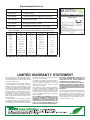
007-007RP Flange Gasket set
198-213RP Casing ‘O’ Ring
198-3396RP Control Panel Cover (0026e Dial Version)
198-3247RP Terminal Box Cover
198-3185RP Wiring Connector (Green)
198-217RP Terminal Box cover screws (5 per bag)
Replacement Parts List
0026e Pump Replacement Cross-Reference (6-1/2” Flange-to-Flange Dimension)
Taco Bell & Gossett Armstrong Grundfos Wilo
2400-10
2400-20
2400-30
2400-40
110
111
112
113
0010
0011
0012
0013
0014
PL 50
PL 30
Series 60 (601)
Series e (e-601)
Series HV
Series PR
Series HV
Series 100
NRF 36
ECOCircXL 20-35
ECOCirc XL 36-45
E 13
E 11
E 10
E 7
S 25
H 32
H 52
H 51
Astro 280
Astro 210
Compass ECM
UP 50-75
UPS 50-44
UP 43-75
UP(S) 26-99
UP 26-96
UP 26-64
UPS 32-80
Magna 32-60
Alpha2 26-99
Stratos:
1.25 x 3 – 25
1.25 x 3 – 20
Top S:
1.25 x 15
1.25 x 25
1.50 x 20
Top Z:
1.5 x 15
1.5 x 20
-12-
LIMITED WARRANTY STATEMENT
Taco, Inc. will repair or replace without charge (at
the company’s option) any Taco product which is
proven defective under normal use within three (3)
years from the date code.
In order to obtain service under this warranty, it
is the responsibility of the purchaser to promptly
notify the local Taco stocking distributor or Taco
in writing and promptly deliver the subject product
or part, delivery prepaid, to the stocking distribu-
tor. For assistance on warranty returns, the pur-
chaser may either contact the local Taco stock-
ing distributor or Taco. If the subject product or
part contains no defect as covered in this war-
ranty, the purchaser will be billed for parts and
labor charges in effect at time of factory exami-
nation and repair.
Any Taco product or part not installed or operated
in conformity with Taco instructions or which has
been subject to misuse, misapplication, the addi-
tion of petroleum-based fluids or certain chemical
additives to the systems, or other abuse, will not
be covered by this warranty.
If in doubt as to whether a particular substance
is suitable for use with a Taco product or part, or
for any application restrictions, consult the
applicable Taco instruction sheets or contact
Taco at (401-942-8000).
Taco reserves the right to provide replacement
products and parts which are substantially similar
in design and functionally equivalent to the
defective product or part. Taco reserves the right
to make changes in details of design, construc-
tion, or arrangement of materials of its products
without notification.
TACO OFFERS THIS WARRANTY IN LIEU OF
ALL OTHER EXPRESS WARRANTIES. ANY
WARRANTY IMPLIED BY LAW INCLUDING
WARRANTIES OF MERCHANTABILITY OR
FITNESS IS IN EFFECT ONLY FOR THE DURA-
TION OF THE EXPRESS WARRANTY SET
FORTH IN THE FIRST PARAGRAPH ABOVE.
THE ABOVE WARRANTIES ARE IN LIEU OF
ALL OTHER WARRANTIES, EXPRESS OR
STATUTORY, OR ANY OTHER WARRANTY
OBLIGATION ON THE PART OF TACO.
TACO WILL NOT BE LIABLE FOR ANY SPECIAL
INCIDENTAL, INDIRECT OR CONSEQUENTIAL
DAMAGES RESULTING FROM THE USE OF
ITS PRODUCTS OR ANY INCIDENTAL COSTS
OF REMOVING OR REPLACING DEFECTIVE
PRODUCTS.
This warranty gives the purchaser specific rights,
and the purchaser may have other rights which
vary from state to state. Some states do not
allow limitations on how long an implied warranty
lasts or on the exclusion of incidental or conse-
quential damages, so these limitations or exclu-
sions may not apply to you.
2021
007-007RP Flange Gasket set
198-213RP Casing ‘O’ Ring
198-3396RP Control Panel Cover (0026e Dial Version)
198-3247RP Terminal Box Cover
198-3185RP Wiring Connector (Green)
198-217RP Terminal Box cover screws (5 per bag)
Replacement Parts List
0026e Pump Replacement Cross-Reference (6-1/2” Flange-to-Flange Dimension)
Taco Bell & Gossett Armstrong Grundfos Wilo
2400-10
2400-20
2400-30
2400-40
110
111
112
113
0010
0011
0012
0013
0014
PL 50
PL 30
Series 60 (601)
Series e (e-601)
Series HV
Series PR
Series HV
Series 100
NRF 36
ECOCircXL 20-35
ECOCirc XL 36-45
E 13
E 11
E 10
E 7
S 25
H 32
H 52
H 51
Astro 280
Astro 210
Compass ECM
UP 50-75
UPS 50-44
UP 43-75
UP(S) 26-99
UP 26-96
UP 26-64
UPS 32-80
Magna 32-60
Alpha2 26-99
Stratos:
1.25 x 3 – 25
1.25 x 3 – 20
Top S:
1.25 x 15
1.25 x 25
1.50 x 20
Top Z:
1.5 x 15
1.5 x 20
-
 1
1
-
 2
2
-
 3
3
-
 4
4
-
 5
5
-
 6
6
-
 7
7
-
 8
8
-
 9
9
-
 10
10
-
 11
11
-
 12
12


Taco Comfort Solutions 0026e ECM High-Efficiency Circulator Pump Manuel utilisateur
- Taper
- Manuel utilisateur
dans d''autres langues
Documents connexes
Autres documents
-
Taco 0034ePlus-F2 High-Efficiency Circulator Pump Manuel utilisateur
-
-
DAB EVOPLUS B 60/240.50 M Instruction For Installation And Maintenance
-
DAB EVOPLUS Manuel utilisateur
-
ACV Prestige 24 / 32 Solo / Excellence (v15) Mode d'emploi
-
U.S. Boiler Company 8B Series spécification
-
-
-
 Argo Technology AT204510B Guide d'installation
