Kichler Lighting 43359CH Manuel utilisateur
- Taper
- Manuel utilisateur

Date Issued: 04/18/16 IS-43359-US
SEE OTHER SIDE FOR SPANISH TRANSLATIONS.
VEA EL OTRO LADO DE TRADUCCIONES AL ESPAÑOL.
We’re here to help 866-558-5706
Hrs: M-F 9am to 5pm EST
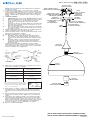
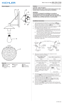
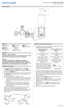
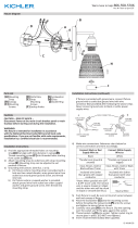
NOTE: Height of fixture must be adjusted before fixture is
mounted to ceiling.
1) To adjust the length of the cord to achieve the desired
height of the mounted fixture: Loosen screw on strain relief
on canopy. Carefully pull cord up into canopy to shorten the
height of fixture or carefully pull cord down to lengthen the
height of fixture. When desired height is achieved, tighten
screw.
2) TURN OFF POWER.
a) IMPORTANT: Before you start, NEVER attempt any work
without shutting off the electricity until the work is done.
b) Go to the main fuse, or circuit breaker, box in your
home. Place the main power switch in the “OFF”
position.
c) Unscrew the fuse(s), or switch “OFF” the circuit breaker
switch(s), that control the power to the fixture or room
that you are working on.
d) Place the wall switch in the “OFF” position. If the fixture
to be replaced has a switch or pull chain, place those in
the “OFF” position.
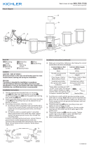
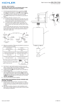
3) Find the appropriate threaded holes on mounting strap. As-
semble mounting screws into threaded holes.
4) Attach mounting strap to outlet box. Mounting strap can be
adjusted to suit position of fixture.
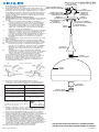
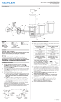
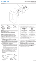
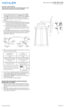
5) Grounding instructions: (See Illus. A or B)
A) On fixtures where mounting strap is provided with a
hole and two raise dimples. Wrap ground wire from
outlet box around green ground screw, and thread into
hole.
B) On fixtures where a cupped washer is provided. Put
ground wire from outlet box under cupped washer
and green ground screw and thread screw into hole in
mounting strap.
If fixture is provided with ground wire. Connect fixture
ground wire to outlet box ground wire with wire connector,
after following the above steps. Never connect ground wire
to black or white power supply wires.
6) Make wire connections. Reference chart below for correct
connections and wire accordingly.
7) Raise fixture to ceiling, carefully passing mounting screws
through holes in canopy. Make sure all wires are inside
canopy and do not get pinched between canopy and ceil-
ing.
8) Slip lockwashers on mounting screws and thread lockup
knobs onto mounting screws. Tighten to secure fixture to
ceiling.
9) Raise glass up to fixture passing socket thru hole in glass
(open end facing downward). Raise spacers inside glass
(larger diameter facing socket). Pass spacer over socket.
Raise socket ring inside glass with bent flange first. Thread
socket ring on socket carefully without cross threading
threads . Tighten to secure. DO NOT over-tighten.
10) Insert recommended bulb(s).
GREEN GROUND
SCREW
CUPPED
WASHER
OUTLET BOX
GROUND
FIXTURE
GROUND
DIMPLES
WIRE CONNECTOR
OUTLET BOX
GROUND
GREEN GROUND
SCREW
FIXTURE
GROUND
A
B
Connect Black or
Red Supply Wire to:
Connect
White Supply Wire to:
Black White
*Parallel cord (round & smooth) *Parallel cord (square & ridged)
Clear, Brown, Gold or Black
without tracer
Clear, Brown, Gold or Black
with tracer
Insulated wire (other than green)
with copper conductor
Insulated wire (other than green)
with silver conductor
*Note: When parallel wires (SPT I & SPT II)
are used. The neutral wire is square shaped
or ridged and the other wire will be round in
shape or smooth (see illus.)
Neutral Wire
OUTLET BOX
CAJA DE SALIDA
STRAP
MOUNTING SCREW(S)
CORREA DE
TORNILLO
DE MONTAJE
CANOPY
ESCUDETE
WIRE CONNECTOR(S)
CONECTOR DE CABLE(S)
MOUNTING STRAP
CORREA DE MONTAJE
MOUNTING SCREW
TORNILLO
DE MONTAJE
LOCKWASHER(S)
ARANDELA
DE SEGURIDAD
LOCK-UP KNOB(S)
PERILLA DE BLOQUEO(S)
STRAIN RELIEF
ALIVIO DE TENSIÓN
CORD
CABLE
FIXTURE
ARTIFACTO
SOCKET
TOMA DE CORRIENTE
GLASS
VIDRIO
SPACER
ESPACIADOR
SOCKET RING
ANILLO DE ZÓCALO

Date Issued: 04/18/16 IS-43359-US
SEE OTHER SIDE FOR ENGLISH TRANSLATIONS.
VEA EL OTRO LADO DE TRADUCCIONES AL INGLÉS.
We’re here to help 866-558-5706
Hrs: M-F 9am to 5pm EST
OUTLET BOX
CAJA DE SALIDA
STRAP
MOUNTING SCREW(S)
CORREA DE
TORNILLO
DE MONTAJE
CANOPY
ESCUDETE
WIRE CONNECTOR(S)
CONECTOR DE CABLE(S)
MOUNTING STRAP
CORREA DE MONTAJE
MOUNTING SCREW
TORNILLO
DE MONTAJE
LOCKWASHER(S)
ARANDELA
DE SEGURIDAD
LOCK-UP KNOB(S)
PERILLA DE BLOQUEO(S)
STRAIN RELIEF
ALIVIO DE TENSIÓN
CORD
CABLE
FIXTURE
ARTIFACTO
SOCKET
TOMA DE CORRIENTE
GLASS
VIDRIO
SPACER
ESPACIADOR
SOCKET RING
ANILLO DE ZÓCALO
Nota: Altura de la luminaria debe ajustarse antes de acceso-
rio está montado en el techo.
1) Para ajustar el largo del cordón para lograr la altura de-
seada del artefacto montado: Afloje el tornillo en el alivio de
la tensión en el escudete. Jale cuidadosamente el cordón
hacia arriba al escudete para acortar la altura del artefacto,
o jale cuidadosamente el cordón hacia abajo para alargar
la altura del artefacto. Cuando se logra la altura deseada,
apriete el tornillo.
2) APAGUE LA ALIMENTACIÓN ELÉCTRICA.
IMPORTANTE: Antes de comenzar, NUNCA trate de trabajar
sin antes desconectar la corriente hasta que el trabajo se
termine.
a) Vaya a la caja principal de fusibles, o interruptor o
caja de circuitos de su casa. Coloque el interruptor de
la corriente principal en posición de apagado “OFF”.
b) Desatornille el (los) fusible (s), o coloque el interruptor
o interruptores del breaker en posición de apagado
“OFF”, que controla (n) la corriente hacia el artefacto o
habitación donde está trabajando.
c) Coloque el interruptor de pared en posición de apagado
“OFF”. Si el artefacto que se va a reemplazar tiene un
interruptor o cadena que se jala, colóquelos en la
posición de apagado “OFF”.11) Encuentre los agujeros
roscados apropiados en la abrazadera de montaje.
Ensamble los tornillos de montaje en los agujeros
roscados.
3) Enrosque un tubo roscado pequeño en el extremo de cada
anillo pequeño.
4) Pase el alambre del artefacto a través del primer anillo.
Enrosque el primer anillo en el extremo del último vástago.
5) Instrucciones para poner a tierra: (Ver Ilustraciones A o B).
A) En artefactos donde se suministra la abrazadera de
montaje con un agujero y dos depresiones onduladas.
Envuelva el conductor de tierra de la caja de salida
alrededor del tornillo de tierra verde y atornille en el
agujero.
B) En artefactos donde se suministra una arandela
cóncava. Fije el conductor de tierra de la caja de salida
debajo de la arandela cóncava y el tornillo de tierra
verde y enrosque en la abrazadera de montaje.
Si se suministra el artefacto con conductor de tierra.
Conecte el conductor de tierra del artefacto al conductor
de tierra de la caja de salida con conector de tierra
después de seguir los pasos anteriores. Nunca conecte
el conductor de tierra a los alambres de alimentación
eléctrica negros o blancos.
6) Haga las conexiones de alambres (No se provee
conectores). Vea la tabla de referencia de abajo para las
conexiones correctas y los alambres correspondientes.
7) Empuje el artefacto al techo, pasando cuidadosamente los
tornillos de montaje a través de los agujeros en el escudete.
Asegúrese de que todos los cables estén dentro del escu-
dete y que no se pellizquen entre el escudete y el techo.
8) Deslice las arandelas de seguridad sobre los tornillos de
montaje. Enrosque las perillas de sujeción en los tornillos de
montaje y apriete para asegurar el artefacto al techo.
9) Suba el vidrio hasta el artefacto pasando el casquillo a
través del agujero en el vidrio (extremo abierto mirando
hacia abajo). Suba los separadores dentro del vidrio (diá-
metro mayor mirando al casquillo). Pase el separador sobre
el casquillo. Suba el anillo del casquillo dentro del vidrio
con el reborde curvado primero. Enrosque cuidadosamente
el anillo del casquillo en el casquillo sin dañar las roscas.
Apriete para asegurar. NO apriete demasiado.
10) Inserte las bombillas (focos) recomendadas.
Connect Black or
Red Supply Wire to:
Connect
White Supply Wire to:
Black White
*Parallel cord (round & smooth) *Parallel cord (square & ridged)
Clear, Brown, Gold or Black
without tracer
Clear, Brown, Gold or Black
with tracer
Insulated wire (other than green)
with copper conductor
Insulated wire (other than green)
with silver conductor
*Note: When parallel wires (SPT I & SPT II)
are used. The neutral wire is square shaped
or ridged and the other wire will be round in
shape or smooth (see illus.)
Neutral Wire
ARANDELA
CONCAVA
TIERRA DE LA
CAJA DE SALIDA
TORNILLO DE TIERRA,
VERDE
DEPRESIONES
TIERRA
ARTEFACTO
CONECTOR DE ALAMBRE
TIERRA DE LA
CAJA DE SALIDA
TORNILLO DE TIERRA,
VERDE
TIERRA
ARTEFACTO
A
B

Date Issued: 04/18/16 IS-43359-CB
INSTRUCTIONS
For Assembling and Installing Fixtures in Canada
Pour L’assemblage et L’installation Au Canada
We’re here to help 866-558-5706
Hrs: M-F 9am to 5pm EST
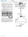
NOTE: Height of fixture must be adjusted before fixture is
mounted to ceiling.
1) To adjust the length of the cord to achieve the desired
height of the mounted fixture: Loosen screw on strain relief
on canopy. Carefully pull cord up into canopy to shorten the
height of fixture or carefully pull cord down to lengthen the
height of fixture. When desired height is achieved, tighten
screw.
2) TURN OFF POWER.
a) IMPORTANT: Before you start, NEVER attempt any work
without shutting off the electricity until the work is done.
b) Go to the main fuse, or circuit breaker, box in your
home. Place the main power switch in the “OFF”
position.
c) Unscrew the fuse(s), or switch “OFF” the circuit breaker
switch(s), that control the power to the fixture or room
that you are working on.
d) Place the wall switch in the “OFF” position. If the fixture
to be replaced has a switch or pull chain, place those in
the “OFF” position.
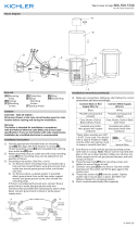
3) Find the appropriate threaded holes on mounting strap. As-
semble mounting screws into threaded holes.
4) Attach mounting strap to outlet box. Mounting strap can be
adjusted to suit position of fixture.
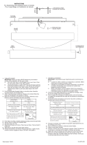
5) Make wire connections. Reference chart below for correct
connections and wire accordingly.
6) Raise fixture to ceiling, carefully passing mounting screws
through holes in canopy. Make sure all wires are inside
canopy and do not get pinched between canopy and
ceiling.
7) Slip lockwashers on mounting screws and thread lockup
knobs onto mounting screws. Tighten to secure fixture to
ceiling.
8) Raise glass up to fixture passing socket thru hole in glass
(open end facing downward). Raise spacers inside glass
(larger diameter facing socket). Pass spacer over socket.
Raise socket ring inside glass with bent flange first. Thread
socket ring on socket carefully without cross threading
threads . Tighten to secure. DO NOT over-tighten.
9) Insert recommended bulb(s).
Connect Black or
Red Supply Wire to:
Connect
White Supply Wire to:
Black White
*Parallel cord (round & smooth)
*Parallel cord (square & ridged)
Clear, Brown, Gold or Black
without tracer
Clear, Brown, Gold or Black
with tracer
Insulated wire (other than green)
with copper conductor
Insulated wire (other than green)
with silver conductor
*Note: When parallel wires (SPT I & SPT II)
are used. The neutral wire is square shaped
or ridged and the other wire will be round in
shape or smooth (see illus.)
Neutral Wire
OUTLET BOX
BOÎTE DE SORTIE
STRAP
MOUNTING SCREW(S)
VIS DE
FIXATION
DE SANGLE(S)
CANOPY
COUVERCLE
WIRE CONNECTOR(S)
CONNECTEUR DE FIL(S)
MOUNTING STRAP
SANGLE DE FIXATION
MOUNTING SCREW
VIS DE MONTAGE
LOCKWASHER(S)
RONDELLE
DE BLOCAGE
LOCK-UP KNOB(S)
BOUTON
DE VERROUILLAGE(S)
STRAIN RELIEF
DÉCHARGE
DE TRACTION
CORD
CORDON
FIXTURE
LUMINAIRE
SOCKET
PRISE DE COURANT
GLASS
VERRE
SPACER
ENTRETOISE
SOCKET RING
ANNEAU DE DOUILLE

Date Issued: 04/18/16 IS-43359-CB
SEE OTHER SIDE FOR ENGLISH TRANSLATIONS.
VOIR L’AUTRE CÔTÉ DES TRADUCTIONS EN ANGLAIS.
We’re here to help 866-558-5706
Hrs: M-F 9am to 5pm EST
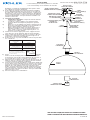
Remarque : La hauteur du gabarit doit être ajustée avant
que l’appareil est monté au plafond.
1) Pour régler la longueur du cordon à la hauteur souhaitée
pour le luminaire installé. Desserrer la vis sur le réducteur
de tension du cache. Tirer soigneusement le cordon vers le
haut dans le cache pour raccourcir la hauteur du luminaire
ou tirer soigneusement le cordon vers le bas pour allonger
la hauteur du luminaire. Lorsque la hauteur souhaitée est
atteinte, serrer la vis.
2) COUPER LE COURANT
IMPORTANT: TOUJOURS couper l’électricité avant de
commencer le travail.
a) Localiser le coffret à fusibles ou le disjoncteur du
domicile. Mettre l’interrupteur principal en position
d’Arrêt.
b) Dévisser le ou les fusibles (ou mettre le disjoncteur sur
Arrêt) qui contrôlent l’alimentation vers le luminaire ou
la pièce dans laquelle le travail est effectué.
c) Mettre l’interrupteur mural en position d’Arrêt. Si le l
uminaire à remplacer est doté d’un interrupteur ou
d’une chaîne connectée à l‘interrupteur, placer ces
éléments en position d’Arrêt.
3) Trouver les trous letés appropriés sur le support de mon-
tage. Visser les vis de montage dans les trous taraudés.
4) Fixer le support de montage sur la bo te à prises. (Vis non
fournies). Le support de montage peut être réglé a n de
positionner correctement le luminaire.
5) Connecter les ls. Se porter au tableau ci-dessous pour faire
les connexions.
6) Pousser le luminaire vers le plafond en passant soigneuse-
ment les vis de montage par les trous dans le couvercle.
S’assurer que tous les fils sont à l’intérieur du couvercle et
ne sont pas pincés entre le couvercle et le plafond.
7) Faire passer les rondelles de blocage par-dessus les vis de
fixation. Visser les boules de blocage sur la vis de fixation
et serrer pour fixer le luminaire au plafond.
8) Soulever le verre jusqu’au luminaire en passant la douille par
le trou dans le verre (extrémité ouverte orientée vers le bas).
Soulever les entretoises à l’intérieur du verre (le plus grand
diamètre face à la douille). Passer une entretoise sur la
douille. Soulever l’anneau de la douille à l’intérieur du verre
avec la bride pliée en premier. Visser l’anneau de la douille
soigneusement sans fausser les filets. Serrer pour fixer. NE
PAS serrer avec excès.
9) Visser les ampoules recommandées.
Connecter le fil noir ou
rouge de la boite
Connecter le fil blanc de la boîte
A Noir A Blanc
*Au cordon parallèle (rond et lisse)
*Au cordon parallele (à angles droits el strié)
Au bransparent, doré, marron, ou
noir sans fil distinctif
Au transparent, doré, marron, ou
noir avec un til distinctif
Fil isolé (sauf fil vert) avec
conducteur en cuivre
Fil isolé (sauf fil vert) avec
conducteur en argent
*Remarque: Avec emploi d’un fil paralléle
(SPT I et SPT II). Le fil neutre est á angles
droits ou strié et l’autre fil doit étre rond ou
lisse (Voir le schéma).
Fil Neutre
INSTRUCTIONS
For Assembling and Installing Fixtures in Canada
Pour L’assemblage et L’installation Au Canada
OUTLET BOX
BOÎTE DE SORTIE
STRAP
MOUNTING SCREW(S)
VIS DE
FIXATION
DE SANGLE(S)
CANOPY
COUVERCLE
WIRE CONNECTOR(S)
CONNECTEUR DE FIL(S)
MOUNTING STRAP
SANGLE DE FIXATION
MOUNTING SCREW
VIS DE MONTAGE
LOCKWASHER(S)
RONDELLE
DE BLOCAGE
LOCK-UP KNOB(S)
BOUTON
DE VERROUILLAGE(S)
STRAIN RELIEF
DÉCHARGE
DE TRACTION
CORD
CORDON
FIXTURE
LUMINAIRE
SOCKET
PRISE DE COURANT
GLASS
VERRE
SPACER
ENTRETOISE
SOCKET RING
ANNEAU DE DOUILLE
-
 1
1
-
 2
2
-
 3
3
-
 4
4


Kichler Lighting 43359CH Manuel utilisateur
- Taper
- Manuel utilisateur
dans d''autres langues
Documents connexes
-
 Kichler Lighting 44271PN Manuel utilisateur
-
 Kichler Lighting 45949CH Manuel utilisateur
-
 Kichler Lighting 45948CH Manuel utilisateur
-
 Kichler Lighting 45947CH Manuel utilisateur
-
 Kichler Lighting 45946CH Manuel utilisateur
-
 Kichler Lighting 49865WZC Manuel utilisateur
-
 Kichler Lighting 44218CLP Manuel utilisateur
-
 Kichler Lighting 42275NI Manuel utilisateur
-
 Kichler Lighting 49917BK Manuel utilisateur
-
 Kichler Lighting 44148OZ Manuel utilisateur


