Progress Lighting 93138704 C Guide d'installation
- Catégorie
- Ventilateurs ménagers
- Taper
- Guide d'installation

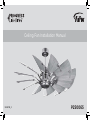
Ceiling Fan Installation Manual
P250065
93138704_C

Date Pu rchased
Store Purchased
Model No.
Serial No.
Ven d o r No.
UPC
109226
Limited Lifetime Warranty
Progress Lighting fan motors are warranted to the original purchaser to be free of electrical and/or mechanical defects for so
long as the original purchaser owns the fan. Pull chain switches, reverse switches, capacitors and metal finishes are warranted to
be free from defects in materials or workmanship for a period of 1 year from the date of purchase. Warping of wooden or plastic
blades is not covered by this warranty nor is corrosion and/or deterioration of any finishes for fans installed within ten miles of
any sea coast. Extended warranties for ENERGY STAR® qualified products may apply.
Progress Lighting ceiling fans with built-in LED light sources, when properly installed and under normal conditions of use, are
warranted to be free from defects in material and workmanship which cause the light sources to fail to operate in accordance
with the specifications for (i) five (5) years from the date of purchase on the LED Light modules and electrical components for
fans used in single family residences, and (ii) three (3) years from the date of purchase on the LED Light modules and electrical
components for fans used in multi-family or commercial applications. LED bulbs supplied by Progress Lighting carry no
warranty other than manufacturer’s warranty. Non-LED bulbs carry no warranty.
With proof of purchase, the original purchaser may return the defective fan to the place of purchase during the first 30 days for
replacement. After 30 days, the original purchaser MUST contact Progress Lighting at (864) 678-1000 for repair or replacement
which shall be determined in Progress Lighting’s sole discretion and shall be purchaser’s sole and exclusive remedy.
Labor and Shipping Excluded. This warranty does not cover any costs or fees associated with the labor (including, but not
limited to, electrician’s fees) required to install, remove, or replace a fan or any fan parts.
This warranty shall not apply to any loss or damage resulting from (i) normal wear and tear or alteration, misuse, abuse or
neglect, or (ii) improper installation, operation, repair or maintenance by original purchaser or a third party, including without
limitation improper voltage supply or power surge, use of improper parts or accessories, unauthorized repair (made or
attempted) or failure to provide maintenance to the fan.
THE FOREGOING WARRANTIES STATE PROGRESS LIGHTING’S ENTIRE WARRANTY OBLIGATION AND
ORIGINAL PURCHASER’S SOLE AND EXCLUSIVE REMEDY RELATED TO SUCH PRODUCTS. PROGRESS
LIGHTING IS NOT RESPONSIBLE FOR DAMAGES (INCLUDING INDIRECT, SPECIAL, INCIDENTIAL OR
CONSEQUENTIAL), DUE TO PRODUCT FAILURE, WHETHER ARISING OUT OF BREACH OF WARRANTY,
BREACH OF CONTRACT, OR OTHERWISE. THIS WARRANTY IS GIVEN IN LIEU OF ALL OTHER WARRANTIES,
WHETHER EXPRESSED OR IMPLIED, INCLUDING THOSE OF MERCHANTABILITY, FITNESS FOR A PARTICULAR
PURPOSE OR NONINFRINGEMENT.
Some states do not allow limitations on how long an implied warranty lasts or the exclusion or limitations of incidental or
consequential damages, so the above limitations and exclusions may not apply to you. This warranty gives you specific rights
and you may have other rights which vary from state to state.
785247250042
785247250035
785247250059

Table of Contents
Safety Rules.....................................................................................................................................................................................
Unpacking Your Fan .......................................................................................................................................................................
Installing Your Fan .........................................................................................................................................................................
Installing the Decorative Cover .....................................................................................................................................................
Operating Your Transmitter ..........................................................................................................................................................
Care of Your Fan ...........................................................................................................................................................................
Troubleshooting ............................................................................................................................................................................
Specifications ................................................................................................................................................................................
1.
2.
3.
9.
10.
12.
13.
14.

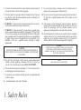
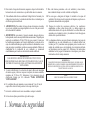
1. Safety Rules
1. To reduce the risk of electric shock, insure electricity has been turned off
at the circuit breaker or fuse box before beginning.
2. All wiring must be in accordance with the National Electrical Code and
local electrical codes. Electrical installation should be performed by a
qualified licensed electrician.
3. WARNING: To reduce the risk of electrical shock and fire, do not use
this fan with any solid-state fan speed control device.
4. WARNING: To reduce the risk of fire, electric shock, or personal injury,
mount to outlet box marked "Acceptable for Fan Support of 15.9 kg (35 lbs.)
Or Less" and use mounting screws provided with the outlet box. Most outlet
boxes commonly used for the support of light fixtures are not acceptable for
fan support and may need to be replaced. Due to the complexity of the
installation of this fan, a qualified licensed electrician is strongly
recommended.
WARNING
TO REDUCE THE RISK OF FIRE, ELECTRIC SHOCK OR PERSONAL
INJURY, MOUNT FAN TO OUTLET BOX MARKED ACCEPTABLE FOR
FAN SUPPORT.
5. The outlet box and support structure must be securely mounted and
capable of reliably supporting a minimum of 35 lbs (15.9 kg) or less.
Use only cUL-listed outlet boxes marked FOR FAN SUPPORT.
6. The fan must be mounted with a minimum of 7 ft (2.1m) clearance from
the trailing edge of the blades to the floor.
7. To operate the reverse function on this fan, press the reversing button while
the fan is running.
8. Avoid placing objects in the path of the blades.
9. To avoid personal injury or damage to the fan and other items, be
cautious when working around or cleaning the fan.
10. Do not use water or detergents when cleaning the fan or fan blades. A
dry dust cloth or lightly dampened cloth will be suitable for most
cleaning.
11. After making electrical connections, spliced conductors should be
turned upward and pushed carefully up into the outlet box. The wires
should be spread apart with the grounded conductor and the
equipment-grounding conductor on one side of the outlet box.
12. Electrical diagrams are for reference only. Light kits that are not packed
with the fan must be cUL Listed and marked suitable for use with the
model fan you are installing. Switches must be cUL General Use
Switches. Refer to the Instructions packaged with the light kits.
NOTE
READ AND SAVE ALL INSTRUCTIONS!
WARNING
TO REDUCE THE RISK OF PERSONAL INJURY, DO NOT BEND THE
BLADE ARMS (ALSO REFERRED TO AS BRACKETS) DURING
ASSEMBLY OR AFTER INSTALLATION. DO NOT INSERT OBJECTS IN
THE PATH OF THE BLADES.

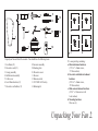
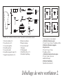
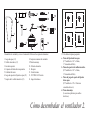
Unpacking Your Fan 2.
15. Loose parts bag containing:
a. Blade attachment hardware
(37 3/16" x 10mm screws,
37 fiber washers)
b. Decorative rod holder attachment
hardware
(25 3/16" x 10mm screws,
25 fiber washers)
c. Blade arms attachment hardware
(25 1/4" x 15mm screws with
lock washers)
d. Mounting hardware
Wire nuts (3)
15
ab
c d
Unpack your fan and check the contents. You should have the following items:
1. Fan blades (12)
2. Decorative rods (12)
3. Canopy assembly
4. Ball/downrod assembly
5. Collar cover
6. Set of blade brackets (12)
7. Decorative rod holders (12)
8. Fan motor assembly
9. Mounting plate
10. Decorative cover
11. Receiver
12. Remote control
13. 12V MN21/A23 battery
14. Balancing kit
4
1
2
39
11
5
10
6
7
812
14
13

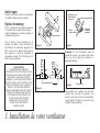
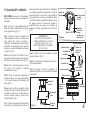
Tools Required
Phillips screw driver, straight slot screw driver,
adjustable wrench, step ladder, and wire cutters.
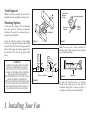
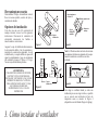
Mounting Options
If there isn't an existing cUL listed mounting
box, then read the following instructions.
Disconnect the power by removing fuses or
turning off circuit breakers.
Secure the outlet box directly to the building
structure. Use appropriate fasteners and building
materials. The outlet box and its support must be
able to fully support the moving weight of the
fan (at least 35 lbs). Do not use plastic outlet
boxes.
Figure 4
Figure 3
Figure 1
Figure 2
Outlet box
Outlet box Outlet box
Note: You may need a longer downrod to
maintain proper blade clearance when installing
on a steep, sloped ceiling.
To hang your fan where there is an existing
fixture but no ceiling joist, you may need an
installation hanger bar as shown in Figure 4
(available at your Progress Lighting Retailer).
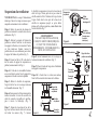
3. Installing Your Fan
WARNING
TO REDUCE THE RISK OF FIRE, ELECTRIC
SHOCK, OR OTHER PERSONAL INJURY,
MOUNT FAN ONLY TO AN OUTLET BOX
MARKED ACCEPTABLE FOR FAN SUPPORT
AND USE THE MOUNTING SCREWS
PROVIDED WITH THE OUTLET BOX. OUTLET
BOXES COMMONLY USED FOR THE
SUPPORT OF LIGHTING FIXTURES MAY NOT
BE ACCEPTABLE FOR FAN SUPPORT AND
MAY NEED TO BE REPLACED. CONSULT A
QUALIFIED ELECTRICIAN IF IN DOUBT.
Angled ceiling
maximum
25 angle
Recessed
outlet box
Provide strong support
Ceiling
hanger
bracket

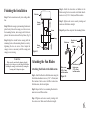
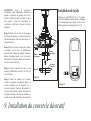
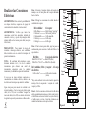
4.
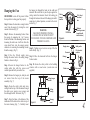
Hanging the Fan
REMEMBER to turn off the power. Follow
the steps below to hang your fan properly:
Step 1. Remove the decorative canopy bottom
cover from the canopy by turning the cover
counter clockwise.(Fig. 5)
Step 2. Remove the mounting bracket from
the canopy by removing the 1 of 2 screws
from the bottom of the mounting bracket and
loosening the other one a half turn from the
screw head. Next, turn the canopy counter
clockwise to removing the mounting bracket
from the canopy. (Fig. 5)
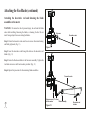
Step 3. Pass the 120-volt supply wires
through the center hole in the ceiling hanger
bracket as shown in Fig. 6.
Step 4. Secure the hanger bracket to the
ceiling outlet box with the screws and
washers provided with your outlet box.
Step 5. Remove the hanger pin, lock pin and
set screws from the top of the motor
assembly. (Fig. 7)
Step 6. Route the safety cable and wires
exiting from the top of the fan motor through
the collar cover, canopy cover, canopy and
then through the ball / downrod. (Fig. 7)
Step 7. Align the holes at the bottom of the
downrod with the holes in the collar on top of
the motor housing (Fig. 7). Carefully insert
the hanger pin through the holes in the collar and
downrod. Be careful not to jam the pin against the
wiring inside the downrod. Insert the locking pin
through the hole near the end of the hanger pin until it
snaps into its locked position, as noted in the circle
inset of Fig. 7.
WARNING
FAILURE TO PROPERLY INSTALL
LOCKING PIN AS NOTED IN STEP 7
COULD RESULT IN FAN LOOSENING AND
POSSIBLY FALLING.
Figure 6
Figure 7
Ceiling
hanger
bracket
Mounting screws
(supplied with
electrical box)
CUL Listed
electrical
box
120V Wires
Washers
Supply wires
Downrod
Hanger pin Lock pin
Set screws
Canopy
Canopy cover
Collar cover
Pin in locked
position
Step 8. Tighten two set screws on top of the fan
motor firmly. (Fig. 7)
Step 9. Place the downrod ball into the hanger
bracket socket.
Step 10. Secure the safety cable to the building
structure with a wood screw. (wood screw not
supplied)
Figure 5
Ceiling hanger
bracket
Ceiling
canopy
Canopy
cover
Safety cable

5.
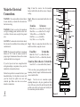
Make the Electrical
Connections
WARNING: To avoid possible electrical shock,
be sure electricity is turned off at the main fuse
box before wiring.
WARNING: Check to see that all connections
are tight, including ground, and that no bare wire
is visible at the wire nuts, except for the ground
wire.
CAUTION: To reduce the risk of electric shock,
this fan must be installed with an isolating wall
control/switch.
NOTE: The fan must be installed at a maximum
distance of 20 ft. from the remote control for
proper signal transmission between the remote
control and the fan's receiving unit.
If you feel you do not have enough electrical
wiring knowledge or experience, have your fan
installed by a licensed electrician.
Follow the steps below to connect the fan to your
household wiring. Use the plastic wire nuts with
your fan. Secure the plastic wire nuts with
electrical tape. Make sure there are no loose
strands or connections.
Figure 8
Step 1. Insert the receiver into the mounting
bracket with the flat side of the receiver facing the
ceiling.
Step 2. Make wire connections from the fan to the
receiver.
From Fan To Receiver
White Wire ---------White Wire "For Light"
Blue Wire ----------Blue Wire "For Light"
Yellow Wire -------Yellow Wire
Red Wire ---------- Red Wire
Grey Wire --------- Grey Wire
Step 3. Make wire connections from the filter to the
outlet box as follows, using the wire nuts.
From Filter To Outlet Box
Black Wire "AC in L" ------Black Wire (Hot)
White Wire "AC in N"------White Wire (Neutral)
From Fan, Filter & Receiver To Outlet Box
Green Wires* ----- Green or Bare Wire (Ground)
*
There are four green grounding leads: from the
mounting bracket, hanger ball/downrod assembly,
receiver and the filter.
Step 4. Turn the wire nut connections upward,
spreading them apart so the green (ground) and white
wires will be on one side of the outlet box and the black
and blue wires will be on the other side. Carefully tuck
the connections up into the outlet box.
White
White
White
Canopy
Black
Black
Black
Filter
Receiver
Outlet Box
White
White
Blue
Blue
Red
Red
Yellow
Yellow
Grey
Grey
Green
Green
Green
Ground conductor
Green
Green

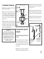
6.
Finishing the Installation
Step 1. Tuck connections neatly into ceiling outlet
box.
Step 2. Slide the canopy up to mounting bracket and
place the key hole on the canopy over the screw on
the mounting bracket, turn canopy until it locks in
place at the narrow section of the key holes. (Fig. 9)
Step 3. Align the circular hole on canopy with the
remaining hole on the mounting bracket, secure by
tightening the two set screws. Note: Adjust the
canopy screws as necessary until the canopy and
canopy cover are snug.
Attaching the Fan Blades
Attaching the blades to the blade arms
Step 1. Attach the blades to the blade arms using the
three blade attachment screws (3/16" x 10mm) and
fiber washers. Start a screw with fiber washer into
the blade arms, but do not tighten.
Step 2. Repeat for the two remaining blade attach-
ment screws and fiber washers.
Step 3. Tighten each screw securely starting with
the center screw. Make sure the blade is straight.
Step 4. Attach the decorative rod holders to the
blades using the two decorative rod holder attach-
ment screws (3/16" x 10mm) and fiber washers.
Step 5. Tighten each screw securely starting and
make sure the blade is straight.
Step 6. Repeat these steps for the remaining blades .
WARNING
Make sure the notch on the hanging bracket
properly sits in the groove in the hanger ball before
attaching the canopy to the bracket by turning the
housing until it drops into place.
Outlet box
Canopy
cover
Canopy
Hanger
bracket
Figure 9
Screws
Figure 10
Blade screws
(3/16" x 10mm)
and fiber washers
Blades
Blade arms
Decorative rod
holders
Decorative rod
holder screws
(3/16" x 10mm)
and fiber washers

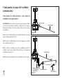
7.
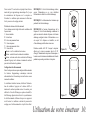
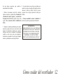
Attaching the Fan Blades (continued)
Attaching the decorative rod and fastening the blade
assemblies to the motor
WARNING: To reduce the risk of personal injury, do not bend the blade
arms while installing, balancing the blades, or cleaning the fan. Do not
insert foreign objects between rotating fan blades.
Step 1. Rotate the decorative rods onto the setscrew on the motor housing
and firmly tightened. (Fig. 11)
Step 2. Insert the decorative rods through the holes on the decorative rod
holder. (Fig. 11)
Step 3. Fasten the blade assemblies to the fan motor assembly. Tighten the
two blade arm screws with lock washers provided. (Fig. 11)
Step 4. Repeat this procedure for the remaining blade assemblies.
Figure 11
Decorative rods
Setscrew
Figure 12
Decorative rods
Decorative rod
holders
Blade assembly
Blade arm screws (1/4" x 15mm)
with fiber washers

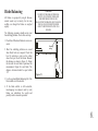
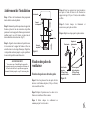
Blade Balancing
All blades are grouped by weight. Because
natural woods very in density, the fan may
wobble even though the blades are weighed
equally.
The following procedure should correct most
fan wobbling problems. Check after each step.
1. Check that all blade and blade arm screws are
secure.
2. Most fan wobbling problems are caused
when blade levels are unequal. Check this
level by selecting a point on the ceiling
above the tip of one of the blades. Measure
this distance as shown in Figure 13. Rotate
the fan until the next blade is positioned for
measurement. Repeat for each blade. The
distance deviation should be equal within
1/8".
3. Use the enclosed Blade Balancing Kit if the
blade wobble is still noticeable.
4. If the blade wobble is still noticeable,
interchanging two adjacent (side by side)
blades can redistribute the weight and
possibly result in smoother operation.
Touching
ceiling
Figure 13
WARNING
TO REDUCE THE RISK OF PERSONAL
INJURY, DO NOT BEND THE BLADE
HOLDERS WHILE INSTALLING,
BALANCING THE BLADES, OR CLEANING
THE FAN. DO NOT INSERT FOREIGN
OBJECTS BETWEEN ROTATING FAN
BLADES.
8.

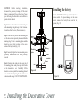
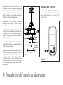
9.
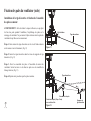
Installing the
Decorative Cover
CAUTION: Before starting installation,
disconnect the power by turning off the circuit
breaker or removing the fuse at fuse box. Turning
power off using the fan switch is not sufficient to
prevent electric shock.
Step 1. Remove the 1 of 3 screws from the posts
of the mounting ring and keep it for future use.
Loosen the other 2 screws. (Do not remove)
Step 2. Place the key holes in the mounting plate
over the two screws previously loosened from the
mounting ring. Turn the mounting plate until the
decorative cover locks in place at the narrow
section of the key holes. (Fig. 14)
Step 3. Securely tighten the two mounting screws
previously loosened and the one previously
removed.
Step 4. Position the notches in the outer rim of
the mounting plate so they line up with the tabs
on the decorative cover. Carefully lift the
decorative cover up inside the mounting plate and
secure it to the fan by turning the decorative cover
clockwise until snug. DO NOT OVERTIGHTEN.
Figure 14
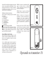
Installing the battery
Install a 12V MN21/A23 battery (included) into the
remote control. To prevent damage to the remote
control, remove the battery if not used for long
periods. (Fig. 15)
Figure 15
Screws
Mounting
ring
Mounting
plate
Tab
Decorative
cover

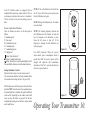
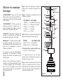
Operating Your Transmitter 10.
Figure 17
Figure 16
Your DC brushless motor is equipped with an
automatically learned type remote control. There is
no frequency switches on the receiver or transmitter.
The fan can start to use once the pairing process is
done.
Remote Control Button Definitions:
These six buttons are used to set the fan speed as
follows:
I = minimum speed
II = low speed
III = medium low speed
IV = medium speed
V = medium high speed
VI = high speed
button: Turns the fan off.
button: Controls fan direction.
button: This button is to control optional light on or off.
Press and hold the button to activate the dimmer function.
Setting the Remote Control
Follow the below steps to set the remote control:
The auto learning function will only mandate within
60 seconds when turning the fan’s AC power ON.
With the fan’s power off, restore power to the fan. Press
and hold “SET” button for about 5 seconds and release.
If optional light kit is installed, the light kit will flash
twice and the signal light on the remote control will
come on when the button is pressed. The fan has
completed the pairing process with the remote control
and is ready for use.
NOTE: If the self calibration test failed, turn
the AC power off; restore power and process
the self calibration test again.
NOTE: During self calibration test, the remote
is non-fuctional.
NOTE: The learning frequency function and
self calibration test will continue to retain the
last set frequency and calibration set even
when the AC power is shut off. If the
frequency is changed the self calibration test
will occur again.
Over 80W protection: When the receiver
detects motor power consumption which is
greater than 80W, the receiver power will be
stopped and operation will immediately
discontinue. Wait for 5 seconds and then turn
the receiver power back on.

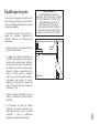
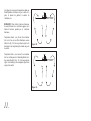
Speed settings for warm or cool weather depend on
factors such as the room size. Ceiling height, number
of fans and so on.
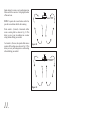
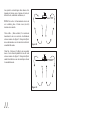
NOTE: To operate the reverse function on this fan,
press the reverse button while the fan is running.
Warm weather - (Forward) A downward airflow
creates a cooling effect as shown in Fig. 18. This
allows you to set your air conditioner on a warmer
setting without affecting your comfort.
Cool weather - (Reverse) An upward airflow moves
warm air off the ceiling area as shown in Fig. 19. This
allows you to set your heating unit on a cooler setting
without affecting your comfort.
Figure 18
Figure 19
11.

Here are some suggestions to help you maintain your
fan
1. Because of the fan's natural movement, some
connections may become loose.
Check the support
connections, brackets, and blade attachments
twice a year.
Make sure they are secure.
(It is not
necessary to remove fan from ceiling.)
2. Clean your fan periodically to help maintain its new
appearance over the years. Use only a soft brush or
lint-free cloth to avoid scratching the finish. The
plating is sealed with a lacquer to minimize
discoloration or tarnishing. Do not use water when
cleaning. This could damage the motor, or the wood,
or possibly cause an electrical shock.
3. You can apply a light coat of furniture polish to the
wood blades for additional protection and enhanced
beauty. Cover small scratches with a light application
of shoe polish.
4.
There is no need to oil your fan.
The motor has
permanently lubricated bearings.
IMPORTANT
MAKE SURE THE POWER IS OFF AT THE
ELECTRICAL PANEL BOX BEFORE YOU
ATTEMPT ANY REPAIRS. REFER TO THE
SECTION "MAKING ELECTRICAL
CONNECTIONS"
Care of Your Fan
12.

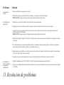
13.
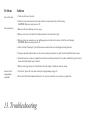
Troubleshooting
Solution
1. Check circuit fuses or breakers.
2. Check line wire connections to the fan and switch wire connections in the switch housing.
CAUTION: Make sure main power is off.
1. Make sure all motor housing screws are snug.
2. Make sure the screws that attach the fan blade bracket to the motor hub is tight.
3. Make sure wire nut connections are not rubbing against each other or the interior wall of the switch housing.
CAUTION: Make sure main power is off.
4. Allow a 24-hour "breaking-in" period. Most noise associated with a new fan disappear during this time.
5. If using an optional light kit, make sure the screws securing the glassware are tight. Check that light bulb is also secure.
6. Some fan motors are sensitive to signals from solid-state variable speed controls. If you have installed this type of control,
choose and install another type of control.
7. Make sure the upper canopy is a short distance from the ceiling. It should not touch the ceiling.
1. Turn the AC power off to fan, and re-do steps for programming on page 10.
2. Do not turn off fan from standard wall switch. Use only our wall switch or your remote to regulate fan.
Problem
Fan will not start.
Fan sounds noisy.
Fan has lost its
programming
repeatedly.

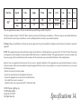
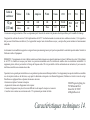
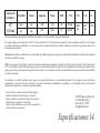
Specifications
14.
29.81
lbs
33.37
lbs
2.54'
Fan Size Speed Volts Amps Watts RPM CFM N.W. G.W. C.F.
52"
Low
High
120
120
These are approximate measures. They do not include Amps and Wattage used by the light kit.
0.08
0.39
3.85
29.66
48
112
2745.38
6296.22
This device complies with part 15 of the FCC Rules. Operation is subject to the following two conditions: (1) This device may not cause harmful interference,
and (2) this device must accept any interference received, including interference that may cause undesired operation.
Warning: Changes or modifications to this unit not expressly approved by the party responsible for compliance could void the user's authority to operate the
equipment.
NOTE: This equipment has been tested and found to comply with the limits for a Class B digital device, pursuant to Part 15 of the FCC Rules. These limits
are designed to provide reasonable protection against harmful interference in a residential installation. This equipment generates, uses and can radiate radio
frequency energy and, if not installed and used in accordance with the instructions, may cause harmful interference to radio communications.
However, there is no guarantee that interference will not occur in a particular installation. If this equipment does cause harmful interference to radio or
television reception, which can be determined by turning the equipment off and on, the user is encouraged to try to correct the interference by one or more of
the following measures:
- Reorient or relocate the receiving antenna.
- Increase the separation between the equipment and receiver.
- Connect the equipment into an outlet on a circuit different from
that to which the receiver is connected.
- Consult the dealer or an experienced radio/TV technician for help.
©2020 Progress Lighting, Inc.
701 Millennium Blvd.,
Greenville, SC 29607
All Rights Reserved

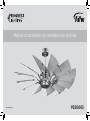
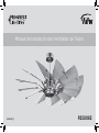
Manuel d’installation du ventilateur de plafond
P250065
93138704_C

Date Purch as ed
Store Purchased
Model No.
Serial No.
Vendor No.
UPC
109226
785247250035
785247250042
785247250059
Limited Lifetime Warranty
Progress Lighting fan motors are warranted to the original purchaser to be free of electrical and/or mechanical defects for so
long as the original purchaser owns the fan. Pull chain switches, reverse switches, capacitors and metal finishes are warranted to
be free from defects in materials or workmanship for a period of 1 year from the date of purchase. Warping of wooden or plastic
blades is not covered by this warranty nor is corrosion and/or deterioration of any finishes for fans installed within ten miles of
any sea coast. Extended warranties for ENERGY STAR® qualified products may apply.
Progress Lighting ceiling fans with built-in LED light sources, when properly installed and under normal conditions of use, are
warranted to be free from defects in material and workmanship which cause the light sources to fail to operate in accordance
with the specifications for (i) five (5) years from the date of purchase on the LED Light modules and electrical components for
fans used in single family residences, and (ii) three (3) years from the date of purchase on the LED Light modules and electrical
components for fans used in multi-family or commercial applications. LED bulbs supplied by Progress Lighting carry no
warranty other than manufacturer’s warranty. Non-LED bulbs carry no warranty.
With proof of purchase, the original purchaser may return the defective fan to the place of purchase during the first 30 days for
replacement. After 30 days, the original purchaser MUST contact Progress Lighting at (864) 678-1000 for repair or replacement
which shall be determined in Progress Lighting’s sole discretion and shall be purchaser’s sole and exclusive remedy.
Labor and Shipping Excluded. This warranty does not cover any costs or fees associated with the labor (including, but not
limited to, electrician’s fees) required to install, remove, or replace a fan or any fan parts.
This warranty shall not apply to any loss or damage resulting from (i) normal wear and tear or alteration, misuse, abuse or
neglect, or (ii) improper installation, operation, repair or maintenance by original purchaser or a third party, including without
limitation improper voltage supply or power surge, use of improper parts or accessories, unauthorized repair (made or
attempted) or failure to provide maintenance to the fan.
THE FOREGOING WARRANTIES STATE PROGRESS LIGHTING’S ENTIRE WARRANTY OBLIGATION AND
ORIGINAL PURCHASER’S SOLE AND EXCLUSIVE REMEDY RELATED TO SUCH PRODUCTS. PROGRESS
LIGHTING IS NOT RESPONSIBLE FOR DAMAGES (INCLUDING INDIRECT, SPECIAL, INCIDENTIAL OR
CONSEQUENTIAL), DUE TO PRODUCT FAILURE, WHETHER ARISING OUT OF BREACH OF WARRANTY,
BREACH OF CONTRACT, OR OTHERWISE. THIS WARRANTY IS GIVEN IN LIEU OF ALL OTHER WARRANTIES,
WHETHER EXPRESSED OR IMPLIED, INCLUDING THOSE OF MERCHANTABILITY, FITNESS FOR A PARTICULAR
PURPOSE OR NONINFRINGEMENT.
Some states do not allow limitations on how long an implied warranty lasts or the exclusion or limitations of incidental or
consequential damages, so the above limitations and exclusions may not apply to you. This warranty gives you specific rights
and you may have other rights which vary from state to state.

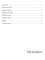
Table des matières
Règles de sécurité............................................................................................................................................................................
Déballage de votre ventilateur .................................................. .....................................................................................................
Installation de votre ventilateur ......................................................................................................................................................
Installation du couvercle décoratif ..................................................................................................................................................
Utilisation de votre émetteur..........................................................................................................................................................
Entretien de votre ventilateur ......................................................................................................................................................
Dépannage.....................................................................................................................................................................................
Caractéristiques techniques .........................................................................................................................................................
1.
2.
3.
9.
10.
12.
13.
14.
La page est en cours de chargement...
La page est en cours de chargement...
La page est en cours de chargement...
La page est en cours de chargement...
La page est en cours de chargement...
La page est en cours de chargement...
La page est en cours de chargement...
La page est en cours de chargement...
La page est en cours de chargement...
La page est en cours de chargement...
La page est en cours de chargement...
La page est en cours de chargement...
La page est en cours de chargement...
La page est en cours de chargement...
La page est en cours de chargement...
La page est en cours de chargement...
La page est en cours de chargement...
La page est en cours de chargement...
La page est en cours de chargement...
La page est en cours de chargement...
La page est en cours de chargement...
La page est en cours de chargement...
La page est en cours de chargement...
La page est en cours de chargement...
La page est en cours de chargement...
La page est en cours de chargement...
La page est en cours de chargement...
La page est en cours de chargement...
La page est en cours de chargement...
La page est en cours de chargement...
La page est en cours de chargement...
-
 1
1
-
 2
2
-
 3
3
-
 4
4
-
 5
5
-
 6
6
-
 7
7
-
 8
8
-
 9
9
-
 10
10
-
 11
11
-
 12
12
-
 13
13
-
 14
14
-
 15
15
-
 16
16
-
 17
17
-
 18
18
-
 19
19
-
 20
20
-
 21
21
-
 22
22
-
 23
23
-
 24
24
-
 25
25
-
 26
26
-
 27
27
-
 28
28
-
 29
29
-
 30
30
-
 31
31
-
 32
32
-
 33
33
-
 34
34
-
 35
35
-
 36
36
-
 37
37
-
 38
38
-
 39
39
-
 40
40
-
 41
41
-
 42
42
-
 43
43
-
 44
44
-
 45
45
-
 46
46
-
 47
47
-
 48
48
-
 49
49
-
 50
50
-
 51
51


Progress Lighting 93138704 C Guide d'installation
- Catégorie
- Ventilateurs ménagers
- Taper
- Guide d'installation
dans d''autres langues
Documents connexes
-
Progress Lighting 93114646 B Guide d'installation
-
Progress Lighting P250000-081 Guide d'installation
-
-
-
-
-
-
-
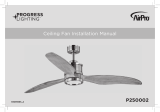 PROGRESS LIGHTNING P250002-143-30 Mode d'emploi
-