Toyota A25 Mode d'emploi

Taper
Mode d'emploi
2001 AVALON (EWD431U) 299
K
2345678121 12 1234 12 12
12 12 12
34 1920
1 234 6 7891011
25242322211715141312 18
5
16
21 3456789101112
13
14 15 16171819 2021222324 25
12 12
12 12 12 1234
123456
7 8 9 101112
AB
242523 26222021 2827
123 456
7 8 9 1011121314151617
1819
AB
123456
7 8 9 101112
AB 12
34 11
2221
109
2019
87
1817
65
1615
43
1413
12
12
9
18
8
1716
76
1514
54
1312
32
11
1
10
12
345678 123456 12 478
910
1112131415 16 17
56
3
12 12
(Manual A/C) BLACK YELLOW YELLOW BLACK
GRAY BLACK
BLACK BLACK BLACK BLACK YELLOW
A25 A26 A27 A28 A29 A30
B1 B2 B3 B4
B5 B6 B7 B8 B9
C1 C2 C3 C4 C5
YELLOW YELLOW
BLACK
C6 C7 C8 C9
C10 C11 C12 C13
2001 AVALON (EWD431U)
54
G ELECTRICAL WIRING ROUTING
: Location of Connector Joining Wire Harness and Wire Harness
: Location of Ground Points
: Location of Splice Points
W-R
7. 5A
GAUGE
1
2
3
4
487
2111
13
4
1
2
3
4
1
2
B18
BL
FROM POWER SOURCE SYSTEM (SEE PAGE 66)
R-L
R-L
G
W-B
W-B
W-B
W-B
W-B
W-B
Y-G
R
L 4
H17
R 6
DELAY
CIRCUIT
S 6
B18
3
4
R 7
BV1
1
G-W
G-R
G-R
G-R
G-R
G-W
G-W
(W/G)
(S/D)(S/D)
C 7
(SHIELDED)
BV1
1
I 5
LL
STOP LIGHT
15
7
TO ABS ECU
BO
50
15A
STOP
IB
IB
REAR LIGHTS
WARNING LIGHT
[COMB. METER]
3C
3C
IE114
STOP LIGHT SW
STOP LIGHT RH
[REAR COMB. LIGHT RH]
STOP LIGHT RH
[REAR COMB. LIGHT LH]
HIGH MOUNTED
STOP LIGHT
[A]
[B]
[I]
[D]
[F]
[H]
[E]
[J]
[M]
[N]
[K]
[L]
[G]
[C]
LIGHT FAILURE SENSOR
2001 AVALON (EWD431U)
4
B HOW TO USE THIS MANUAL
The system shown here is an EXAMPLE ONLY. It is different to the actual
circuit shown in the SYSTEM CIRCUITS SECTION.
2001 AVALON (EWD431U)
M OVERALL ELECTRICAL WIRING DIAGRAM
25 26 27 28
8 AVALON (Cont’ d) (Cont. next page)
A
B
C
D
J
K
I
L
M
N
14 B
IF
9IK2 20IK2
21 A 7 A
1C3
C
B
A
D
+BE
HORNSTOPILLPRGRDAGND1
R- B
R- B
L-O
W- L
W- BW- B
W- B
W- B
R- W
W- B
W- B
W- B
R-B
R-B
L- O
W- L
RDA PRG
15
23
W- B
P- L
G- R
G- R
L- W
W- B
L- W
G- R
W- B
D 8
DOOR CONTROL
RECEIVER
B 4 B 5, AB
Multiplex Communication System * 3 : Taiwan
G-R
14F 4E1
D 7
DIODE(Luggage
Compartment
Light)
4D1
G- R
4E10
L 8
LUGGAGE
COMPARTMENT
LIGHT
G- R
4D10
4E1
W- B
I14
IGNITION KEY
CYLINDER LIGHT
4C1
W- B
4C10
W- B
2
1
W- B
1
2
2
1
A
2
A
IG15
W- B
A
2
DOOR
OFF
ON
A
ON
OFF
DOOR
3
11
2
1
2
BL Roof left
IG1
11
IG1
17
P 9
PERSONAL LIGHT
IA1
4
P-L
P- L
BK Rear quarter inner LH
7ID1
P- L
W- B
V10
VANITY LIGHT LH
I17
INTERIOR LIGHT
W- B
W- B
W- B
P- L
W- B
(*4)
W- B
P- L
W- B
P- L
V11
VANITY LIGHT RH
L
P-L
P- L
L
W- B
2
P- L
P- L
P- LP- LP-L
P- LP-L
GSW
P-L
P-L
A
P-L
19
P- L
G-R
1
R- W
W- B
W- B
J11
JUNCTION
CONNECTOR
R11
REAR INTERIOR
LIGHT LH
R12
REAR INTERIOR
LIGHT RH
E
F
G
H
W- G
W- G
R-B
P- L
E
F
G
H
I
J
511 10
W- G
W- G
R- B
P-L
W- B
W- B
3
1D
BODY ECU
See Stop Light System
<6-3>
1
1J See Horn System
<9-3>
N 3
NOISE FILTER
(Luggage Compartment
Light)
11
22
Left kick panel
8IG1
G- R
P-L
G-R
From Center Airbag
Sensor Assembly
<15-2>
2001 AVALON (EWD431U)
30
F RELAY LOCATIONS
: Engine Room J/B Engine Compartment Left (See Page 20)
2001 AVALON (EWD431U)
80
CHARGING
10A
AM2 5A
ALT- S
D1B1
A1
2C72B11
IF14
76AM2
AM1
ACC
IG1
IG2
ST2
1C7
1A13
5A
ECU- IG
NO. 1
FROM POWER SOURCE SYSTEM (SEE PAGE 72)
1D5
3A2
3A11
II116
IJ16
I 8
2G2
FUSIBLE LINK
BLOCK
BF 6 , F 7A
W-R
W-R
B- O
R- L
BB-L
BW-RW-R
Y
B- L
Y
B- OR- L
Y
BODY
ECU
B 5
IGNITION SW
I15
A3A2GENERATOR BG 1 , G 2A
BATTERY
FL MAIN
3. 0W
120A ALT
D, F 9
R- L
(*1)
6
IG L S B
IC REGULATOR
A1B1
* 1 : W/ DAYTIME RUNNING LIGHT
B- L
R- L
12
11
CHARGE WARNING LIGHT
[MULTI DISPLAY]
M 7
ALTL
2001 AVALON (EWD431U)
112
MULTIPLEX COMMUNICATION SYSTEM
B8B207B
LG
Y- B
L
431
CLTS CLTE CLTB
AUTOMATIC LIGHT
CONTROL SENSOR
A28
LG
4IK1
CLTB A25
1
B3
4F17
4E17
1
B16
4F5
4F14
1
4E5
1
2IA1
LL
O
R- W
R- W
R- W R-W
O
TR+ PCTY RCTY
L 7
LUGGAGE COMPARTMENT
DOOR UNLOCK MOTOR
DOOR COURTESY SW
FRONT RH
D12
DOOR COURTESY SW
REAR LH
D13
DOOR COURTESY SW
REAR RH
D14
CLTECLTS
Y- B
A18
LG- R LG- R
3A43G44H6
3A13 4A6
II222
114
LG- R
D 1
DATA LINK
CONNECTOR 1
D 2
DATA LINK
CONNECTOR 2
LG- R
TC
LG- R
TCTC
L
A5
3D17
3E17
1
R- LR- L
DCTY
D11
DOOR COURTESY SW
FRONT LH
P
L- O
P- B
L
LG
P
W- B
LG
L
P- B
, BB 5
BODY ECU
B 4 A
L- O
W- B
JUNCTION
CONNECTOR
J 9
TKU
B18
1
2
1
IJ
A
4H7
4B7
W-BW-B L- BL
2
A20 BZ
W- B BUZZER P- L
A
LUGGAGE COMPARTMENT
DOOR OPENER SW
L 2 LUGGAGE COMPARTMENT
DOOR OPENER MAIN SW
L 1
W 6
WIRELESS DOOR LOCK BUZZER
W- GW- G
1
2
M
I 9
I14
BUZZER
T 1
THEFT DETERRENT BUZZER
1
2
P- L
P- LW- B
W- B P- L
2001 AVALON (EWD431U)
178
WIRELESS DOOR LOCK CONTROL
10A
ECU- IG
NO. 2
FROM POWER SOURCE SYSTEM (SEE PAGE 72)
25A
DOOR
NO. 1 7. 5A
DOME
B5A21 A7A24
A5B3A17 A11 B18 A20 B14 B15 B13 B2B1
3D17 4F17 4A11
3E17 4E17 4B2
1
1
2
IG
3D9
3D22
B
B1
2
1
IJ
A
4H7
4B7
IF
I 5
IK29IK220
4E
1
4D
1
II
4F8
4E8
4F
21
P- L
21
LSR RDA PRG
DCTY PCTY KSW GND2 TKU BZ GND1 ACT- GND2
B
L-O
L-W
G- R
W- G
G- R
L- W P- L
W- B
51
23
DOOR CONTROL
RECEIVER
D 8
RDA PRG
E+B
BODY ECU BB 4 , B 5A
L- O
W-G
L-W
L-R
L
W-B
W-B
R- L
O
R- Y
W-B
W-B
W-B
L- R
L-W
R- L
O
R-Y
W-B
W-B
W-B
W-B
W- B
W- B
W- B
W-B
DOOR COURTESY SW FRONT LH
D11
DOOR COURTESY SW FRONT RH
D12
UNLOCK WARNING SW
U 1
JUNCTION CONNECTOR
J 4
LUGGAGE COMPARTMENT
DOOR OPENER SW
L 2 LUGGAGE COMPARTMENT
DOOR OPENER MAIN SW
L 1
ACT+ ACTD
A
B
JUNCTION
CONNECTOR
J 9
BUZZER
L
W- BW- BW- B
JUNCTION
CONNECTOR
J 6
L-BL
(TAIWAN)
2
P- L
W-B
15A
DOOR
NO. 2
7
2C12
1J5
L-R
25 A
TR+
LL
LUGGAGE COMPARTMENT
DOOR UNLOCK MOTOR
L 7
IK14
BB
B
1
WIRELESS DOOR LOCK BUZZER
BDR2 SIG BDR1
1
2
1
W 6
M
1D7
G-B
MPX4
B21
G-B
2001 AVALON (EWD431U)
246
REMOTE CONTROL MIRROR (w/o DRIVING POSITION MEMORY)
5A
ECU- ACC
FROM POWER SOURCE SYSTEM (SEE PAGE 72)
1D8
MM MM
IB24IB22IB25IN13IN112 IN12
4F20
4F7
IF
BR- W
LG
BR- Y
LG- B
Y- G
W- B
BR- W
BR- Y
Y- G
LG
LG- B
Y- G
W-B
LG
LG- B
Y- G
910 3 2 7 8
4
GR
MH MV
HR VRHL VL M+ E
B
SELECT SW OPERATION SW
REMOTE CONTROL MIRROR SW
R 5
MH MV M+ MH MV M+
BR- Y
LEFT
RIGHT
UP
DOWN
LEFT/
UP
RIGHT/
DOWN
3C15
3D15
4D2
4F11
GRGR
4H9
4G9
4H
22
Y- G
C1 B1 C3 B4 C2 (*2 *4)
B2 (*2 *3)
C1 B1 C3 B4 C2 (*2 *4)
B2 (*2 *3)
R13 ,
REMOTE CONTROL
MIRROR LH
AB R14,
REMOTE CONTROL
MIRROR RH
AB
Y- G
* 2 : EXCEPT TAIWAN
* 1 : TAIWAN
* 3 : W/ MIRROR HEATER
* 4 : W/O MIRROR HEATER
A7 (*1)A7 (*1)
A6A3A3A6
, C , C
2001 AVALON (EWD431U) 247
R5 REMOTE CONTROL MIRROR SW
7-8 : Continuity with the operation SW at UP or LEFT position
4-7 : Continuity with the operation SW at DOWN or RIGHT position
4-GROUND : Approx. 12 volts with the ignition SW at ACC or ON position
: PARTS LOCATION
Code See Page Code See Page Code See Page
R5
47 (Column Shift)
R13
B51
R14
B51
R5 49 (Floor Shift) R13 C51 R14 C51
R13 A 51 R14 A 51
: JUNCTION BLOCK AND WIRE HARNESS CONNECTOR
Code See Page Junction Block and Wire Harness (Connector Location)
1D 27 Cowl Wire and Driver Side J/B (Lower Finish Panel)
3C
34
Cowl Wire and J/B No 3 (Left Kick Panel)
3D 34 Cowl Wire and J/B No.3 (Left Kick Panel)
4D 38 Cowl Wire and J/B No.4 (Right Kick Panel)
4F
4G 39 Instrument Panel Wire and J/B No.4 (Right Kick Panel)
4H
(g )
: CONNECTOR JOINING WIRE HARNESS AND WIRE HARNESS
Code See Page Joining Wire Harness and Wire Harness (Connector Location)
IB2
56 (Column Shift)
Front Door LH Wire and Instrument Panel Wire (Left Kick Panel)
IB2 60 (Floor Shift) Front Door LH Wire and Instrument Panel Wire (Left Kick Panel)
IN1
58 (Column Shift)
Front Door RH Wire and Instrument Panel Wire (Right Kick Panel)
IN1 62 (Floor Shift) Front Door RH Wire and Instrument Panel Wire (Right Kick Panel)
: GROUND POINTS
Code See Page Ground Points Location
IF
56 (Column Shift)
Left Kick Panel
IF 60 (Floor Shift) Left Kick Panel
SERVICE HINTS
2001 AVALON (EWD431U)
260
COMBINATION METER
O/D OFF
FUEL
FUEL GAUGE
TEMP. GAUGE
TACHOMETER
SPEEDOMETER
B2B3B4B5B6B8B9A7
A14 A15B12B11
W
BR
G
L
Y
R
W
R
Y
L
G
BR
BR- W
14 B
BR- W I10I10
B13 B10
L
Y- R
L
P- B
L- R
P- L
L-Y
W-G
P- B
L- R
P- L
L- Y
(*3)
G- O
FROM POWER SOURCE SYSTEM (SEE PAGE 72)
1B13
3C23F11
3F2
7. 5A
ECU- B
FROM POWER SOURCE SYSTEM (SEE PAGE 72)
1B9
3C
5
3F
14
Y- R
Y- R
W- G
COMBINATION METER
B
C 9 , C10
A
Y- R
G G
A20
IH
BRBR
10A
ECU- IG
NO. 2
TO ENGINE CONTROL MODULE
2001 AVALON (EWD431U)
266
RADIATOR FAN AND CONDENSER FAN
5A
ECU- IG
NO. 1
FROM POWER SOURCE SYSTEM (SEE PAGE 72)
1D5
3A2
3H11 3H2
IF34IF315
3
23
15
3
33
II29
1
2
1
1H1
1I2
30A
RDI
2E6
30A
CDS
2E5
2
1
52
31
33
33
2F72D32D2
2D12F12 2F6
EC12
ED
2F4
2D5
EC11
1
2
1
2
2
3
2D7
24
13
5
33 3
33
6
11
22
Y
B
L- B
Y
Y
Y
Y- GLG- BLG- R
Y- G Y- G Y- G
L
G
GW-B
ENGINE
CONTROL
MODULE
E 7
A/C CONDENSER
FAN MOTOR
A 2
Y
B
W- R
Y
G
L
W-R
B- R
WATER TEMP. SW
NO. 2
W 5
ACMG
W-B GW- B
W-B
RADIATOR FAN
MOTOR
R 1
WATER TEMP. SW
NO. 1
W 4
FAN
NO. 3
RELAY
FAN
NO. 1
RELAY
FAN
NO. 2
RELAY
L- B
Y
W- R
2F5
IF36
GG
26
CF
GDIODE (A/C)
D 4
G
2D6
W-B L
A 4
A/C SINGLE
PRESSURE SW
IF110
82D
W-B
W- B
M
M
2001 AVALON (EWD431U) 267
The radiator fan motor and A/C condenser fan motor operates according to the water temp. SW NO.1, water temp. SW
NO.2, A/C single pressure SW, and the A/C system condition. The FAN NO.1 relay, FAN NO.2 relay, FAN NO.3 relay are
turned on/off, to operate the fan motors at low speed (In series), or high speed (In parallel).
1. LOW SPEED OPERATION
Either when the A/C system is operating, or when the water temp. SW NO.2 is on, the radiator fan motor and A/C condenser
fan motor operates at low speed.
2. HIGH SPEED OPERATION
Either when the A/C system is operating, or when the water temp. SW NO.2 is on, if the water temp. SW NO.1 or A/C single
pressure SW is on, the radiator fan motor and A/C condenser fan motor operates at high speed.
A3 A/C SINGLE PRESSURE SW
3-2 : Open above approx. 15.5 kgf/cm2 (224 psi, 1520 kpa)
Close below approx. 12.5 kgf/cm2 (181 psi, 1225 kpa)
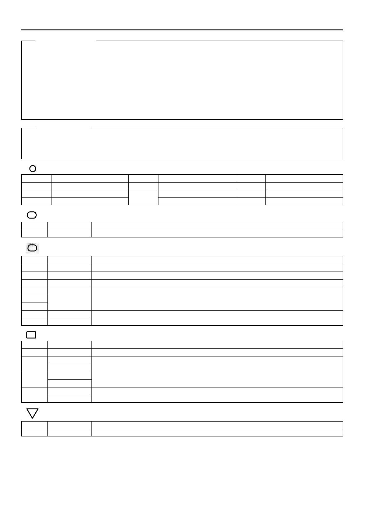
: PARTS LOCATION
Code See Page Code See Page Code See Page
A2 44 D4 48 (Floor Shift) R1 45
A4 44
E7
46 (Column Shift) W4 45
D4 46 (Column Shift) E7 48 (Floor Shift) W5 45
: RELAY BLOCKS
Code See Page Relay Blocks (Relay Block Location)
324 Engine Room R/B No.3 (Near the Radiator Fan)
: JUNCTION BLOCK AND WIRE HARNESS CONNECTOR
Code See Page Junction Block and Wire Harness (Connector Location)
1D 27 Cowl Wire and Driver Side J/B (Lower Finish Panel)
1H 27 Engine Room Main Wire and Driver Side J/B (Lower Finish Panel)
1I 27 Cowl Wire and Driver Side J/B (Lower Finish Panel)
2D
2E 30 Engine Room Main Wire and Engine Room J/B (Engine Compartment Left)
2F
gg(g)
3A 34
Cowl Wire and J/B No 3 (Left Kick Panel)
3H 35 Cowl Wire and J/B No.3 (Left Kick Panel)
: CONNECTOR JOINING WIRE HARNESS AND WIRE HARNESS
Code See Page Joining Wire Harness and Wire Harness (Connector Location)
EC1 54 Engine Room Main Wire and Engine Room No.3 Wire (Near the Radiator Fan)
IF1
56 (Column Shift)
IF1 60 (Floor Shift)
Engine Room Main Wire and Cowl Wire (Left Side of Instrument Panel)
IF3
56 (Column Shift) Engine Room Main Wire and Cowl Wire (Left Side of Instrument Panel)
IF3 60 (Floor Shift)
II2
58 (Column Shift)
Engine Wire and Cowl Wire (Behind the Glove Box)
II2 62 (Floor Shift) Engine Wire and Cowl Wire (Behind the Glove Box)
: GROUND POINTS
Code See Page Ground Points Location
ED 54 Front Side of Left Fender
SYSTEM OUTLINE
SERVICE HINTS
To Ignition SW
IG Terminal
Fuse
VoltmeterSW 1
Relay
SW 2 Solenoid
[A]
[B]
[C]
Ohmmeter
SW
Ohmmeter
Diode
Digital Type Analog Type
2001 AVALON (EWD431U)
12
C TROUBLESHOOTING
VOLTAGE CHECK
(a) Establish conditions in which voltage is present at the check
point.
Example:
[A] - Ignition SW on
[B] - Ignition SW and SW 1 on
[C] - Ignition SW, SW 1 and Relay on (SW 2 off)
(b) Using a voltmeter, connect the negative lead to a good ground
point or negative battery terminal, and the positive lead to the
connector or component terminal.
This check can be done with a test light instead of a voltmeter.
CONTINUITY AND RESISTANCE CHECK
(a) Disconnect the battery terminal or wire so there is no voltage
between the check points.
(b) Contact the two leads of an ohmmeter to each of the check
points.
If the circuit has diodes, reverse the two leads and check
again.
When contacting the negative lead to the diode positive side
and the positive lead to the negative side, there should be
continuity.
When contacting the two leads in reverse, there should be no
continuity.
(c) Use a volt/ohmmeter with high impedance (10 k/V
minimum) for troubleshooting of the electrical circuit.
Retainer at
Full Lock Position
[Male] [Female]
Retainer at
Temporary Lock Position
Locking Lug
Tool
2001 AVALON (EWD431U)
16
C TROUBLESHOOTING
Push the terminal retainer down to the temporary lock position.
(c) Release the locking lug from terminal and pull the terminal out
from rear.
4. INSTALL TERMINAL TO CONNECTOR
(a) Insert the terminal.
HINT:
1. Make sure the terminal is positioned correctly.
2. Insert the terminal until the locking lug locks firmly.
3. Insert the terminal with terminal retainer in the temporary lock
position.
(b) Push the secondary locking device or terminal retainer in to
the full lock position.
5. CONNECT CONNECTOR
  • Page 1 1
  • Page 2 2
  • Page 3 3
  • Page 4 4
  • Page 5 5
  • Page 6 6
  • Page 7 7
  • Page 8 8
  • Page 9 9
  • Page 10 10
  • Page 11 11
  • Page 12 12
  • Page 13 13
  • Page 14 14
  • Page 15 15

Toyota A25 Mode d'emploi

Taper
Mode d'emploi