
ITALIANO
DC6002I – DC6002I/BR
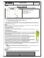
CONTATTO MAGNETICO CON INGRESSI FILARI BIANCO O MARRONE
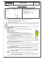
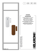
1. Indicatore LED rosso / Pulsante Test
2. Tappi per coprire i fori di montaggio
3. Isolante di batteria
4. Tamper (antimanomissione)
5. Fori di montaggio
LED
In modalità di funzionamento normale, l’indicatore LED è spento, eccetto che nelle seguenti situazioni:
Quando l'interruttore tamper del contatto viene aperto o chiuso
Quando il contatto è allarmato con tamper aperto o con batteria scarica
Quando il contatto entra in modalità Test
Il LED non lampeggia se il tamper e la batteria del contatto funzionano normalmente e il dispositivo non è in modalità Test.
Il LED lampeggia per indicare la trasmissione di un segnale e lampeggia rapidamente 2 volte quando riceve un segnale di
riconoscimento dall’unità di controllo.
Tamper
L’interruttore magnetico interno rileva l’apertura e la chiusura della porta con il magnete associato. Il tamper protegge il contatto
da tentativi di manomissione o rimozione dalla superficie di installazione.
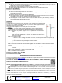
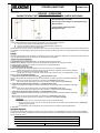
Jumper e morsetti interni
1. e 2. Morsettiere. Per il collegamento si veda la Tabella 1.
La segnalazione di un allarme sull’ingresso della morsettiera 2 sarà dello stesso tipo di quello segnalato
dall’apertura della porta.
3. Jumper Riservato (JP2)
4. Jumper abilitazione allarme porta (JP3)
Questo jumper permette di abilitare/disabilitare l’allarme provocato dall’apertura porta. Se il jumper è su ON (il
jumper è inserito sui due pin), la rilevazione è disabilitata e rimangono abilitati gli allarmi di tipo tapparella e
ingresso NC. Se il jumper è su OFF (il jumper è rimosso o “collocato” su un pin), la rilevazione è abilitata
(impostazione di default).
5. Jumper Impostazione rivelatore apertura tapparelle
-
5 impulsi/disabilitato (JP4)
Questo jumper permette di selezionare quanti impulsi sono necessari per attivare l’allarme di apertura tapparelle.
Con il jumper su ON, l’allarme viene generato quando vengono contati 5 impulsi in 10 secondi. Se il jumper è
su OFF, l’allarme non viene attivato dopo 5 impulsi in 10 secondi (impostazione predefinita).
6. Jumper Impostazione rivelatore apertura tapparelle
-
6 impulsi/disabilitato (JP5)
Questo jumper permette di selezionare quanti impulsi sono necessari per attivare l’allarme di apertura tapparelle.
Con il jumper su ON, l’allarme viene generato quando vengono contati 6 impulsi in 10 secondi. Se il jumper è
su OFF, l’allarme non viene attivato dopo 6 impulsi in 10 secondi (impostazione predefinita).
7. Jumper Impostazione rivelatore apertura tapparelle
-
8 impulsi/disabilitato (JP6)
Questo jumper permette di selezionare quanti impulsi sono necessari per attivare l’allarme di apertura tapparelle. Con il jumper
su ON, l’allarme viene generato quando vengono contati 8 impulsi in 10 secondi. Se il jumper è su OFF, l’allarme non viene
attivato dopo 8 impulsi in 10 secondi (impostazione predefinita).
<
<N
NO
OT
TA
A>
>
I jumper JP4, JP5 e JP6 possono essere impostati su ON solo uno alla volta.
Se più di un jumper JP4, JP5 e JP6 o nessuno di essi è impostato su ON, l’allarme si attiverà dopo 5 impulsi contati in
10 secondi.
Il conteggio degli impulsi sarà azzerato se non saranna contati impulsi entro 10 secondi .
8. Pulsante Test
Morsettiere
Nella tabella sottostante vengono visualizzati i collegamenti disponibili per le morsettiere 1 e 2. Nel caso di collegamento della
morsettiera 2, la segnalazione di un allarme su questo ingresso sarà dello stesso tipo di quello segnalato dall’apertura della porta.
TABELLA 1 – COLLEGAMENTI ALLE MORSETTIERE DEL DC6002I
MORSETTIERA 1 MORSETTIERA 2
Rivelatore apertura tapparelle Rivelatore Rottura Vetri (tipo GD05PL)
Rivelatore inerziale (tipo VSD3 o MMZ01) Dispositivo con contatto NC (Normalmente Chiuso)
GUIDA RAPIDA
DS80MM1G-003A
5
5

Modalità Test
Ogni volta che il pulsante di Test viene premuto, il contatto trasmette un segnale all’unità di controllo per un test della
portata radio e attiva per 3 minuti la modalità di Test.
Durante il Test, il LED si accende ogni qualvolta il contatto venga attivato.
Ad ogni ulteriore pressione del pulsante di Test, la modalità Test viene prolungata di altri 3 minuti.
Procedura di apprendimento
Rimuovere l’isolante dalla batteria.
Attivare la funzione di apprendimento sull’unità di controllo.
Tramite la funzione di apprendimento, abbinare l'interruttore magnetico interno/tamper e gli ingressi filari su un
ingresso dell’unità di controllo.
Premere il pulsante di test per l’apprendimento del dispositivo.
Se il segnale è ricevuto dall’unità di controllo, essa visualizzerà le informazioni corrispondenti. Fare riferimento al
manuale dell’unità di controllo per completare la procedura di apprendimento.
Una volta appreso il contatto, impostare l’unità di controllo in modalità “Walk Test” (Test movimento), mantenere il
contatto nella posizione desiderata e premere il pulsante Test per confermare che la posizione scelta si trovi
all’interno della portata radio dell’unità di controllo.
Una volta accertato che il contatto funzioni nella posizione desiderata, è possibile procedere all'installazione.
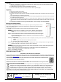
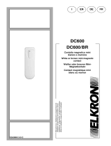
Installazione
Il contatto deve essere posizionato sul telaio della porta, mentre il magnete deve essere posizionato
sulla porta. Se il contatto è posizionato sulla porta e la porta viene aperta troppo velocemente, la
distanza di trasmissione può essere ridotta.
Con la porta chiusa, il magnete non deve essere a più di 15 mm dal contatto.
<
<N
NO
OT
TA
A>
>
Se il contatto non può essere installato sul telaio della porta, è possibile collegare rivelatori di
apertura aggiuntivi sugli ingressi filari (per i dettagli, fare riferimento al manuale completo).
Passo 1: Individuare una posizione adeguata vicino alla porta/finestra dove posizionare il
contatto.
Passo 2: Il contatto presenta 2 tacche su un lato, che indicano la posizione del magnete. Il
contatto può essere installato dritto o capovolto, per garantire che le tacche siano
allineate con il magnete.
Passo 3: Per montare il contatto:
(i) Utilizzando i 2 fori di montaggio del contatto come dima, marcare la posizione dei fori nella posizione più
adeguata.
(ii) Inserire i tasselli se si esegue il fissaggio su intonaco o mattoni.
(iii) Avvitare il contatto ai tasselli.
Passo 4: Posizionare il magnete sulla porta utilizzando il biadesivo o le viti in dotazione. Il magnete deve essere allineato
alle tacche laterali del contatto come illustrato in figura.
<
<N
NO
OT
TA
A>
>
Assicurarsi che la molla del tamper faccia contatto contro la superficie di appoggio passando attraverso l’apertura
del tamper.
Passo 5: Testare il contatto aprendo e chiudendo la porta o la finestra con l’unità di controllo in modalità “Walk test”.
Passo 6: Inserire i tappi bianchi nei due fori di montaggio del contatto.
Passo 7: L’installazione è stata completata.
Frequenza radio di utilizzo: 868,6 - 868,7 MHz
Potenza radio trasmessa: 1,81 dBm
DICHIARAZIONE DI CONFORMITÀ UE SEMPLIFICATA
Il fabbricante, URMET S.p.A., dichiara che il tipo di apparecchiatura radio: CONTATTI MAGNETICI CON INGRESSI FILARI
DC6002I e DC6002I/BR è conforme alla direttiva 2014/53/UE. Il testo completo della dichiarazione di conformità UE è disponibile
al seguente indirizzo Internet: www.elkron.com.
CLICCARE SUL SEGUENTE LINK DEL SITO ELKRON PER ACCEDERE ALLA SCHEDA TECNICA DEL
PRODOTTO E SCARICARE IL MANUALE COMPLETO:
DIRETTIVA 2012/19/UE DEL PARLAMENTO EUROPEO E DEL CONSIGLIO del 4 luglio 2012 sui rifiuti di apparecchiature elettriche ed
elettroniche (RAEE). Il simbolo del cassonetto barrato riportato sull’apparecchiatura o sulla sua confezione indica che il prodotto alla
fine della propria vita utile deve essere raccolto separatamente dagli altri rifiuti. L’utente dovrà, pertanto, conferire l’apparecchiatura
giunta a fine vita agli idonei centri comunali di raccolta differenziata dei rifiuti elettrotecnici ed elettronici. In alternativa alla gestione
autonoma è possibile consegnare l’apparecchiatura che si desidera smaltire al rivenditore, al momento dell’acquisto di una nuova
apparecchiatura di tipo equivalente. Presso i rivenditori di prodotti elettronici con superficie di vendita di almeno 400 m2 è inoltre
possibile consegnare gratuitamente, senza obbligo di acquisto, i prodotti elettronici da smaltire con dimensione massima inferiore a 25 cm.
L’adeguata raccolta differenziata per l’avvio successivo dell’apparecchiatura dismessa al riciclaggio, al trattamento e allo smaltimento
ambientalmente compatibile contribuisce ad evitare possibili effetti negativi sull’ambiente e sulla salute e favorisce il reimpiego e/o riciclo dei
materiali di cui è composta l’apparecchiatura.
ELKRON
Tel. +39 011.3986711 - Fax +39 011.3986703
www.elkron.com – mail to: info@elkron.it
ELKRON è un marchio commerciale di URMET S.p.A.
Via Bologna 188/C – 10154 Torino (TO) Italia
HUwww.urmet.comUH MADE IN TIWAN
Tacche

ENGLISH
DC6002I – DC6002I/BR
WHITE/BROWN MAGNETIC CONTACTS WITH WIRED INPUTS
1. Red LED indicator / Test button
2. Plugs for covering mounting holes
3. Battery insulation
4. Tamper switch
5. Mounting holes
LED
In normal operating mode, the LED indicator is off, except for the following situations:
When the tamper switch of the contact is opened or closed
When the contact is in alarm with the tamper switch open or the battery flat
When the contact is in Test mode
The LED does not blink if the tamper switch and the battery contact are working normally and the device is not in Test mode.
The LED blinks to indicate that a signal is being transmitted and blinks rapidly twice when it receives a recognition signal from the
control unit.
Tamper
The internal magnetic switch detects the opening and closing of the door with the associated magnet.The tamper switch protects
the contact from tampering attempts or attempts remove it from the installation surface.
Jumper and internal terminals
1. and 2. Terminal blocks. For connection, see Table 1 in the Contact operation section
Terminals 2: the signalling of an alarm on this input will be of the same type as that indicated by the
opening of the door.
3. Reserved jumper (JP2)
4. Door alarm enabled jumper (JP3)
This jumper can be used to enable/disable the alarm caused by opening the door.
If the jumper is ON (the jumper is inserted on the two pins), detection is deactivated and the roller and
NC input alarms remain enabled.
If the jumper is OFF (jumper removed or "arranged" on a pin), detection is enabled (default setting).
5. Roller open detector setting jumper
-
5 pulses/off (JP4)
This jumper can be used to select how many pulses are needed to activate the roller opening alarm.
With the jumper set to ON, the alarm is generated when 5 pulses are counted in 10 seconds.
If the jumper is set to OFF, the alarm is not activated after 5 pulses in 10 seconds (default setting).
6. Roller open detector setting jumper
-
6 pulses/off (JP5)
This jumper can be used to select how many pulses are needed to activate the roller opening alarm.
With the jumper set to ON, the alarm is generated when 6 pulses are counted in 10 seconds.
If the jumper is set to OFF, the alarm is not activated after 6 pulses in 10 seconds (default setting).
7. Roller open detector setting jumper
-
8 pulses/off (JP6)
This jumper can be used to select how many pulses are needed to activate the roller opening alarm.
With the jumper set to ON, the alarm is generated when 8 pulses are counted in 10 seconds.
If the jumper is set to OFF, the alarm is not activated after 8 pulses in 10 seconds (default setting).
<
<N
NO
OT
TE
ES
S>
>
The jumpers JP4, JP5 and JP6 may be set to ON only once.
If more than one jumper JP4, JP5 and JP6 or none are set to ON, the alarm will be activated after 5
pulses counted in 10 seconds.
The pulse count will be reset if no pulses are counted within 10 seconds.
8. Test button
Wired terminals
The table below shows the connections available for terminal blocks 1 and 2. In case of connection of the terminal block 2,
the signalling of an alarm on this input will be of the same type as that indicated by the opening of the door.
TABLE 1
–
CONNECTIONS TO THE TERMINALS OF DC6002I
TERMINAL BLOCK 1
TERMINAL BLOCK 2
Roller opening detector
Glass Break Detector (e.g. GD05PL)
Inertial detector (e.g. VSD3 or MMZ01)
Device with NC contact (Normally Closed)
QUICK GUIDE
DS80MM1G-003A
5
5

Test mode
Whenever the Test button is pressed, the contact transmits a signal to the control unit to test the radio range and
activates Test mode for three minutes.
The LED lights up whenever the contact is activated during the Test.
Test mode is extended by three more minutes if the Test button is pressed again.
Preparation
Remove the insulation of the battery.
Activate the learn function on the control unit.
By means of the learn function, pair the internal/tamper magnetic switch and the wired inputs to an input of the control
unit.
Press the test button for the learning of the device.
If the signal is received from the control unit it will show the corresponding information. Refer to the control unit manual
to complete the learning procedure.
Once the contact learning procedure has been run, set the control unit to “Walk Test” mode, holding the contact in the
required position and press the Test button to confirm that the chosen position is within the radio range of the control
unit.
Proceed with the installation after having ascertained that the contact is working in the desired position.
Mounting and installation methods
The contact must be positioned on the door frame while the magnet must be positioned on the
door. If the contact is positioned on the door and the door is opening too fast, the transmission
distance may be reduced.
The magnet must not be more than 15 mm from the contact when the door is closed.
<
<N
NO
OT
TE
E>
>
If the contact cannot be installed on the door frame, additional opening detectors
can be used on the wired inputs (see the “How to use the terminals” section for
details).
Step 1: Identify an appropriate position near the door/window where the contact is positioned.
Step 2: The contact has two rib-marks on one side which indicate the position of the magnet.
The contact may be installed straight or upside down to ensure that the rib-marks are
aligned with the magnet.
Step 3: To fit the contact:
(i) Using the two mounting holes of the contact as a template, mark the position of the holes in the more suitable
position.
(ii) Insert the anchor bolts if the device is fixed to plaster or bricks.
(iii) Screw the contact onto the anchor bolts.
Step 4: Position the magnet on the door using the two-sided adhesive or the screws provided. The magnet must be
aligned with the side rib-marks of the contact as shown in the figure.
<
<N
NO
OT
TE
E>
>
Make sure that the spring of the tamper switch makes contact against the resting surface passing through the
opening of the tamper switch.
Step 5: Test the contact by opening and closing door or window with the control unit in “Walk test” mode.
Step 6: Insert the white plugs in the two mounting holes of the contact.
Step 7: The installation is complete.
Radio frequency of use: 868,6 - 868,7 MHz
Radio power transmitted: 1,81 dBm
SIMPLIFIED EU DECLARATION OF CONFORMITY
Hereby, URMET S.p.A. declares that the radio equipment type: WHITE/BROWN MAGNETIC CONTACTS WITH WIRED INPUTS
DC6002I is in compliance with Directive 2014/53/EU. The full text of the EU declaration of conformity is available at the following
internet address: www.elkron.com.
CLICK ON THE FOLLOWING LINK OF THE ELKRON SITE TO ACCESS THE PRODUCT TECHNICAL SHEET
AND DOWNLOAD THE COMPLETE MANUAL:
DIRECTIVE 2012/19/EU OF THE EUROPEAN PARLIAMENT AND OF THE COUNCIL of 4 July 2012 on waste
electrical and electronic equipment (WEEE).
The symbol of the crossed-out wheeled bin on the product or on its packaging indicates that this product must not be
disposed of with your other household waste. Instead, it is your responsibility to dispose of your waste equipment by
handing it over to a designated collection point for the recycling of waste electrical and electronic equipment. The
separate collection and recycling of your waste equipment at the time of disposal will help to conserve natural
resources and ensure that it is recycled in a manner that protects human health and the environment. For more information
about where you can drop off your waste equipment for recycling, please contact your local city office, your household waste
disposal service or the shop where you purchased the product.
ELKRON
Tel. +39 011.3986711 - Fax +39 011.3986703
www.elkron.com – mail to: info@elkron.it
ELKRON is a trademark of URMET S.p.A.
Via Bologna 188/C – 10154 Turin (TO) Italy
www.urmet.com
MADE IN TAIWAN

FRANÇAIS
DC6002I – DC6002I/BR
CONTACT MAGNÉTIQUE AVEC ENTRÉES FILAIRES BLANC/ MARRON
1. Indicateur LED rouge / Touche Test
2. Bouchons pour couvrir les trous de montage
3. Isolateur de batterie
4. Interrupteur tamper (anti-sabotage)
5. Trous de montage
LED
En mode de fonctionnement normal, l’indicateur LED est éteint, sauf dans les conditions suivantes :
Quand l’interrupteur tamper du contact est ouvert ou fermé
Quand le contact est activé avec tamper ouvert ou batterie épuisée
Quand le contact entre en mode Test
La LED ne clignote pas si le tamper et la batterie du contact fonctionnent normalement et le dispositif n’est pas en mode Test.
La LED clignote pour montrer la transmission d’un signal et clignote vite 2 fois quand elle reçoit un signal d’identification de l’unité
de contrôle.
Tamper
L’aimant permet à l’interrupteur magnétique de détecter l’ouverture et la fermeture de la porte. Le tamper protège le contact
contre les tentatives de sabotage ou d’arrachement de la surface d’installation.
Cavaliers et bornes internes
1. et 2. Bornes. Pour la connexion, voir le tableau 1 dans la section relative au fonctionnement
du contact.
Bornes 2 : La signalisation d’une alarme sur cette entrée sera du même type que celle
signalée par l’ouverture de la porte.
3. Cavalier réservé (JP2)
4. Cavalier activation alarme porte (JP3)
Ce cavalier permet d’activer/exclure l’alarme déclenchée par l’ouverture de la porte.
Si le cavalier est configuré sur ON (le cavalier est inséré entre les deux bornes), la
détection est exclue, tandis que les alarmes volet roulant et entrée NF demeurent activées.
Si le cavalier est configuré sur OFF (le cavalier est enlevé ou placé sur une borne), la
détection est activée (configuration par défaut).
5. Cavalier Configuration détecteur ouverture volets roulants – 5 impulsions / exclu
(JP4)
Ce cavalier permet de sélectionner le nombre d’impulsions nécessaires pour activer l’alarme
d’ouverture des volets roulants.
Si le cavalier est configuré sur ON, l’alarme est déclenchée après 5 impulsions pendant
10 secondes.
Si le cavalier est configuré sur OFF, l’alarme n’est pas déclenchée après 5 impulsions
pendant 10 secondes (configuration par défaut).
6. Cavalier Configuration détecteur ouverture volets roulants – 6 impulsions / exclu
(JP5)
Ce cavalier permet de sélectionner le nombre d’impulsions nécessaires pour activer l’alarme d’ouverture des volets
roulants.
Si le cavalier est configuré sur ON, l’alarme est déclenchée après 6 impulsions pendant 10 secondes.
Si le cavalier est configuré sur OFF, l’alarme n’est pas déclenchée après 6 impulsions pendant 10
secondes (configuration par défaut).
7. Cavalier Configuration détecteur ouverture volets roulants – 8 impulsions / exclu (JP6)
Ce cavalier permet de sélectionner le nombre d’impulsions nécessaires pour activer l’alarme d’ouverture des volets
roulants.
Si le cavalier est configuré sur ON, l’alarme est déclenchée après 8 impulsions pendant 10 secondes.
Si le cavalier est configuré sur OFF, l’alarme n’est pas déclenchée après 8 impulsions pendant 10
secondes (configuration par défaut).
<
<N
NO
OT
TE
E>
>
Les cavaliers JP4, JP5 et JP6 peuvent être configurés sur ON seulement un à la fois.
Si plus d’un cavalier JP4, JP5 et JP6 ou aucun d’eux n’est configuré sur ON, l’alarme sera activée après 5
impulsions comptées pendant 10 secondes.
Le comptage des impulsions sera mis à zéro si aucune impulsion ne sera comptée dans 10 secondes.
8. Touche Test
GUIDE RAPIDE
DS80MM1G-003A
5
5

Bornes filaires
Le tableau ci-dessous indique les connexions disponibles pour les borniers 1 et 2. En cas de connexion du bornier 2, la
signalisation d’une alarme sur cette entrée sera du même type que celle signalée à l’ouverture de la porte.
TABLEAU 1
-
CONNEXION DES BORNES DU DC6002I
BORNES 1
BORNES 2
Détecteur d’ouverture des volets roulants
Détecteur de bris de verre (tipo GD05PL)
Détecteur inertiel (tipo VSD3 o MMZ01)
Appareil avec contact NC (normalement fermé)
Mode Test
1. À chaque pression de la touche de Test le contact transmet un signal à l’unité de contrôle pour tester la portée radio et active
le mode Test pendant 3 minutes.
2. Pendant le Test, la LED s’allume chaque fois que le contact est activé.
3. À chaque nouvelle pression de la touche de Test, le mode Test est prolongé de 3 minutes.
Procédure d’apprentissage
1. Enlever l’isolateur de la batterie.
2. Activer la fonction d’apprentissage sur l’unité de contrôle.
3. Avec la fonction d’apprentissage, associer l’interrupteur magnétique interne/tamper et les entrées filaires sur une entrée de
l’unité de contrôle.
4. Appuyer sur la touche de test pour l’apprentissage du dispositif.
5. Si le signal est reçu par l’unité de contrôle, celle-ci affichera les informations relatives. Consulter le manuel de l’unité de
contrôle pour compléter la procédure d’apprentissage.
6. Après que le contact a été acquis, configurer l’unité de contrôle en mode “Walk Test” (Test mouvement), maintenir le contact
dans la position désirée et appuyer sur la touche Test pour confirmer que la position choisie est comprise dans la portée
radio de l’unité de contrôle.
7. Après avoir vérifié que le contact fonctionne dans la position désirée il est possible de procéder avec l’installation.
Modalité de montage et d’installation
Le contact doit être placé sur le châssis de la porte, tandis que l’aimant doit être fixé à la porte.
Si le contact est placé sur la porte et celle-ci est ouverte trop vite, la distance de transmission
peut être réduite.
Avec la porte fermée, l’aimant ne doit pas se trouver à plus de 15 mm du contact.
<
<N
NO
OT
TE
E>
>
Si le contact ne peut pas être installé sur le châssis de la porte, des détecteurs d’ouverture
supplémentaires peuvent être raccordés sur les entrées filaires (pour les détails, consulter
la section « Utilisation des bornes »).
Ier étape : Trouver une position appropriée près de la porte/fenêtre où placer le contact.
IIème étape : Sur un côté du contact il y 2 crans qui indiquent la position de l’aimant. Le contact peut
être installé droit ou renversé ; les crans doivent être alignés avec l’aimant.
IIIème étape : Pour monter le contact :
Utiliser les 2 trous de montage du contact comme gabarit pour marquer la position des
trous dans la position la plus appropriée.
Insérer les chevilles si le contact est fixé sur du plâtre ou des briques.
Visser le contact dans les chevilles.
IVème étape : Fixer l’aimant à la porte avec le ruban biadhésif ou les vis fournies. L’aimant doit être aligné aux crans
latéraux du contact, comme montré dans la figure.
<
<N
NO
OT
TE
E>
>
Vérifier que le ressort de l’interrupteur tamper soit en contact avec la surface d’appui et qu’il passe à travers
l’ouverture de l’interrupteur tamper.
Vème étape : Avec l’unité de contrôle en mode “Walk test”, ouvrir et fermer la porte ou la fenêtre pour tester le contact.
VIème étape : Insérer les bouchons blancs dans les deux trous de montage du contact.
VIIème étape : L’installation est complète.
Fréquence radio d'utilisation : 868,6 - 868,7 MHz
Puissance radio transmise : 1,81 dBm
DECLARATION UE DE CONFORMITÉ SIMPLIFIÉE
Le fabricant, URMET S.p.A., déclare que l’équipement radio : CONTACT MAGNÉTIQUE AVEC ENTRÉES FILAIRES BLANC/
MARRON DC6002Iest conforme à la directive 2014/53/UE. Le texte complet de la déclaration UE de conformité est disponible à
l’adresse internet suivant : www.elkron.com.
CLIQUEZ SUR LE LIEN SUIVANT DU SITE ELKRON POUR ACCÉDER À LA FICHE TECHNIQUE DU PRODUIT
ET TÉLÉCHARGER LE MANUEL COMPLET
LES BONS GESTES DE MISE AU REBUT DE CE PRODUIT (Déchets d’équipements électriques et
électroniques)
Ce symbole apposé sur le produit, ses accessoires ou sa documentation indique que ni le produit, ni ses accessoires
électroniques usagés (chargeur, casque audio, câble USB, etc.), ne peuvent être jetés avec les autres déchets
ménagers. La mise au rebut incontrôlée des déchets présentant des risques environnementaux et de santé publique,
veuillez séparer vos produits et accessoires usagés des autres déchets. Vous favoriserez ainsi le recyclage de la matière
qui les compose dans le cadre d’un développement durable.
ELKRON
Tel. +39 011.3986711 - Fax +39 011.3986703
www.elkron.com – mail to: info@elkron.it
ELKRON est une marque commerciale de URMET S.p.A.
Via Bologna 188/C – 10154 Turin (TO) Italie
www.urmet.com
MADE IN TAIWAN
Crans

DEUTSCH
DC6002I – DC6002I/BR
MAGNETKONTAKT MIT VERKABELTEN EINGÄNGEN IN WEIß UND BRAUN
1. Rote LED-Anzeige / Test-Taste
2. Abdeckungen zum Verbergen der Montageöffnungen
3. Batterie-Isolator
4. Tamper-Schalter (Sabotageschutz)
5. Montagebohrungen
LED
In der normalen Betriebsart ist die LED-Anzeige ausgeschaltet, außer in den folgenden Situationen:
Wenn der Tamper-Schalter des Kontakts geöffnet oder geschlossen wird
Wenn der Kontakt bei geöffnetem Tamper oder entladener Batterie ausgelöst wird
Wenn der Kontakt sich in den Test-Modus begibt
Die LED blinkt nicht, wenn der Tamper und die Batterie des Kontakts normal funktionieren und die Vorrichtung sich nicht im Test-Modus befindet.
Die LED blinkt, um die Übertragung eines Signals anzuzeigen und blinkt zwei Mal schnell, wenn sie ein Signal des Erkennens vom Steuergerät
empfängt.
Tamper
Der innere Magnetschalter erfasst das Öffnen und Schließen der Tür mit dem zugeordneten Magneten. Der Tamper schützt den Kontakt vor
Versuchen der Beschädigung oder des Entfernens von der Oberfläche der Installation.
Jumper und innere Klemmen
1. - 2. Klemmen. Zum Anschluss siehe Tabelle 1 im Abschnitt Funktionsweise des Kontakts
Klemmen 2: Eine beliebige Vorrichtung mit NC-Kontakt (Ruhekontakt) anschließen. Die Anzeige eines Alarms
auf diesem Eingang entspricht dem Typ des durch das Öffnen der Tür angezeigten Alarms.
3. Vorbehaltener Jumper (JP2)
4. Jumper Aktivierung Türalarm (JP3)
Dieser Jumper gestattet das Aktivieren/Deaktivieren des durch das Öffnen der Tür ausgelösten Alarms.
Befindet sich der Jumper auf ON (der Jumper ist auf den beiden Pins eingesetzt), ist die Erfassung deaktiviert
und die Alarme des Typs Rollladen und NC-Eingang bleiben aktiviert.
Befindet sich der Jumper auf OFF (der Jumper wurde entfernt oder auf einem Pin "untergebracht"), ist die
Erfassung aktiviert (Standardeinstellungen).
5. Jumper Einstellung Detektor Öffnen Rollläden
-
5 Impulse/deaktiviert (JP4)
Dieser Jumper gestattet das Auswählen der Anzahl der zum Aktivieren des Alarms des Öffnens der Rollläden notwendigen
Impulse.
Mit dem Jumper auf ON wird der Alarm generiert, wenn 5 Impulse in 10 Sekunden gezählt werden.
Bei Jumper auf OFF wird der Alarm nicht nach 5 Impulsen in 10 Sekunden aktiviert(Voreinstellung).
6. Jumper Einstellung Detektor Öffnen Rollläden
-
6 Impulse/deaktiviert (JP5)
Dieser Jumper gestattet das Auswählen der Anzahl der zum Aktivieren des Alarms des Öffnens der Rollläden notwendigen
Impulse.
Mit dem Jumper auf ON wird der Alarm generiert, wenn 6 Impulse in 10 Sekunden gezählt werden.
Bei Jumper auf OFF wird der Alarm nicht nach 6 Impulsen in 10 Sekunden aktiviert(Voreinstellung).
7. Jumper Einstellung Detektor Öffnen Rollläden
-
8 Impulse/deaktiviert (JP6)
Dieser Jumper gestattet das Auswählen der Anzahl der zum Aktivieren des Alarms des Öffnens der Rollläden notwendigen
Impulse.
Mit dem Jumper auf ON wird der Alarm generiert, wenn 8 Impulse in 10 Sekunden gezählt werden.
Bei Jumper auf OFF wird der Alarm nicht nach 8 Impulsen in 10 Sekunden aktiviert(Voreinstellung).
<
<H
HI
IN
NW
WE
EI
IS
S>
>
Von den Jumpern JP4, JP5 und JP6 kann jeweils nur einer auf ON gestellt werden.
Ist mehr als einer der Jumper JP4, JP5 und JP6 oder keiner davon auf ON gestellt, wird der Alarm nach 5 in 10 Sekunden
gezählten Impulsen aktiviert.
Die Impulszählung wird auf Null gestellt, wenn nicht innerhalb von 10 Sekunden Impulse gezählt werden.
8. Test-Taste
Verkabelte Klemmen
Die folgende Tabelle zeigt die verfügbaren Anschlüsse für die Klemmenblöcke 1 und 2. Klemme 2: wird für den Anschluss an jede beliebige
Vorrichtung mit NC-Kontakt (Ruhekontakt) verwendet. Die Anzeige eines Alarms auf diesem Eingang entspricht dem Typ des durch das Öffnen
der Tür angezeigten Alarms.
TABELLE 1 - VERBINDUNGEN ZU DEN TERMINALS VON DC6002I
KLEMME 1
KLEMME 2
Detektor-Fensterläden öffnen Glasbruchmelder (type GD05PL)
Inertial Detektor (type VSD3 o MMZ01)
Gerät mit Öffner (normalerweise geschlossen)
SCHNELLANLEITUNG
DS80MM1G-003A
5
5

Test-Modus
Bei jedem Betätigen der Test-Taste überträgt der Kontakt ein Signal für einen Test der Funkreichweite an das Steuergerät und
aktiviert 3 Minuten lang den Test-Modus.
Während des Tests schaltet sich die LED bei jedem Aktivieren des Kontakts ein.
Bei jedem weiteren Betätigen der Test-Taste wird der Test-Modus für weitere 3 Minuten verlängert.
Vorbereitung
Den Isolator von der Batterie entfernen.
Auf dem Steuergerät die Einlernfunktion aktivieren.
Mit Hilfe der Einlernfunktion den inneren Magnetschalter/Tamper und die verkabelten Eingänge auf einem Eingang des Steuergeräts
kombinieren.
- Zum Einlernen der Vorrichtung die Test-Taste betätigen.
Wurde das Signal vom Steuergerät empfangen, so zeigt dieses die entsprechenden Informationen an. Beziehen Sie sich auf die
Bedienungsanleitung des Steuergeräts, um den Einlernvorgang abzuschließen.
Sobald der Kontakt eingelernt wurde, das Steuergerät auf den Modus "Walk Test" einstellen (Bewegungstest), den Kontakt in der
gewünschten Position halten und die Test-Taste betätigen, um zu bestätigen, dass die gewählte Position sich innerhalb der
Funkreichweite des Steuergeräts befindet.
Sobald sichergestellt wurde, dass der Kontakt in der gewünschten Position funktioniert, kann mit der Installation begonnen werden.
Montage- und Installationsbedingungen
Der Kontakt muss auf dem Türrahmen positioniert werden, während der Magnet auf der Tür positioniert
werden muss. Ist der Kontakt auf der Tür positioniert und die Tür wird zu schnell geöffnet, kann sich der
Übertragungsabstand verringern.
Bei geschlossener Tür darf sich der Magnet nicht weiter als 15 mm vom Kontakt entfernt befinden.
<
<H
HI
IN
NW
WE
EI
IS
S>
>
Kann der Kontakt nicht auf dem Türrahmen installiert werden, können zusätzliche Melder des
Öffnens auf den verkabelten Eingängen angeschlossen werden (wegen Einzelheiten siehe
Abschnitt "Einsatz der Klemmen").
Schritt 1: Machen Sie eine geeignete Position in der Nähe der Tür/des Fensters aus, in der der Kontakt
positioniert werden soll.
Schritt 2: Der Kontakt weist auf einer Seite 2 Markierungen auf, die die Position des Magneten angeben. Der
Kontakt kann gerade oder umgekehrt installiert werden, um zu garantieren, dass die Markierungen
mit dem Magneten ausgerichtet sind.
Schritt 3: Zur Montage des Kontakts:
(i) Verwenden Sie die beiden Montagebohrungen des Kontakts als Schablone, um die Position der Bohrungen in der am besten
geeigneten Position anzuzeichnen.
(ii) Die Dübel einsetzen, wenn die Befestigung auf Verputz oder Ziegel erfolgt.
(iii) Den Kontakt an den Dübeln verschrauben.
Schritt 4: Den Magnet unter Verwendung des doppelseitigen Klebebands oder der Schrauben im Lieferumfang positionieren. Der Magnet
muss mit den seitlichen Markierungen des Kontakts ausgerichtet sein, wie in der Abbildung angegeben.
<
<H
HI
IN
NW
WE
EI
IS
S>
>
Sich vergewissern, dass die Feder des Tamper-Schalters mit der Auflagefläche Kontakt hat, indem die Öffnung des Tamper-
Schalters überquert wird.
Schritt 5: Den Kontakt testen, indem die Tür oder das Fenster bei Steuergerät im Modus "Walk Test" geöffnet und geschlossen wird.
Schritt 6: Die weißen Abdeckungen in die beiden Montageöffnungen des Kontakts einsetzen.
Schritt 7: Die Installation ist abgeschlossen.
Radiofrequenz der Nutzung: 868,6 - 868,7 MHz
Übertragene Funkleistung: 1,81 dBm
VEREINFACHTE EU-KONFORMITÄTSERKLÄRUNG
Der Hersteller, URMET S.p.A., erklärt, dass der Funkgerätetyp: MAGNETKONTAKT MIT VERKABELTEN EINGÄNGEN IN WEIß UND BRAUN
DC6002I der Richtlinie 2014/53/UE entspricht. Der ungekürzte Text der EU-Konformitätserklärung steht unter der folgenden Internetadresse zur
Verfügung: www.elkron.com
KLICKEN SIE AUF DEN FOLGENDEN LINK DER ELKRON-WEBSITE, UM AUF DAS TECHNISCHE DATENBLATT
ZUZUGREIFEN UND DAS VOLLSTÄNDIGE HANDBUCH HERUNTERZULADEN:
KORREKTE ENTSORGUNG VON ALTGERÄTEN (Elektroschrott)
Diese Kennzeichnung auf dem Produkt, den Zubehörteilen oder der Dokumentation weist darauf hin, dass das Produkt und die
elektronischen Zubehörteile nicht mit anderem Hausmüll entsorgt werden dürfen.
Entsorgen Sie dieses Gerät und Zubehörteile bitte getrennt von anderen Abfällen, um der Umwelt bzw. der menschlichen Gesundheit
nicht durch unkontrollierte Müllbeseitigung zu schaden. Helfen Sie mit, das Altgerät und Zubehörteile fachgerecht zu entsorgen, um
die nachhaltige Wiederverwertung von stofflichen Ressourcen zu fördern.
ELKRON
Tel. +39 011.3986711 - Fax +39 011.3986703
www.elkron.com – mail to: info@elkron.it
ELKRON ist ein eingetragenes Warenzeichen von
URMET S.p.A.
Via Bologna 188/C – 10154 Torino (TO) Italy
www.urmet.com
MADE IN TAIWAN
Markierungen
-
 1
1
-
 2
2
-
 3
3
-
 4
4
-
 5
5
-
 6
6
-
 7
7
-
 8
8


Elkron DC6002I Guide de démarrage rapide
- Taper
- Guide de démarrage rapide
- Ce manuel convient également à
dans d''autres langues
- italiano: Elkron DC6002I Guida Rapida
- English: Elkron DC6002I Quick start guide
- Deutsch: Elkron DC6002I Schnellstartanleitung
Documents connexes
-
 Elkron IR600FC Guide de démarrage rapide
-
 Elkron DC600S/BR Guide d'installation
-
 Elkron DC600/BR Guide d'installation
-
 Elkron IR600 Guide de démarrage rapide
-
 Elkron IRT600 Guide de démarrage rapide
-
 Elkron IR600FC/N Guide de démarrage rapide
-
 Elkron IR600FC/RF Guide d'installation
-
 Elkron IR600FC/N Guide d'installation
-
 Elkron IRT600 Guide d'installation
-
 Elkron IR600VC Guide de démarrage rapide


