Klein Tools VDV501-851 VDV Scout PRO3 Manuel utilisateur
- Catégorie
- Testeurs de réseau câblé
- Taper
- Manuel utilisateur

VDV501-851
VDV ScoutTM Pro 3
ESPAÑOL pág. 11
FRANÇAIS p. 20
INSTRUCTION MANUAL
• VOICE, DATA, AND VIDEO CABLE TESTING
• DETECTS SHORT FAULTS, OPEN FAULTS,
REVERSALS, MISWIRES, CROSSOVER
WIRING AND SPLIT PAIRS
• CABLE ID
• LENGTH MEASUREMENT
• TONE GENERATOR
• EXTRA-LARGE BACKLIT LCD
• HUB BLINK
• AUTO POWER-OFF
ENGLISH pg. 2
MANUEL D’UTILISATION
MANUAL DE INSTRUCCIONES
• VÉRIFICATION DE CÂBLES POUR VOIX, DONNÉES ET VIDÉOS
• DÉTECTION DES COURTS-CIRCUITS, DES COUPURES, DES
INVERSIONS, DES MAUVAIS RACCORDEMENTS,
DES CROISEMENTS ET DES PAIRES DIVISÉES
• IDENTIFICATION DE CÂBLE
• MESURE DE LA LONGUEUR
• GÉNÉRATEUR DE TONALITÉ
• TRÈS GRAND ÉCRAN ACL RÉTROÉCLAIRÉ
• CLIGNOTANT DU CONCENTRATEUR
• ARRÊT AUTOMATIQUE
• PRUEBA DE CABLES DE VOZ, DATOS YVIDEO
• DETECTA FALLAS DECORTOCIRCUITO,
FALLAS DE CIRCUITO ABIERTO,
INVERSIONES, ERRORES DE CABLEADO,
CABLEADO CRUZADO Y PARES DIVIDIDOS
• ID DE CABLE
• MEDICIÓN DE LONGITUD
• GENERADOR DE TONO
• PANTALLA LCD EXTRAGRANDE
RETROILUMINADA
• PARPADEO DEL CONCENTRADOR
• FUNCIÓN DE APAGADO AUTOMÁTICO
PRUEBA DE CABLES DE VOZ, DATOS YVIDEO
1 2 345678
ID
PassX-over Rev
Fail ShortSplit Open
Shielded
ft
m

2
GENERAL SPECIFICATIONS
The Klein Tools VDV Scout
TM
Pro 3 is a portable voice-data-video cable tester. It tests and troubleshoots RJ11,
RJ12, RJ45, and F-connector terminated cables and provides tone generation for cable tracing. The VDV Scout
TM
Pro 3 also measures cable length, tests for shield, performs hub blink testing, and traces up to 19 locations (up to
5 locations with included remotes, additional remotes available separately).
PORTS AND REMOTES OVERVIEW
• Dimensions: 6.5" x 3.0" x 1.6" (16.5 x 7.6 x 4.1 cm)
• Weight: 11 oz. (312 g) with battery and remote
• Operating Temperature: 32° to 122°F (0° to 50°C)
• Storage Temperature: -4° to 140°F (-20° to 60°C)
• Humidity: 10% to 90%, non-condensing
• Maximum Voltage (between any two connector
pins without damage):
- RJ Jack: 66V DC or 55V AC
- F-Connector: 66V DC or 55V AC
• Battery Life (9V alkaline):
- Standby: 4 years
- Active: 50 hours (without backlight)
• Cable Types: Shielded or unshielded; Cat7a, Cat7, Cat6a,
Cat6, Cat5e, Cat3, Coaxial
• Length Measurement Method: Capacitance
• Length Measurement Range:
1.5 ft to 1,999 ft. (0.5 m to 610 m) with 15pF/ft
• Length Accuracy:
(5% ft.) or (5% m)
• Length Constant Range:
10pF/ft. to 40pF/ft. (33pF/m to 132pF/m)
WARNINGS
To ensure safe operation and service of the tester, follow these instructions. Failure to observe these
warnings can result in severe injury or death.
• The VDV ScoutTM Pro 3 is designed for use on unenergized cabling systems. Connecting the VDV ScoutTM Pro
3 to live AC power may damage it and pose a safety hazard for the user.
• Improperly terminated RJ plugs have the potential to damage the jacks on the VDV ScoutTM Pro 3. Visually
inspect an RJ plug before inserting it into the tester. The contacts should always be recessed into the plastic
housing of the plug. Plugging 6-position plugs into the 8-position jack on the tester has the potential to
damage the outer-most contacts of the jack unless the plug is specifically designed for that purpose.
SYMBOLS ON TESTER
Warning or Caution Do NOT use on energized circuits
Always wear approved eye protection Read instructions
Conformité Européenne - Conforms with European Economic Area directives
UKCA: UK Conformity Assessment
This symbol indicates that equipment and its accessories shall be subject to a separate
collection and correct disposal
RJ45 Port: Data cable, Ethernet cable, Cat5e, Cat6, Cat6a, Cat7, Cat7a.
F-Connector Port: Video cable, coaxial cable, RG6/RG6Q cable, RG59 cable.
RJ11/12 Port: Voice cable, POTS (plain old televoice service) cable, 4-wire cable, 6-wire cable,
2 twisted pair cable, 3 twisted pair cable, Cat3.
VDV SCOUTTM PRO 3 TESTER LOCATION ID REMOTES
F-connector port
RJ11/12 port*RJ45 port*
Use for cable location identification mapping.
Set #1–5 included with VDV500-851, set #1–18
included with VDV501-852 and sold separately.
ENGLISH
LanMap™
Location ID Remote**
VDV526-055
RJ45
connector
**Cannot be used to perform wire map or
cable length tests.
*The RJ jacks share internal connections so only one RJ cable can be connected at a time for accurate cable
test results. However, an RJ cable and a coax cable may be connected at the same time. In ID mode, all
connectors on the VDV ScoutTM Pro 3 may be connected at the same time.
CONNECTORS
Barrel Connector
VDV814-609
Female-to-female F-connector
Use with F-connector port
CoaxMap™
Location ID Remote**
VDV512-056
F-connector

3
ENGLISH
SELF-STORING TEST + MAP™ ID REMOTE (VDV501-210)
TEST + MAP™ ID REMOTES (VDV501-2## SERIES)
Use for cable location identification mapping and/or continuity testing. Self-storing remotes display
on tester as Remote ID #1. Included with all VDV Scout
TM
Pro 3 models.
Use for cable location identification
mapping and continuity testing.
Remotes display on tester asRemote
IDs #1-12. Set #2–6 included with
VDV500-853 and sold separately,
set #7–12 sold separately, individual
remotes #1–12 each sold separately.
RJ11/12
port RJ45
port F-connector
port
KEYPAD FUNCTION
• VOICE / UP BUTTON
A
: Performs wiremap test on RJ11/RJ12
terminated cable, toggles selection upward in other modes.
• VIDEO BUTTON
B
: Performs continuity test on F-terminated coax cable.
• DATA / DOWN BUTTON
C
: Performs wiremap test on RJ45
terminated cable, toggles selection downward in other modes.
• TONE / HUB BLINK BUTTON
D
: Cycles through available
tone cadences, initiates Hub Blink.
• SETTINGS BUTTON
E
: Selects feet or meters,
enters Length Constant Edit mode.
• LENGTH / PoE BUTTON
F
: Measures cable length, initiates PoE test.
• POWER / BACKLIGHT BUTTON
G
: Turns unit on or off, turns backlight on or off.
A
D
G
F
E
B C
• VOICE / UP BUTTON
A
: Short Press: Initiates wiremap test on RJ11/RJ12 terminated cable. When in Tone or Length
Test mode, the first short press selects Voice mode, repeated short presses selects wires orpairs of wires. Long press:
Turns Loop mode on or off. When in Tone or Length Test mode, returns to home screen. When in Settings mode,
changes UOM from feet to meters, or increases the length contant value.
• VIDEO BUTTON
B
: Short Press: Initiates continuity test on an F-terminated coax cable.
When in Tone or Length Test
mode, a short press selects Video mode.
Long press:
Turns Loop mode on or off. When in Tone or Length Test mode,
returns to home screen.
• DATA / DOWN BUTTON
C
:
Short Press: Initiates wiremap test on RJ45 terminated cable. When in Tone or Length Test mode, first short press
selects Data mode, repeated short presses select wires or pairs of wires. Long press: Turns Loop mode on or off.
When in Tone or Length Test mode, returns to home screen. When in Settings mode, changes UOM from feet to meters,
or increases the length contant value.
• TONE / HUB BLINK BUTTON
D
: Short Press: Repeated short presses will toggle through available tone cadences.
Long press: Initiates Hub Blink.
NOTE:DO NOT attempt to use Hub Blink function when connected to a Power over
Ethernet (PoE) active port.
• SETTINGS BUTTON
E
: Short Press: Enters Length Constant edit mode (use the UP
A
and DOWN
C
buttons to
adjust value). Default for Length Constant mode is the wire pair of pins 1 and 2 of data/RJ45 cable, and the wire pair
of pins 3 and 4 of voice/phone cable. See LENGTH CONSTANT section for more details. Second short press: Displays
option of feet or meters (use the UP
A
and DOWN
C
buttons to change). See LENGTH MEASUREMENT section for
details. Long press: Exits Settings mode and returns to home screen.
• LENGTH / PoE BUTTON
F
: Short Press: Initiates cable length test. Test will default to a cable connected to the RJ45
port. By default, the test will initiate on the first wire with no faults found. See LENGTH MEASUREMENT and LENGTH
CONSTANT sections for more details.
Long press: Initiates PoE test.
• POWER / BACKLIGHT BUTTON
G
: Short Press: First short press turns unit on, repeated short presses will turn
thebacklight on and off. Press the power button a second time to turn the LCD backlight on or off.
Long press: Turns unit off.
NOTE: Unit will automatically power off after 5 minutes of inactivity, or after 60 minutes
when in Tone mode.
IN DETAIL
QUICK-REFERENCE
RJ45
port
port
F-connector
port

4
ENGLISH
OPERATING INSTRUCTIONS
LENGTH MEASUREMENT: The VDV ScoutTM Pro 3 uses the capacitive properties of a cable to measure its
length. One end of the cable should be connected to the corresponding port on the top of the tester. The other
end should be left disconnected or attached to the self-storing remote.
LENGTH CONSTANT:
The length constant refers to the electrical characteristic of a cable used to characterize
length. Every cable has an associated length constant in units of picofarads per foot (pf/ft.). Setting the length
constant on the tester is important to obtaining an accurate cable length measurement from the VDV ScoutTM Pro 3.
The default length constants are as follows: Voice: 17.0pF/ft. Data: 15.0pF/ft. Video: 15.0pF/ft.
The length constant can sometimes be provided by the manufacturer of the cable (see DISPLAYING/EDITING LENGTH
CONSTANT section). You may have to determine the length constant yourself (see DETERMINING AN UNKNOWN
LENGTH CONSTANT section). Length constants can range from 10pF/ft. to 40pF/ft.
Measurement accuracy is dependent on how close the tester can be set to the length constant of the cable being
measured and the consistency of the cable along its length.
The length constant can vary from cable to cable, even of the same type produced by the same manufacturer. It can also
vary over the length of one cable because the length constant is dependent on the physical properties of the cable, which
may not be consistent throughout the entire cable. The change in wire pair spacing through the cable can vary the length
constant along the length of the cable.
When setting the length constant using a length of cable, the cable should be at least 50 ft. long. This will yield a ±5%
uncertainty (1 in 50) of length constant accuracy. A longer cable reduces this uncertainty.
MEASURING LENGTH – VOICE OR DATA CABLES:
1. Press the Power button
G
to turn tester on.
2. Connect one end of the cable to the appropriate port: RJ45 port
(if testing data cable), RJ12 port (if testing voice cable), located at the top
of the main tester body. Leave the other end of the cable unterminated.
3. Press the Length button
F
to enter Length mode.
4. Press the Data button
C
or Voice button
A
,
depending on the cable being tested, to begin the test.
5. Press the Data button
C
repeatedly to select the pair of wires that
should be measured. The first functional pair is chosen by default.
6. Read the length measurement as shown
.
MEASURING LENGTH – COAX CABLES:
1. Press the Power button
G
to turn tester on.
2. Connect one end of the cable to the F-connector port
located at the top of the main tester body.
Leave the other end of the cable unterminated.
3. Press the Length button
F
to enter Length mode.
4. Press the Video button
B
to begin the test.
5. Read the length measurement as shown
.
DISPLAY
• MODE: The top line of the display shows what cable
type is being tested; voice (RJ11/RJ12)
1
, video
(F-terminated coax)
3
or data (RJ45)
5
, and if
HubBlink mode
4
or Tone mode
2
is activated.
• PASS/SPECIAL CABLES: “Pass”
6
will be displayed
if the cable is a properly wired 4-pair T568A/B data
cable, a 3-pair one-to- one wired voice cable or a
video cable with no faults. In addition, “X-over”
7
illuminates if a properly wired cross-over (uplink)
cable is recognized, or “Rev”
8
illuminates if the
cable is a properly wired reverse-pinned voice cable.
The wire map will show actual pin connections.
“Shielded”
9
illuminates when a shielded data cable
is properly connected at both ends. It will be flashing
if there is a short to a wire in the cable along with that
pin number and the “Short”
11
indicator.
• CABLE FAULTS: “Fail”
10
will illuminate only if the cable is not wired to one of the cabling standards. "Short" (two
wires making conductive contact)
11
, "Split" (wire pairs not maintained as pairs when terminated)
12
, "Open" (wires
not making connection at both ends of the cable)
13
, or a combination of these will also illuminate to indicate the
type of fault(s) detected. SeeWIRING AND DISPLAY EXAMPLES section for wire standards and failure modes.
• VOLTAGE CHECK: A check for voltage on the RJ45 terminated data cable is performed before each test and if
found, no test is run. If voltage is detected on the phone, coax or data testing ports, or if voltage over 70 Volts
is detected on the PoE testing port, the lightning bolt warning symbol
14
will illuminate. The tester should be
disconnected immediately from the source of the voltage.
• MEASUREMENT:
15
Length mode: Length of cable run in feet or meters. PoE mode: Voltage.
• LOCATION ID:
16
The remote ID number will display here.
• BATTERY STATUS: The battery low icon
17
illuminates when the battery is nearing depletion. The icon will
illuminate when the battery needs to be replaced. Results may be unreliable at this point.
• TESTER-END WIRE MAP:
18
Displays the pins on the tester end of the cable in order. These pins are mapped
to the pins on the remote-end shown directly below them on the LCD
• REMOTE-END WIRE MAP:
19
Displays the corresponding pin on the remote-end. Dashed lines on this row
indicate shorted pins. No pin numbers displayed on this row line are open pairs.
• PoE INDICATORS:
20
Indicate PoE configuration. See chart on page 10 for details.
• PoE ERROR INDICATOR:
21
Indicates no PoE detected when test is initiated.
Cable
Type
Indicates
Shielded
cable
Remote ID#
(if terminated)
Measured Length = 45 ft.
Test Running
Continuously
NOTE: A voice or data cable under test can be
unterminated (open) or terminated by an RJ45
ID remote. If it is terminated by the self-storing
remote, the reading will be 1 to 2 ft. greater than the
actual measurement. In this case, subtract 1 to 2 ft.
from the reading to obtain the actual measurement.
Coax cable under test maybe left unterminated.
1 2 345678
ID
PassX-over Rev
Fail ShortSplit Open
Shielded
ft
m
3 4 51
10
11 11
6
18
19
14
17
21
7 8 92
15
16
12
20

5
ENGLISH
OPERATING INSTRUCTIONS
DISPLAYING/EDITING LENGTH CONSTANT:
Follow these instructions to set the length constant based on a known value (for example, as given by the cable
manufacturer). The VDV ScoutTM Pro 3 stores a separate length constant for each of the three cable types (voice,
data, and video).
1. Press the Power button
G
to turn tester on.
2. Press the Settings button
E
.
3. Select the cable type by pressing the Voice button
A
, the Coax button
B
or the Data button
C
.
The length constant will be displayed with the word "EDIT". Use the UP
A
and DOWN
C
buttons to increase or decrease the Length Constant value
in units of 0.1pF/ft. to the desired value. The decimal is not displayed, so for
example, “154” on the display means that the Length Constant is 15.4 pF/ft.
Length Constants are displayed in pF/ft. or pF/m, depending on the selected
unit of measure mode.
NOTE: The Length Constant can only be edited in the pF/ft. mode. It is not editable in the pF/m mode.
NOTE: The Default for Length Constant edit for the Data cable is the wire pair of pins 1 and 2. If you wish to
set the Cable Length constant on Wire pairs other than pins 1 and 2 of data/RJ45 cable, follow steps 1 through
3 above. Press the length button
F
. Press the Data button
C
repeatedly until the pair you wish to edit is
displayed. Press the Edit button
E
again, and you will be editing the wire pair you just selected.
NOTE: The Default for Length Constant edit for the Voice cable is the wire pair of 3 and 4 of voice cable. If
you wish to set the Cable Length constant on Wire pairs other than pins 3 and 4 of voice cable, follow steps 1
through 3 above. Press the length button
F
. Press the Voice button
A
repeatedly until the pair you wish to
edit is displayed. Press the Edit button
E
again, and you will be editing the wire pair you just selected.
Cable
Type
Remote ID#
(if terminated)
154 = 15.4pF/ft.
DETERMINING AN UNKNOWN LENGTH CONSTANT:
Follow these instructions to set the Length Constant based on a
sample cable of known length. For best accuracy, the sample cable
should be 50 ft. or greater. This example will use 50 ft.
1. Acquire a known length of cable at least 50 ft. in length (50 ft. in
this example) of the same type that you would like to measure.
2. Press the Power button
G
to turn tester on.
3. Follow the procedure in MEASURING LENGTH section(s) to set
up the correct type of cable.
4. Press the Settings button
E
to enter Edit mode.
5. Use the Up
A
and Down
C
buttons to increase or decrease the
Length Constant, in units of 0.1pF. Continue to adjust the Length
Constant until the Length Measurement displays the correct
known length measured earlier.
You may now measure other unknown lengths of cable using this
measured length constant.
Adjust the
Length Constant
up or down until the
Length Measurement
displays as the
known length of the
sample cable(50 ft.
in this example)
CHANGING UNIT OF MEASUREMENT:
1. Press the Power button
G
to turn tester on.
2. Press the Settings button
E
twice; "ft" or "m" will be displayed.
3. Use the Up
A
and Down
C
buttons to change between feet (ft) and meters (m).
NOTE: Feet and meter unit readings display no decimal place and will read as "0 Ft" and "0 m", respectively.
TESTING CONTINUITY:
Faults:
When testing for continuity of a cable, you are checking that all conductors within a cable are connected
properly from one end to the other. Usually, faults occur when terminations on each side are not connected
(an"open"), or when adjacent conductors are accidently connected (a "short").
Miswires/split pairs:
8-wire data cables can have an additional set of errors. A miswire simply means that
the pin on one side of the cable is not connected to the identical pin on the other side of the cable (for example,
pin 2 on one side is connected to pin 6 on the other side). Certain pairs of conductors are required to be twisted
together from endpoint to endpoint. These errors are called split pairs, and can be present in cables that don't
have any miswires.

6
ENGLISH
6
OPERATING INSTRUCTIONS
TESTING CONTINUITY ON TERMINATED OR INSTALLED RJ45/RJ11/RJ12 CABLE (FIG. 1, FIG. 2):
1. Connect one end of the cable under test to the RJ45 port (if testing a data cable) or RJ11/RJ12 port (if testing
a voice cable) located at the top of the main tester body. If testing a wall port, connect a known good patch
cable from the wall plate to the appropriate port at the top of the main tester body.
2. Connect the other end of the cable under test to the corresponding port on the testing remote. If testing a
wall port, connect a known good patch cable from the wall port to the appropriate port on the testing remote.
NOTE: Location-only ID remotes cannot be used.
3. Press the Data button
C
or the Voice button
A
on the keypad to begin the test.
4. Interpret the results of the test using the WIRING AND DISPLAY EXAMPLES section.
TESTING CONTINUITY ON TERMINATED OR INSTALLED COAX CABLE (FIG. 3, FIG. 4):
1. Attach female-to-female Barrel Connector to the F-connector port on the top of the tester.
2. Connect one end of the cable to be tested to this adapter.
3. If testing a terminated coax cable, attach a second Barrel Connector to the other end of the cable under test.
NOTE: This step is not necessary if testing an installed coax cable, or a cable attached to a wall plate.
4. Connect either a numbered CoaxMap™ Location ID Remote or one of the Test + Map™ ID Remotes to the
Barrel Connector.
5. Press the Video button
B
to begin the test.
6. Interpret the results of the test using the WIRING AND DISPLAY EXAMPLES section.
-OR-
-OR- -OR- -OR-
FIG. 1 FIG. 2
FIG. 4FIG. 3
-OR- -OR-
-OR- -OR-

7
ENGLISH
OPERATING INSTRUCTIONS
CABLE IDENTIFICATION – DATA AND VOICE CABLES:
It is often necessary to identify cables that branch out from the wiring closet. The VDV ScoutTM Pro 3 can assist
in two ways:
The first and most convenient way to identify installed cables is by using location ID remotes. Using location ID
remotes, you can trace up to 19 drop locations with one trip to the wiring closet or router. Identification with ID
remotes is done digitally, and does not rely on any manual tracing.
The second way to identify cables is using the VDV ScoutTM Pro 3's built-in analog tone generator. The tester
will place a low-frequency voltage on the cable. By using an analog tone probe (Klein Tools VDV500-123, sold
separately), a cable can be identified by the tone it is carrying. This technique only allows one cable to be traced
per tone generator, but has additional benefits like the ability to trace unterminated cables of non-standard types.
• LanMap™ Location ID Remotes identify location only.
• CoaxMap™ Location ID Remotes identify location only.
• Test+Map™ ID Remotes identify location, and perform wire map and length tests.
IDENTIFYING INSTALLED RJ45 CABLE (FIG. 5):
1. Insert a numbered LanMap™ Location ID Remote into the
RJ45 port of each room that needs to be identified. Write
down numbers and room names for later reference.
2. Take the VDV ScoutTM Pro 3 to the wiring closet or router
(the source of the internet connection).
3. Connect an unknown cable to the RJ45 port on the top
of the tester.
4. Press the Data button
C
to begin the ID test. The LCD
will read "ID#", where "#" is the ID number of the LanMap™
Location ID Remote connected to the other side of the cable.
Compare this number to the number/room pair list you made
in step 1 and mark the cable with a piece of labeled tape.
5. Repeat steps 3 and 4 for each unknown cable until all have been labeled.
You can use these labels to determine which rooms should be connected
to the router, or to troubleshoot intermittent connections in the future.
IDENTIFYING INSTALLED VOICE CABLE (FIG. 5):
1. Insert a numbered LanMap™ Location ID Remote into the RJ45 port of each
room thatneeds to be identified. Write down numbers and room names for
later reference.
2. Take the VDV ScoutTM Pro 3 to the wiring closet or router (the source of the
internet connection).
3. Connect an unknown cable to the RJ45 port on the top of the tester.
4. Press the Voice button
A
to begin the ID test. The LCD will read "ID#", where
"#" is the ID number of the LanMap™ Location ID Remote connected to the
other side of the cable. Compare this number to the number/room pair list you
made in step 1 and mark the cable with a piece of labeled tape.
5. Repeat steps 3 and 4 for each unknown cable until all have been labeled. You can
use these labels to determine which rooms should be connected to the router, or
to troubleshoot intermittent connections in the future.
FIG. 5
IDENTIFYING
INSTALLED COAX CABLE (FIG. 6):
1. Insert a numbered CoaxMap™ Location ID
Remote into the F-connector port of each
room that needs to be identified. Write down
numbers and room names for later reference.
2. Take the VDV ScoutTM Pro 3 to the wiring
closet or cable splitter (the source of the
cable connection).
3. Attach female-to-female Barrel Connector to
the F-connector port on the top of the tester,
then connect Connect an unknown cable to
the Barrel Connector.
4. Press the Video button
B
to begin the
IDtest. The LCD will read "ID#", where "#"
isthe ID number of the CoaxMap™ Location
IDRemote connected to the other side of the
cable. Compare this number to the number/
room pair list you made in step 1 and mark
the cable with a piece of labeled tape.
5. Repeat steps 3 and 4 for each unknown cable
until all have been labeled.
FIG. 6

8
ENGLISH
OPERATING INSTRUCTIONS
TONE TRACING ON INSTALLED RJ45/RJ11/RJ12 CABLE (FIG. 7):
1. Connect a known working patch cable to the RJ45 port (if you are
tracing a Data cable) or RJ12 port (if you are tracing a voice cable)
at the top of the tester.
2. Connect the other end of the patch cable to the wall port at the
satellite location of the cable under test.
3. Short press the Tone button
D
to initialize
tone generation. Press the Tone button
D
repeatedly to cycle through available solid
tones (800Hz, 1000Hz, 1200Hz, 1400Hz,
1500Hz) and alternating frequencies
(800Hz/1000Hz, 1000Hz/1500Hz).. For
voice toning, repeatedly press the Voice/
Up
A
button will change the pins or pairs
ofpins the tone is carried on. For data
toning, repeatedly press the Data/Down
C
button will change the pins or pairs of
pins on which the tone is carried.
4. Use an analog tracing probe (Klein
Tools VDV500-123 recommended, sold
seperately) to determine the wire or wires
on which the tone is being transmitted
(see tone probe instruction manual for
details). The tone will be loudest at the
cable to which the VDV ScoutTM Pro 3 is
connected. Mark the cable with a label.
5. Repeat steps 2-6 for each unknown cable location.
FIG. 7
Connect the other end of the patch cable to the wall port at the
Repeat steps 2-6 for each unknown cable location.
TONE TRACING ON INSTALLED COAX CABLE (FIG. 8):
1. Attach female-to-female Barrel Connector to the
F-connector port on the top of the tester.
2. Connect a known working patch cable to the Barrel
connector at the top of the main tester body.
3. Connect the other end of the patch cable to the
wall port at the satellite location of the cable
under test.
4. Short Press (for less than 2 seconds)
the Tone button
D
to initialize tone
generation. Press the Tone
button
D
repeatedly to cycle
through the available tones.
Value (in ohms) of tone being
transmitted will display on
bottom row.
5. Use an analog probe to
determine the wire on which
the tone is being transmitted
(see tone probe instruction
manual for details). The tone
will be loudest at the cable to
which the VDV ScoutTM Pro 3
is connected. Mark the cable
with a label.
6. Repeat steps 2-6 for each
room that has installed cable.
FIG. 8
Connect the other end of the patch cable to the
TESTING CONTINUITY & CABLE IDENTIFICATION SIMULTANEOUSLY:
The VDV Scout
TM
Pro 3 has the capability of simultaneously testing continuity and providing cable location
identification for up to twelve locations with Test + Map™ ID Remotes (sold separately). The VDV Scout
TM
Pro
3 series testers come with the Self-Storing Test + Map™ ID Remote #1. Test + Map™ ID Remotes #2 through
#6 are included in some kits (VDV501-853, VDV770-850), Test + Map™ ID Remotes #7 through #12 are sold
separately in the VDV Scout
TM
Pro 3 Test + Map™ ID Remote Kit (VDV770-851).

9
ENGLISH
OPERATING INSTRUCTIONS
TESTING CONTINUITY & CABLE IDENTIFICATION SIMULTANEOUSLY – INSTALLED RJ45/RJ11/RJ12 CABLE
1. Attach a numbered Test + Map™ ID Remote to the RJ45/RJ12 port of each room that needs to be identified
using a known good patch cable‡. Write down the number of the remote and of the room number/description
in which it is placed for comparing/identifying the cables later.
2. Take the VDV Scout
TM
Pro 3 to the distribution point (often a wiring closet, switch or router at the other end of
the cable being tested).
3. Connect an unknown cable to the RJ45 port on the top of the tester.
4. Press the Data button
C
or Voice button
A
on the keypad to begin the test on the data or voice cable,
respectively. The LCD will display “ID#”, where “#” is the ID number of the Test + Map™ ID Remote connected
to the other side of the cable.
5. Compare this number to the remote number/room pair list you made in step 1 and mark the cable with a
piece of labeled tape, print a label or mark with permanent marker. The LCD will also display the results of the
continuity test. These results should be interpreted using the WIRING AND DISPLAY EXAMPLE section.
6. Repeat steps 4 and 5 for each unknown cable until all cables have been labeled. You can use these labels to determine
which rooms should be connected to the cable splitter, or to troubleshoot intermittent connections in the future.
‡NOTE: Only Klein Tools Universal RJ12 Jumper Cable (VDV726-125) or an approved equivalent should be used
in the RJ45 jack of the Test + Map™ ID Remotes. Using a standard RJ11/12 patch cable in the RJ45 port on the
tester could result in damaged contact pins.
TESTING CONTINUITY & CABLE IDENTIFICATION SIMULTANEOUSLY – INSTALLED COAX CABLE
1. Attach a numbered Test + Map™ ID Remote to the F-connector port of each room. Write down the number of
the remote and of the room number/description in which it is placed for comparing/identifying the cables later.
2. Take the VDV Scout
TM
Pro 3 to the distribution point (often a wiring closet, switch or router at the other end of
the cable being tested).
3. Connect an unknown cable to the Video port on top of the tester using a barrel connector.
4. Press the Video button
B
on the keypad to begin the test on the coax cable. The LCD will display “ID#” where
“#” is the D number of the Test + Map™ ID Remote connected to the other side of the cable.
5. Compare this number to the remote number/room pair list you made in step 1 and mark the cable with a piece
of labeled tape, print a label or mark with a permanent ink pen. The LCD will also display the results of the
continuity test. These results should be interpreted using the Wiring and Display Example section
6. Repeat steps 4 and 5 for each unknown cable until all have been labeled. You can use these labels to
determine which rooms should be connected to the cable splitter, or to troubleshoot intermittent connections
in the future.
HUB BLINK FUNCTION
1. Insert RJ45 terminated data cable into RJ45 port on top of tester, connect other end to equipment (hub, switch,
router, etc.).
2. Press power button
G
to turn on tester.
3. Long press (> 1 second) tone
D
button.
4. Signal will be transmitted from tester to equipment to illuminate corresponding port's light.
5. "HUB" will appear on the screen and blink at the same rate as the Hub Blink signal is being transmitted.
WIRE MAP AND DISPLAY EXAMPLES
NOTE: An open fault or short fault takes precedence
over miswires when the appropriate icon(s) illuminates.
The Split icon illuminates if the cable wiring does not
maintain the designated pairs, an AC signal fault.
PROPERLY WIRED T568A UTP:
Tester
Tester
Tester
Tester
Remote
Remote
Remote
Remote
1 2 345678
ID
Pass
T568A SPLIT PAIRS:
T568A SHORT AND OPEN: T568A MISWIRE & UNRECOGNIZED CONTINUITY:
NOTE: Test + Map remote must be used for wire map testing.
8
1
FLASHING

10
COAX CABLE PROPERLY WIRED:
ID
Pass
COAX CABLE WITH AN OPEN:
Open
COAX CABLE WITH A SHORT:
Short
NOTE: An
open fault
will also
occur when
no remote is
connected to
the satellite
end of a video/
coax cable.
WIRE MAP AND DISPLAY EXAMPLES
ENGLISH
WARRANTY
www.kleintools.com/warranty
CLEANING
Turn instrument off and disconnect any cables. Clean the instrument by using a damp cloth.
Do not use abrasive cleaners or solvents.
STORAGE
Remove the batteries when instrument is not in use for a prolonged period of time. Do not expose
to high temperatures or humidity. After a period of storage in extreme conditions exceeding the
limits mentioned in the Specifications section, allow the instrument to return to normal operating
conditions before using it.
DISPOSAL / RECYCLE
Do not place equipment and its accessories in the trash. Items must be properly disposed of in
accordance with local regulations. Please see www.epa.gov/recycle foradditional information.
BATTERY REPLACEMENT
KLEIN TOOLS, INC.
450 Bond Street Lincolnshire, IL 60069 1-800-553-4676
www.kleintools.com
CUSTOMER SERVICE
Use for cable location identification mapping and continuity testing.
Remotes display on tester asRemote IDs #1-12.
UPGRADE/REPLACEMENT REMOTES
RJ45 port F-connector port
TEST + MAP™ ID REMOTES (VDV501-2## SERIES)
2–6
1. Loosen screw with No. 2 Phillips screwdriver and remove
battery cover.
2. Remove and recycle exhausted battery.
3. Install new 9-volt alkaline battery, with the wires running
under the battery, towards the inside of the housing.
4. Replace battery door and tighten screw. Do not overtighten.
REMOTE ID NO.
PART NO.
1 VDV501-211
2 VDV501-212
3 VDV501-213
4 VDV501-214
5 VDV501-215
6 VDV501-216
7 VDV501-217
8 VDV501-218
9 VDV501-219
10 VDV501-220
11 VDV501-221
12 VDV501-222
2–6 VDV770-850
7–12 VDV770-851

11
ESPECIFICACIONES GENERALES
El VDV Scout
TM
Pro 3 de Klein Tools es un probador portátil de cables de voz, datos y video. Prueba y soluciona
problemas de cables terminados con conectores RJ11, RJ12, RJ45, y F y proporciona generación de tonos
incorporada para rastreo de cables. El dispositivo VDV Scout
TM
Pro 3 también mide la longitud de cables, prueba
el blindaje, realiza la prueba de parpadeo del concentrador y rastrea hasta 19 ubicaciones (hasta 5 ubicaciones
con transmisores remotos incluidos; transmisores remotos adicionales disponibles por separado).
• Dimensiones: 6,5" × 3,0" × 1,6" (16,5 × 7,6 × 4,1cm)
• Peso: 11oz (312g) con batería y transmisor remoto
• Temperatura de operación: 32°F a 122°F
(0°C a 50°C)
• Temperatura de almacenamiento: -4°F a 140°F (-20°C
a 60°C)
• Humedad: 10% a 90%, sin condensación
• Voltaje máximo (entre cualesquiera dos clavijas
deconectores sin daños):
- Conector RJ: 66VCD o 55VCA
- Conector F: 66VCD o 55VCA
• Vida útil de la batería (alcalina de 9V):
- Modo en espera: 4años
- En actividad: 50horas (sin retroiluminación)
• Tipos de cables: Blindados o no blindados; Cat-7a,Cat7,
Cat6a, Cat6, Cat5e, Cat3, coaxial
• Método de medición de longitud: Capacitancia
• Rango de medición de longitud:
1,5ft a 1999ft (0,5m a 610m) con 15pF/ft
Precisión de longitud:
(5% ft) o (5% m)
• Rango de la constante de longitud:
10pF/ft a 40pF/ft (33pF/m a 132pF/m)
ADVERTENCIAS
Para garantizar el funcionamiento y servicio seguros del probador, siga estas instrucciones.
Elincumplimiento de estas advertencias puede provocar lesiones graves o la muerte.
• El dispositivo VDV Scout® Pro 3 está diseñado para utilizarse en sistemas de cableado no energizados.
Conectar el dispositivo VDV Scout® Pro 3 a una fuente de alimentación de CA con corriente puede dañar la
unidad e implicar un riesgo de seguridad para el usuario.
• Los conectores RJ con terminaciones incorrectas pueden dañar los conectores de la unidad VDV ScoutTM
Pro 3. Inspeccione visualmente un conector RJ macho antes de insertarlo en el probador. Los contactos
siempre se deben insertar en la cavidad de la carcasa plástica del conector. Enchufar conectores macho de
6 posiciones en el conector hembra de 8 posiciones del probador puede potencialmente dañar los contactos
más exteriores del conector hembra, a menos que el conector macho esté especialmente diseñado para tal fin.
DESCRIPCIÓN DE LOS PUERTOS Y TRANSMISORES REMOTOS
Puerto RJ45: cable de datos, cable Ethernet, Cat5e, Cat6, Cat6a, Cat7, Cat7a.
Puerto para conector F: cable de video, cable coaxial, cable RG6/RG6Q y RG59.
Puerto RJ11/12: cable de voz, cable de POTS (servicio de telefonía tradicional), cable de 4 hilos, cable de 6 hilos,
cable de 2 pares trenzados, cable de 3 pares trenzados, Cat3.
Transmisor remoto de ID
de ubicación LanMap™**
VDV526-055
Conector RJ45
Transmisor remoto
de ID de ubicación
CoaxMap™
VDV512-056
Conector F
**No se pueden utilizar para realizar pruebas de
longitud y mapeo de cables.
Se utiliza para mapeo de identificación de ubicaciones de
cables. Juego n.º1–5 incluidos con el VDV500-851, juego
n.º1–18 incluidos con el VDV501-852; también se venden
por separado.
SÍMBOLOS DEL PROBADOR
Advertencia o precaución
NO utilizar en circuitos energizados
Siempre debe usar protección para los ojos aprobada
Lea las instrucciones
Conformité Européenne - Cumple con las normas del Área Económica Europea
UKCA: Conformidad evaluada por el Reino Unido
Este símbolo indica que el equipo y sus accesorios son de recolección por separado
y se deben desechar correctamente
PROBADOR VDV SCOUTTM PRO 3 TRANSMISORES REMOTOS
DE ID DE UBICACIONES
Puerto RJ11/12*
Puerto RJ45*
Puerto para
conector F
*Los conectores RJ comparten conexiones internas; por lo tanto, para obtener resultados precisos de la prueba del cable, solo
se puede conectar un cable RJ a la vez. Sin embargo, se pueden conectar un cable RJ y un cable coaxial al mismo tiempo. En
el modo de ID, todos los conectores del dispositivo VDV ScoutTM Pro3 se pueden conectar al mismo tiempo.
Conector cilíndrico
VDV814-609
Conector-F hembra a hembra
Se utiliza con el puerto para conector F.
Incluido con todos los modelos de VDV Scout
TM
Pro 3.
CONECTORES
ESPAÑOL

12
ESPAÑOL
Puerto
RJ11/12 Puerto
RJ45
Puerto RJ45
Puerto para
conector F
• BOTÓN DE VOZ / FLECHA HACIA ARRIBA
A
: realiza pruebas
del mapa de cables en cables terminados con conector RJ11/RJ12;
se desplaza por la selección hacia arriba en otros modos.
• BOTÓN DE VIDEO
B
: realiza pruebas de continuidad en
cables coaxiales terminados con conector F.
• BOTÓN DE DATOS / FLECHA HACIA ABAJO
C
: realiza pruebas
del mapa de cables en cables terminados con conector RJ45;
se desplaza por la selección hacia abajo en otros modos.
• BOTÓN DE TONO / PARPADEO DEL CONCENTRADOR
D
: recorre
las cadencias de tono disponibles; inicia el parpadeo delconcentrador.
• BOTÓN DE CONFIGURACIÓN
E
: selecciona pies o metros; ingresa el modo
de Edición de la constante de longitud.
• BOTÓN DE LONGITUD / POE
F
: mide la longitud de cables, inicia la prueba de PoE.
• BOTÓN DE RETROILUMINACIÓN / ENCENDIDO
G
: enciende oapaga la unidad, así como la retroiluminación.
TRANSMISOR REMOTO DE ID TEST+ MAP™ CON PORTATRANSMISOR (VDV501-210)
Se utilizan para mapeo de identificación de ubicaciones de cables y/o para pruebas de continuidad. Los transmisores remotos
con portatransmisor se visualizan en el probador como ID 1. Incluido con todos los modelos de VDV
Scout
TM
Pro 3.
DE LAS FUNCIONES DEL TECLADO
A
D
G
F
E
B C
REFERENCIA RÁPIDA
EN DETALLE
• BOTÓN DE VOZ / FLECHA HACIA ARRIBA
A
: Presión breve: inicia la prueba del mapa de cables en cables terminados con
conector RJ11/RJ12. Cuando se usa el modo de Prueba de tono o longitud, la primera vez que se presiona brevemente el botón,
se selecciona el modo de Voz, pero si se presiona varias veces, se seleccionan los cables o pares de cables. Presión sostenida:
enciende o apaga el modo bucle. Cuando se usa el modo de Prueba de tono o longitud, regresará a la pantalla principal. Cuando
se usa el modo configuración, cambia la unidad de medida de pies a metros o aumenta el valor constante de longitud.
• BOTÓN DE VIDEO
B
: Presión breve: inicia pruebas de continuidad en un cable coaxial terminado con conector F. Cuando se usa
el modo de Prueba de tono o longitud, si se presiona brevemente el botón, seleccionará el modo de Video. Presiónsostenida:
enciende o apaga el modo bucle. Cuando se usa el modo de Prueba detono o longitud, regresará a la pantalla principal.
• BOTÓN DE DATOS / FLECHA HACIA ABAJO
C
:
Presión breve: inicia la prueba del mapa de cables en cables terminados con conector RJ45. Cuando se usa el modo
de Prueba de tono o longitud, la primera vez que se presiona brevemente el botón, se selecciona el modo de Voz; si
se presiona varias veces, se seleccionan los cables o pares de cables. Presión sostenida: enciende o apaga el modo
bucle. Cuando se usa el modo de Prueba de tono o longitud, regresará a la pantalla principal. Cuando se usa el modo
configuración, cambia la unidad de medida de pies a metros oaumenta el valor constante de longitud.
• BOTÓN DE TONO / PARPADEO DEL CONCENTRADOR
D
: Presión breve: si se presiona brevemente varias veces, se desplazará
por las cadencias de tono disponibles. Presión sostenida: inicia el parpadeo del concentrador.
NOTA:NO intente usar la función
de parpadeo del concentrador cuando esté conectado a un puerto activo de alimentación eléctrica a través de Ethernet (PoE).
• BOTÓN E O DE AJUSTES
E
: Presión breve: ingresa al modo de edición de la constante de longitud (para ajustar el
valor, utilice los botones FLECHA HACIA ARRIBA
A
y FLECHA HACIA ABAJO
C
). La función predeterminada del
modo de constante de longitud es el par de alambres de clavijas 1 y 2 de cables de datos/RJ45, y el par de alambres
de clavijas 3 y 4 de cables de voz/telefónico. Para obtener más información, consulte la sección CONSTANTE DE
LONGITUD. Segunda presión breve: muestra opciones de pies o metros (para ajustar el valor, utilice los botones
FLECHA HACIA ARRIBA
A
y FLECHA HACIA ABAJO
C
). Para obtener detalles, consulte la sección de MEDICIÓN DE
LONGITUD. Presión sostenida: sale del modo de Ajustes y regresa a la pantalla principal.
• BOTÓN DE LONGITUD
/ POE
F
: Presión breve: inicia la prueba de longitud de cable. De forma predeterminada,
la prueba se le realizará a un cable conectado al puerto RJ45. Además, la prueba iniciará en el primer cable que
no presente fallas. Para obtener detalles, consulte las secciones MEDICIÓN DE LONGITUD y CONSTANTE DE
LONGITUD. Presión sostenida: inicia la prueba de PoE.
• BOTÓN DE RETROILUMINACIÓN / ENCENDIDO
G
: Presión breve: presionar por primera vez el botón, enciende la
unidad; presionarlo varias veces, encenderá y apagará la retroiluminación. Presione nuevamente el botón de encendido
para encender o apagar la retroiluminación de la pantalla LCD. Presión sostenida: apaga la unidad.
NOTA: la unidad se
apagará automáticamente después de 5minutos de inactividad, o después de 60minutos cuando se usa en modo de tono.
TRANSMISORES REMOTOS DE ID TEST+ MAP™ (SERIE VDV501-2##)
Se utilizan para mapeo de identificación de
ubicaciones de cables y para pruebas de
continuidad. Los transmisores remotos se
visualizan en el probador números de ID del
transmisor remoto del 1al12. Juego n.º2–6
incluidos con el VDV500-853, también se vende
por separado; juego n.º7–12, se vende por
separado, transmisores remotos individuales
n.º1–12, cada uno se vende por separado.
Puerto RJ45
Puerto para
conector F

13
INSTRUCCIONES DE FUNCIONAMIENTO
MEDICIÓN DE LONGITUD: el dispositivo VDV ScoutTM Pro 3 usa las propiedades capacitivas de un cable para medir su longitud.
Un extremo del cable debe estar conectado al puerto correspondiente de la parte superior del probador. El otro extremo debe
permanecer desconectado o conectado al transmisor remoto con portatransmisor.
CONSTANTE DE LONGITUD:
la constante de longitud hace referencia a la característica eléctrica de un cable que se utiliza para
representar la longitud. Cada cable posee una constante de longitud asociada, en unidades de picofaradios por pie (pF/ft). Es importante
configurar la constante de longitud en el probador VDV ScoutTM Pro 3, a fin de obtener una medición precisa de la longitud del cable.
Lasconstantes de longitud predeterminadas son las siguientes:
Voz: 17,0pF/ft Datos: 15,0pF/ft Video: 15,0pF/ft
A veces, la constante de longitud puede suministrarla el fabricante del cable (consulte la sección VISUALIZACIÓN/EDICIÓN DE LA
CONSTANTE DE LONGITUD). Es posible que usted mismo deba determinar la constante de longitud (consulte la sección DETERMINACIÓN
DE UNA CONSTANTE DE LONGITUD DESCONOCIDA). Las constantes de longitud pueden variar entre 10pF/ft y 40pF/ft.
La precisión de la medición depende de cuánto se pueda aproximar la configuración del probador a la constante de longitud del cable
que se medirá y de la uniformidad del cable en toda su extensión.
La constante de longitud puede variar de un cable a otro, incluso entre cables del mismo tipo producidos por el mismo fabricante.
También puede variar a lo largo del cable, ya que la constante de longitud depende de las propiedades físicas del cable, que pueden ser
desiguales en toda su extensión. El cambio de la separación de los pares de alambres a lo largo del cable puede modificar la constante de
longitud en la extensión del cable.
Cuando se configura la constante de longitud utilizando un tramo de cable, el cable debe tener como mínimo 50ft de largo. Esto produce
una incertidumbre de ±5% (1 en 50) de precisión de la constante de longitud. Un cable más largo disminuye esta incertidumbre.
MEDICIÓN DE LONGITUD – CABLES DE DATOS O DE VOZ:
1. Para encender el probador, presione el botón de encendido
G
.
2. Conecte un extremo del cable al puerto correspondiente: Puerto RJ45
(si somete a prueba un cable de datos), puerto RJ12 (si somete a prueba el cable de voz) ubicado en la parte superior de la estructura
principal del probador. Deje el otro extremo del cable sin terminar.
3. Presione el botón de longitud
F
para ingresar al modo de Longitud.
4. Para empezar la prueba, presione el botón de datos
C
o de voz
A
,
dependiendo del cable sometido a prueba.
5. Presione el botón de datos
C
varias veces para seleccionar el par de cables que
se debe medir. El primer par funcional se selecciona de forma predeterminada.
6. Lea la medición de longitud como se muestra
.
MEDICIÓN DE LONGITUD – CABLES COAXIALES:
1. Para encender el probador, presione el botón de encendido
G
.
2. Conecte un extremo del cable al puerto para conector F ubicado en la parte superior de
la estructura principal del probador.
Deje el otro extremo del cable sin terminar.
3. Presione el botón de longitud
F
para ingresar al modo de Longitud.
4. Para empezar la prueba, presione el botón de video
B
.
5. Lea la medición de longitud como se muestra
.
NOTA: un cable de voz o de datos sometido a prueba puede estar sin terminar (abierto) o terminado con un transmisor remoto de ID RJ45.
Si está terminado con el transmisor remoto con portatransmisor, la lectura será de 1 a 2ft mayor que la medición real. En este caso, réstele
de 1 a 2ft a la lectura para obtener la medición real. El cable coaxial sometido a prueba puede dejarse sin terminar.
PANTALLA
• MODO: la línea superior de la pantalla muestra el tipo de cable
que será sometido a prueba: de voz (RJ11/RJ12)
1
,
de video (coaxial terminado con conector F)
3
o de datos
(RJ45)
5
, y si el modo de Parpadeo del concentrador
4
ode Tono
2
está activado.
• CABLES APROBADOS/ESPECIALES: Se visualizará “Pass”
(Aprobado)
6
si el cable es un cable de datos T568A/B de
4 pares correctamente cableado, un cable de voz de 3 pares
cableado uno a uno o un cable de video sin fallas. Además,
seencenderá “X-over”(Cable cruzado)
7
si se reconoce un
cable cruzado (enlace ascendente) correctamente cableado,
o se encenderá “Rev” (Invertido)
8
si el cable es un cable
de voz con clavijas invertidas correctamente cableado. El
mapa de cable mostrará las conexiones reales de las clavijas.
“Shielded” (Blindado)
9
se ilumina cuando un cable de
datos blindado está correctamente conectado a ambos
extremos. La palabra parpadeará junto con el número de
clavija y el indicador
“
Short
” (Cortocircuito) 11
si hay un
cortocircuito en un hilo del cable.
• FALLAS EN EL CABLE: “Fail” (Falla)
10
se encenderá únicamente si el cable no está cableado conforme a una de las normas
de cableado. “Short” (Cortocircuito), dos alambres hacen contacto conductivo
11
, “Split” (Dividido), pares de alambres
que no se mantienen como pares cuando están terminados
12
, “Open” (Circuito abierto), alambres que no hacen conexión
en ninguno de los extremos del cable
13
, o una combinación de estos también se encenderá para indicar el tipo de falla(s)
detectada(s). Consulte la sección EJEMPLOS DE CABLEADOS Y PANTALLAS para los modos de fallas y normas de cableado.
• VERIFICACIÓN DE VOLTAJE: antes de cada prueba, se verifica el voltaje del cable de datos terminado con conector RJ45;
en caso de detectarse, no se efectúan pruebas. Si se detecta voltaje en el teléfono, en los puertos de prueba de datos o
coaxiales, o si el voltaje supera los 70voltios en el puerto de prueba de PoE, se encenderá el símbolo de advertencia de
rayo (14). El probador se debe desconectar inmediatamente de la fuente de voltaje.
• MEDICIÓN:
15
Modo longitud: Longitud del tramo del cable en pies o metros. Modo de PoE: Voltaje.
• ID DE UBICACIÓN:
16
el número de ID del transmisor remoto se visualizará aquí.
• ESTADO DE LA BATERÍA: el icono de batería baja
17
se enciende cuando la carga de la batería está a punto de agotarse.
Elicono se encenderá cu
ando sea necesario reemplazar la batería. En esta condición, los resultados pueden ser poco confiables.
• MAPA DE CABLE DEL EXTREMO DEL PROBADOR:
18
Muestra en orden las clavijas al extremo del probador del cable. Estas
clavijas se corresponden con las clavijas del extremo del transmisor remoto que se visualizan debajo de ellas en la pantalla LCD.
• MAPA DE CABLE DEL EXTREMO DEL TRANSMISOR REMOTO:
19
muestra la clavija correspondiente del extremo del
transmisor remoto. Las líneas discontinuas de esta fila indican las clavijas cortocircuitadas. Ninguno de los números de
clavijas que se visualizan en esta fila son pares abiertos.
• Indicadores de PoE:
20
Indican la configuración de la PoE. Consulte el gráfico en la página10 para obtener detalles.
• INDICADOR DE ERROR DE PoE:
21
Indica que no se detecta PoE cuando se da inicio a la prueba.
Tipo de
cable
Indica
el cable
blindado
N.ºde ID del
transmisor remoto
(si está terminado)
Longitud obtenida = 45ft
Prueba en
ejecución
constante
1 2 345678
ID
PassX-over Rev
Fail ShortSplit Open
Shielded
ft
m
3 4 51
10
11 11
6
18
19
14
17
21
7 8 92
15
16
12
20

14
ESPAÑOL
VISUALIZACIÓN/EDICIÓN DE LA CONSTANTE DE LONGITUD:
Siga estas instrucciones para configurar la constante de longitud de acuerdo con un valor conocido (por ejemplo, el que
proporciona el fabricante del cable). El dispositivo VDV ScoutTM Pro 3 guarda una constante de longitud separada para cada uno
de los tres tipos de cables (voz, datos y video).
1. Para encender el probador, presione el botón de encendido
G
.
2. Presione el botón de Ajustes
E
.
3. Seleccione el tipo de cable, presionando el botón de Voz,
A
, el botón Coaxial
B
el botón de Datos
C
.
La constante de longitud se visualizará con la palabra “EDIT” (Editar). Para aumentar o
disminuir el valor de la constante de longitud en unidades de 0,1pF/ft al valor deseado,
utilice los botones FLECHA HACIA ARRIBA
A
y FLECHA HACIA ABAJO
C
. El punto
decimal no se visualizará, por lo cual por ejemplo “154” en la pantalla correspondería a
una constante de longitud de 15,4pF/ft. Las constantes de longitud se muestran en pF/ft
o pF/m, según el modo de medición de unidades seleccionado.
NOTA: la constante de longitud solo puede editarse en el modo pF/ft. No es editable en el modo pF/m.
NOTA: la función predeterminada del modo de edición de la constante de longitud para el cable de datos es el par de alambres de
clavijas 1 y 2. Si desea establecer la constante de longitud del cable sobre pares de alambres distintos a las clavijas 1 y 2 de cables
de datos/RJ45, siga los anteriores pasos del 1 al 3. Presione el botón de longitud
F
. Presione el botón de Datos
C
varias veces
hasta que se visualice el par que desee editar. Presione nuevamente el botón de Edición
E
y editará el par de alambres que acaba
de seleccionar.
NOTA: la función predeterminada del modo de edición de la constante de longitud para el cable de Voz es el par de alambres
de clavijas 3 y 4 del cable de Voz. Si desea establecer la constante de longitud del cable en los pares de alambres distintos a
las clavijas 3 y 4 del cable de Voz, siga los anteriores pasos del 1 al 3.
Presione el botón de longitud
F
. Presione el botón
de
Voz
A
varias veces hasta que se visualice el par que desee editar. Presione nuevamente el botón de Edición
E
y editará el
par de alambres que acaba de seleccionar.
Tipo de
cable
N.ºde ID del
transmisor
remoto
(si está
terminado)
154 = 15,4pF/ft
INSTRUCCIONES DE FUNCIONAMIENTO
DETERMINACIÓN DE UNA CONSTANTE DE LONGITUD DESCONOCIDA:
Siga estas instrucciones para configurar la constante de longitud de acuerdo
con un cable de muestra de longitud conocida. Para obtener resultados más
precisos, el cable de muestra debe tener una longitud de 50ft o más. Para este
ejemplo, se usará un cable de 50ft.
1. Obtenga una longitud conocida de cable de al menos 50ft (50ft en este
ejemplo) del mismo tipo que desea medir.
2. Para encender el probador, presione el botón de encendido
G
.
3. Siga el procedimiento descrito en la(s) sección(es) MEDICIÓN DE
LONGITUD para configurar el tipo de cable correcto.
4. Presione el botón de ajustes
E
para ingresar al modo de Edición
.
5. Para aumentar o disminuir la constante de longitud en unidades de
0,1pF, utilice los botones de flecha hacia arriba
A
y hacia abajo
C.
Siga ajustando la constante de longitud hasta que la medición de longitud
muestre la longitud correcta conocida que se obtuvo anteriormente.
Ahora puede medir otras longitudes desconocidas de cable usando esta
constante de longitud medida.
Ajuste la constante
de longitud hacia
arriba o hacia
abajo hasta que
la medición de
longitud que se
visualice sea la
longitud conocida
del cable de
muestra (50ft en
este ejemplo)
CAMBIO DE LA UNIDAD DE MEDIDA:
1. Para encender el probador, presione el botón de encendido
G
.
2. Presione el botón de ajustes
E
dos veces; se visualizará “ft” o “m”.
3. Para alternar entre pies (ft) y metros (m), use las flechas hacia arriba
A
y hacia abajo
C
.
NOTA: las lecturas de unidades en pies y metros no muestran decimales y se visualizará “0 Ft” y “0 m” respectivamente.
PRUEBA CONTINUIDAD:
Fallas:
Al probar la continuidad de un cable, se revisa que todos los conductores internos de un cable estén conectados
correctamente entre los extremos. Por lo general, ocurren fallas cuando las terminaciones de cada extremo no están
conectadas (circuito abierto), o cuando los conductores adyacentes se conectan accidentalmente (cortocircuito).
Errores de cableado/Pares divididos:
Los cables de datos de 8 hilos pueden presentar otro conjunto de errores. Un
error de cableado implica que la clavija de un extremo del cable no está conectada a la misma clavija en el otro extremo
del cable (por ejemplo, la clavija 2 de un extremo está conectada a la clavija 6 en elotro extremo). En algunos casos se
requiere que ciertos pares de conductores se trencen juntos de extremo a extremo. Estos errores se denominan "pares
divididos", y pueden suscitarse en cables que no presentan errores de cableado.

15
PRUEBA DE CONTINUIDAD EN CABLE TERMINADO O INSTALADO CON CONECTOR RJ45/RJ11/RJ12 (FIG.1, FIG. 2):
1. Conecte un extremo del cable sometido a prueba al puerto RJ45 (si somete a prueba un cable de datos) o al puerto
RJ11/RJ12 (si somete a prueba un cable de voz); ambos puertos están ubicados en la parte superior de la estructura
principal del probador. Si somete a prueba un puerto de pared, conecte un cable de red (de conexión provisional)
conocido entre la placa de pared y el puerto correspondiente en la parte superior de la estructura principal del probador.
2. Conecte el otro extremo del cable sometido a prueba al puerto correspondiente del transmisor remoto de prueba. Si somete
a prueba un puerto de pared, conecte un cable de red (de conexión provisional) conocido del puerto de pared al puerto
apropiado del transmisor remoto.
NOTA: no se pueden utilizar transmisores remotos de ID de ubicaciones solamente.
3. Para empezar la prueba, presione el botón de datos
C
o de voz
A
en el teclado.
4. Interprete los resultados de la prueba utilizando la sección EJEMPLOS DE CABLEADOS Y PANTALLAS.
PRUEBA DE CONTINUIDAD EN CABLE COAXIAL TERMINADO O INSTALADO (FIG. 3, FIG. 4):
1. Enchufe el conector cilíndrico hembra a hembra al puerto para conector F en la parte superior del probador.
2. Conecte un extremo del cable que se va a someter a prueba al este adaptador.
3. Si somete a prueba un cable coaxial terminado, enchufe un segundo conector cilíndrico al otro extremo del cable
sometido a prueba.
NOTA: este paso no es obligatorio si se somete a prueba un cable coaxial instalado, o un cable
conectado a una placa de pared.
4. Conecte un transmisor remoto de ID de ubicación CoaxMap™ numerado o uno de los transmisores remotos de ID
Test-n-Map™ al conector cilíndrico.
5. Para empezar la prueba, presione el botón de video
B
.
6. Interprete los resultados de la prueba utilizando la sección EJEMPLOS DE CABLEADOS Y PANTALLAS.
INSTRUCCIONES DE FUNCIONAMIENTO
-O-
-O- -O- -O-
FIG. 1 FIG. 2
FIG. 4FIG. 3
-O- -O-
-O- -O-

16
ESPAÑOL
FIG. 5
FIG. 6
INSTRUCCIONES DE FUNCIONAMIENTO
IDENTIFICACIÓN DE CABLE: CABLES DE VOZ Y DATOS:
A menudo, es necesario identificar los cables que se ramifican de un armario de cableado. El dispositivo VDV ScoutTM Pro 3
puede utilizarse de dos maneras:
La primera y más cómoda manera de identificar cables instalados es mediante el uso de transmisores remotos de ID de
ubicaciones. Con ellos, usted puede rastrear hasta 19 puntos de desconexión con un solo disparo al armario de cableado o al
enrutador. La identificación con transmisores remotos de ID se realiza digitalmente y no depende de rastreos manuales.
La segunda manera de identificar cables es mediante el uso de un generador de tono analógico incorporado en el dispositivo
VDV ScoutTM Pro 3. El probador aplicará un voltaje de baja frecuencia en el cable. Al utilizar una sonda para tonos analógica (el
dispositivo VDV500-123 de Klein Tools se vende por separado), se puede identificar un cable por el tono que transporta. Esta
técnica permite rastrear solo un cable por generador de tono, pero posee beneficios adicionales, como la capacidad de rastrear
cables sin terminar de tipos no estándar.
•
Los transmisores remotos de ID de ubicación LanMap™ únicamente identifican ubicaciones.
•
Los transmisores remotos de ID de ubicación CoaxMap™
únicamente identifican ubicaciones.
•
Los transmisores remotos de ID Test + Map™ identifican
ubicaciones y realizan pruebas de longitud y mapeo de cables.
IDENTIFICACIÓN DEL CABLE INSTALADO CON CONECTOR RJ45 (FIG. 5):
1. Inserte un transmisor remoto de ID de ubicación LanMap™
numerado en el puerto RJ45 de cada sala que deba ser identificada.
Anote los números y nombres de salas para consultar más adelante.
2. Lleve el dispositivo VDV ScoutTM Pro 3 hasta el armario de cableado
o el enrutador (la fuente de la conexión a Internet).
3. Conecte un cable desconocido al puerto RJ45 de la parte superior
del probador.
4. Para empezar la prueba de ID, presione el botón de datos
C
. En la
pantalla LCD se visualizará “Data ID#” (N.° de ID de datos), donde
“#” es el número de ID del transmisor remoto de ID de ubicación
LanMap™ conectado al otro extremo del cable. Compare este
número con la lista de pares de números/salas que confeccionó en
el paso 1 y marque el cable con una cinta rotulada.
5. Repita los pasos 3 y 4 con cada cable desconocido hasta que todos
hayan sido etiquetados. Puede utilizar estas etiquetas para determinar
qué salas deben conectarse al enrutador, o para solucionar problemas
de conexiones intermitentes en el futuro.
IDENTIFICACIÓN DEL CABLE DE VOZ INSTALADO (FIG. 5):
1. Inserte un transmisor remoto de ID de ubicación LanMap™ numerado en el puerto RJ45
de cada sala que deba ser identificada. Anote los números y nombres de salas para
consultar más adelante.
2. Lleve el dispositivo VDV ScoutTM Pro 3 hasta el armario de cableado o el enrutador (la
fuente de laconexión a Internet).
3. Conecte un cable desconocido al puerto RJ45 de la parte
superior del probador.
4. Para empezar la prueba de ID, presione el botón de
voz
A
. En la pantalla LCD se visualizará
“Data ID#” (N.° de ID de datos), donde “#”
es el número de ID del transmisor remoto de ID de
ubicación LanMap™ conectado al otro extremo del
cable. Compare este número con la lista de pares de
números/salas que confeccionó en el paso 1 y marque
el cable con una cinta rotulada.
5. Repita los pasos 3 y 4 con cada cable desconocido hasta
que todos hayan sido etiquetados. Puede utilizar estas
etiquetas para determinar qué salas deben conectarse
al enrutador, o para solucionar problemas de conexiones
intermitentes en el futuro.
IDENTIFICACIÓN DEL CABLE COAXIAL INSTALADO (FIG. 6):
1. Inserte un transmisor remoto de ID de ubicación CoaxMap™ numerado
en el puerto para conector F de cada sala que deba ser identificada.
Anote los números y nombres de salas para consultar más adelante.
2. Lleve el dispositivo VDV ScoutTM Pro 3 hasta el armario de cableado o el
divisor de cables (la fuente de la conexión del cable).
3. Enchufe el conector cilíndrico hembra a hembra al puerto para conector
F en la parte superior del probador; luego conecte un cable desconocido
al conector cilíndrico.
4. Para empezar la prueba de ID, presione el botón de video
B
. En la
pantalla LCD se visualizará
“
ID#
” (N.° de ID),
donde “#” es el número
de ID del transmisor remoto de ID de ubicación CoaxMap™ conectado
al otro extremo del cable. Compare este número con la lista de pares de
números/salas que confeccionó en el paso 1 y marque el cable con una
cinta rotulada.
5. Repita los pasos 3 y 4 con cada cable desconocido hasta que todos
hayan sido etiquetados.

17
RASTREO DE TONOS EN EL CABLE INSTALADO CON CONECTOR RJ45/RJ11/RJ12 (FIG. 7):
1. Conecte un cable de red conocido y funcional al puerto RJ45 (si está rastreando un
cable de datos) o al puerto RJ12 (si está rastreando un cable de voz);
ambos puertos están ubicados en la parte superior de la estructura
principal del probador.
2. Conecte el otro extremo del cable de red al puerto de pared en la
ubicación satelital del cable sometido a prueba.
3. Para iniciar la generación de tono, presione
brevemente el botón de tono
D
.
Presione el botón de tono
D
varias veces
para recorrer los tonos sólidos disponibles
(800Hz, 1000Hz, 1200Hz, 1400Hz, 1500Hz)
y las frecuencias alternantes (800Hz/1000Hz,
1000Hz/1500Hz). Para identificar los cables
de voz, presione el botón de voz/flecha hacia
arriba
A
varias veces para cambiar las clavijas
o pares de clavijas donde se transmite el tono.
Para identificar los cables de datos, presione
el botón de datos/flecha hacia abajo
C
varias
veces para cambiar las clavijas o pares de
clavijas donde se transmite el tono.
4. Para determinar el cable o cables donde
se transmite el tono (para obtener detalles,
consulte el manual de instrucciones de la
sonda para tonos), utilice una sonda de rastreo
analógica (serecomienda usar el dispositivo
VDV500-123 de Klein Tools, el cual se vende
por separado). El tono será más fuerte en el
cable al cual está conectado el dispositivo
VDV ScoutTM Pro 3. Marque el cable con una
etiqueta.
5. Repita los pasos 2 a 6 para la ubicación de cada
cable desconocido.
FIG. 7
FIG. 8
RASTREO DE TONOS EN EL CABLE COAXIAL INSTALADO (FIG. 8):
1. Enchufe el conector cilíndrico hembra a hembra al
puerto para conector F en la parte superior del probador.
2. Conecte un cable de red conocido y funcional al conector
cilíndrico en la parte superior de laestructura principal
del probador.
3. Conecte el otro extremo del cable de red
alpuerto de pared en la ubicación satelital
delcable sometido a prueba.
4. Para iniciar la generación de tonos, presione
brevemente (durante menos de 2segundos)
el botón de tono
D.
Presione el botón de
tono
D
varias veces para recorrer los tonos
disponibles. El valor (en ohmios)
del tono a ser transmitido se
visualizará enla fila inferior.
5. Utilice una sonda analógica para
determinar el cable en el que se
transmite el tono (para obtener
detalles, consulte el manual de
instrucciones de la sonda para
tonos). El tono será más fuerte
en el cable al cual está conectado
el dispositivo VDV ScoutTM Pro 3.
Marque el cable con una etiqueta.
6. Repita los pasos 2 a 6 con cada sala
que tenga el cable instalado.
INSTRUCCIONES DE FUNCIONAMIENTO
PRUEBA DE CONTINUIDAD E IDENTIFICACIÓN DE CABLES DE FORMA SIMULTÁNEA:
El dispositivo VDV Scout
TM
Pro 3 tiene la capacidad de probar la continuidad e identificar hasta 12 ubicaciones de cables
simultáneamente por medio de los transmisores remotos de ID Test+ Map™ (se venden por separado). Los probadores
VDVScout
TM
de la serie Pro 3 vienen con el transmisor remoto de ID Test + Map™ N.
o
1 con portatransmisor. Los
transmisores remotos de ID Test+ Map™ n.
o
2 a n.
o
6 se incluyen en algunos kits (VDV501-853, VDV770-850); los
transmisores remotos de ID Test+ Map™ n.
o
7 a n.
o
12 se venden por separado en el kit de transmisores remotos de
IDTest-n-Map™ VDV Scout
TM
Pro 3 (VDV770-851).

18
ESPAÑOL
PRUEBA DE CONTINUIDAD E IDENTIFICACIÓN DE CABLES DE FORMA SIMULTÁNEA: CABLE INSTALADO CON CONECTOR
RJ45/RJ11/RJ12
1. Conecte un transmisor remoto de ID Test-n-Map™ numerado al puerto RJ45/RJ12 de cada sala que deba ser identificada
utilizando un cable de red (de conexión provisional) conocido‡. Anote el número del transmisor remoto y el número o la
descripción de la sala donde está ubicado para comparar/identificar los cables más adelante.
2. Lleve el dispositivo VDV Scout
TM
Pro 3 hasta el punto de distribución (que por lo general es un armario de cableado,
interruptor o enrutador situado al otro extremo del cable sometido a prueba).
3. Conecte un cable desconocido al puerto RJ45 de la parte superior del probador.
4. Presione el botón de datos
C
o el botón de voz
A
en el teclado para iniciar la prueba del cable datos o voz,
respectivamente. En la pantalla LCD se visualizará “ID#” (N.° de ID), donde “#” es el número de ID del transmisor
remoto de ID Test+ Map™ conectado al otro extremo del cable.
5. Compare este número con la lista de pares de números/salas que confeccionó en el paso 1 y marque el cable con una
cinta etiquetada, imprima una etiqueta o márquelo con un marcador permanente. La pantalla LCD también mostrará
los resultados de la prueba de continuidad. Estos resultados deben interpretarse utilizando la sección EJEMPLOS DE
CABLEADOS Y PANTALLAS.
6. Repita los pasos 4 y 5 con cada cable desconocido hasta que todos hayan sido etiquetados. Puede utilizar estas etiquetas para
determinar qué salas deben conectarse al divisor de cable, o para solucionar problemas de conexiones intermitentes en el futuro.
‡NOTA: únicamente se debe utilizar un cable puente universal de Klein Tools para conector RJ12 (VDV726-125) o un cable
similar aprobado en el conector RJ45 de los transmisores remotos de ID Test+ Map™. Usar un cable de red estándar con
conector RJ11/12 en el puerto RJ45 del probador puede dañar las clavijas de contacto.
INSTRUCCIONES DE FUNCIONAMIENTO
PRUEBA DE CONTINUIDAD E IDENTIFICACIÓN DE CABLES DE FORMA SIMULTÁNEA: CABLE COAXIAL INSTALADO
1. Conecte un transmisor remoto de ID Test-n-Map™ numerado al puerto para conector F de cada sala. Anote el número del
transmisor remoto y el número o la descripción de la sala donde está ubicado para comparar/identificar los cables más adelante.
2. Lleve el dispositivo VDV Scout
TM
Pro 3 hasta el punto de distribución (que por lo general es un armario de cableado,
interruptor o enrutador situado al otro extremo del cable sometido a prueba).
3. Conecte un cable desconocido en el puerto de video de la parte superior del probador utilizando un conector cilíndrico.
4. Para iniciar la prueba del cable coaxial, presione el botón de video
B
en el teclado. En la pantalla LCD se visualizará “ID#”
(N.° de ID), donde “#” es el número de ID del transmisor remoto de ID Test+ Map™ conectado al otro extremo del cable.
5. Compare este número con la lista de pares de números/salas que confeccionó en el paso 1 y marque el cable con una
cinta etiquetada, imprima una etiqueta o márquelo con un marcador de tinta permanente. La pantalla LCD también
mostrará los resultados de la prueba de continuidad. Estos resultados deben interpretarse utilizando la sección Ejemplos
de cableados y pantallas.
6. Repita los pasos 4 y 5 con cada cable desconocido hasta que todos hayan sido etiquetados. Puede utilizar estas etiquetas para
determinar qué salas deben conectarse al divisor de cable, o para solucionar problemas de conexiones intermitentes en el futuro.
FUNCIÓN DE PARPADEO DEL CONCENTRADOR
1. Inserte el cable de datos terminado con conector RJ45 en el puerto RJ45 de la parte superior del probador, conecte el otro
extremo al equipo (concentrador, interruptor, enrutador, etc.).
2. Para encender el probador, presione el botón de encendido
G
.
3. Mantenga presionado (por más de 1segundo) el botón de tono
D
.
4. La señal se transmitirá desde el probador al equipo para iluminar la luz del puerto correspondiente.
5. En La pantalla aparecerá “HUB” y parpadeará a la misma velocidad que la señal que está siendo transmitida por el parpadeo
del concentrador.
EJEMPLOS DE MAPA DE CABLES Y PANTALLAS
NOTA: una falla abierta o un cortocircuito tiene prioridad
sobre los errores de cableado una vez se encienda(n) el (los)
icono(s) apropiado(s). El icono “Split” (Dividido) se enciende
si el cableado no mantiene los pares designados, lo cual
provoca una falla de señal de CA.
UTP T568A CORRECTAMENTE CONECTADO:
Probador Transmisor remoto Probador Transmisor remoto
Probador Transmisor remotoProbador Transmisor remoto
1 2 345678
ID
Pass
CABLE T568A CON PARES DIVIDIDOS:
CABLE T568A EN CORTOCIRCUITO O
CIRCUITO ABIERTO: CABLE T568A CON ERROR DE CABLEADO
Y CONTINUIDAD DESCONOCIDA:
NOTA: el transmisor remoto Test+ Map™ debe usarse para la prueba de mapa de cables.
8
1
PARPADEO

19
CABLE COAXIAL
CORRECTAMENTE CONECTADO:
ID
Pass
CABLE COAXIAL EN
CIRCUITO ABIERTO:
Open
CABLE COAXIAL EN
CORTOCIRCUITO:
Short
NOTA: una falla
abierta también
ocurrirá cuando
ningún transmisor
remoto está
conectado al
extremo satelital
de un cable
coaxial/de video.
EJEMPLOS DE MAPA DE CABLES Y PANTALLAS
REEMPLAZO DE LAS BATERÍAS
KLEIN TOOLS, INC.
450 Bond Street Lincolnshire, IL 60069 1-800-553-4676
www.kleintools.com
SERVICIO AL CLIENTE
TRANSMISORES REMOTOS DE REPUESTO/ACTUALIZACIÓN
Se utilizan para mapeo de identificación de ubicaciones de cables
y para pruebas de continuidad. Los transmisores remotos se
visualizan en el probador números de ID del transmisor remoto del
1al12.
TRANSMISORES REMOTOS DE ID TEST+ MAP™ (SERIE VDV501-2##) N.ODE ID DEL
TRANSMISOR
REMOTO
N.° DE
PIEZA
1 VDV501-211
2 VDV501-212
3 VDV501-213
4 VDV501-214
5 VDV501-215
6 VDV501-216
7 VDV501-217
8 VDV501-218
9 VDV501-219
10 VDV501-220
11 VDV501-221
12 VDV501-222
2–6 VDV770-850
7–12 VDV770-851
GARANTÍA
www.kleintools.com/warranty
LIMPIEZA
Apague el instrumento y desconecte todos los cables. Limpie el instrumento con un paño húmedo.
No utilice solventes ni limpiadores abrasivos.
ALMACENAMIENTO
Retire las baterías si no va a utilizar el instrumento durante un tiempo prolongado. No lo exponga
a la humedad ni a altas temperaturas. Luego de un período de almacenamiento en condiciones
extremas que sobrepasen los límites mencionados en la sección Especificaciones, deje que el
instrumento vuelva a las condiciones de funcionamiento normales antes de utilizarlo.
ELIMINACIÓN/RECICLAJE
No arroje el equipo ni sus accesorios a la basura. Los elementos se deben desechar
correctamente de acuerdo con las regulaciones locales. Visite www.epa.gov/recycle para
obtener más información.
Puerto RJ45 Puerto para conector F
1. Afloje el tornillo con un desarmador Phillips n.º 2 y retire la
cubierta del compartimiento de la batería.
2. Retire y recicle la batería agotada.
3. Instale una nueva batería alcalina de 9voltios, con los cables
pasando por debajo de ella hacia el interior de la carcasa.
4. Vuelva a colocar la tapa del compartimiento de la batería y ajuste
el tornillo. No lo apriete demasiado.

20
• Dimensions: 16,5x7,6x4,1cm (6,5x 3x1,6po)
• Poids: 312g (11oz) avec la pile et le capteur à distance
• Température de fonctionnement:
0 à 50°C (32à122°F)
• Température d’entreposage:
-20 à 60°C (-4 à140°F)
• Humidité: 10% à 90%, sans condensation
• Tension maximale (entre deux broches de connecteur
sans dommages):
–FicheRJ: 66V c.c. ou 55V c.a.
–ConnecteurF: 66V c.c. ou 55V c.a.
• Autonomie de la pile (alcaline de 9V):
–En veille: 4ans
–En mode actif: 50heures (sans rétroéclairage)
• Types de câbles: blindés ou non blindés – catégories 7a,
7, 6, 6a, 5e, 3 et coaxial
• Méthode de mesure de la longueur: Capacité
• Plage de mesure de la longueur:
0,5 à 610m (1,5 à 1,999pi) avec 15pF/pi
• Exactitude de la longueur:
(5%pi) ou (5%m)
• Plage de la constante de longueur:
33 à 132pF/m (10 à 40pF/pi)
LanMap™
Capteur à distance
d’identi cation
d’emplacement**
VDV526-055
Connecteur
RJ45
CoaxMap™
Capteur à distance
d’identi cation
d’emplacement
VDV512-056
ConnecteurF
**Ne peut être utilisé pour des tests de schéma ou de
longueur de câbles.
SYMBOLES SUR LE TESTEUR
Avertissement ou mise en garde
NE PAS utiliser sur des circuits sous tension
Toujours porter une protection oculaire approuvée
Lire les instructions
Conformité européenne - Conforme aux directives de l’espace économique européen
UKCA: Évaluation de la conformité du Royaume-Uni
Ce symbole indique que ce dispositif et ses accessoires doivent faire l’objet d’une collecte
distincte et être éliminés correctement
VUE D’ENSEMBLE DES PORTS ET DES CAPTEURS À DISTANCE
Port RJ45: câble de données, câble Ethernet, Cat5e, 6, 6a, 7, 7a.
Port de connecteurF: câble vidéo, câble coaxial, câble RG6, câble RG6Q, câble RG59.
Port RJ11/RJ12: câble téléphonique, câble POTS (service téléphonique de base), câble 4fils, câble 6fils, câble
2paires torsadées, câble 3paires torsadées, cat.3.
TESTEUR VDV SCOUTTM PRO 3 CAPTEURS À DISTANCE
D’IDENTIFICATION D’EMPLACEMENT
Port de connecteurF
Port RJ11/RJ12*Port RJ45*
Utiliser pour le repérage et l’identification. L’ensemble
de capteurs n°1 à 5 est compris avec le modèle
VDV500-851, et l’ensemble de capteurs n°1 à 18
est compris avec le modèle VDV501-852 ou vendu
séparément.
*Les prises RJ partagent des connexions internes;
pour obtenir des résultats de test précis, raccordez
un seul câble RJ à la fois. Toutefois, un câbleRJ et un
câble coaxial peuvent être branchés simultanément.
Enmode ID, tous les connecteurs du VDV ScoutTM
Pro3 peuvent être connectés simultanément.
CONNECTEURS
Connecteur cylindrique
VDV814-609
Connecteur F femelle-femelle
Utiliser avec le port de connecteurF.
Compris avec tous les modèles de testeur VDV
Scout
TM
Pro 3.
FRANÇAIS
CARACTÉRISTIQUES GÉNÉRALES
Le VDV ScoutTM Pro3 de Klein Tools est un testeur de câbles portable pour voix, données et vidéo. Il permet de tester et de
dépanner les câbles RJ11, RJ12 et RJ45 et les câbles à connecteurF, et possède un générateur de tonalité pour le repérage
des câbles. Le testeur VDV ScoutTM Pro3 mesure également la longueur des câbles, détecte le blindage, effectue des test de
clignotement et repère jusqu’à 19emplacements (jusqu’à 5emplacements avec les capteurs à distance inclus; des capteurs à
distance supplémentaires sont vendus séparément).
AVERTISSEMENTS
Pour garantir une utilisation et un entretien sécuritaires du testeur, respectez ces consignes. Le non-respect de ces
avertissements peut entraîner des blessures graves, voire la mort.
• Le testeur VDV Scout® Pro 3 est conçu pour une utilisation sur les systèmes de câblage dépourvus de tension. Raccorder le
VDV Scout® Pro 3 à une source c.a. sous tension peut endommager l’appareil et pose un risque d’accident pour l’utilisateur.
• Des connecteurs RJ en mauvais état peuvent endommager les fiches sur le VDV Scout
TM
Pro3. Inspectez visuellement le
connecteur RJ avant de l’insérer dans le testeur. Les contacts doivent toujours être encastrés dans le boîtier de plastique de la
fiche. Le branchement d’un connecteur à 6positions dans une prise à 8positions peut endommager les contacts d’extrémité de
la prise, à moins que le connecteur soit spécifiquement conçu à cette fin.
La page est en cours de chargement...
La page est en cours de chargement...
La page est en cours de chargement...
La page est en cours de chargement...
La page est en cours de chargement...
La page est en cours de chargement...
La page est en cours de chargement...
La page est en cours de chargement...
-
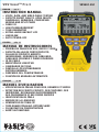 1
1
-
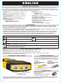 2
2
-
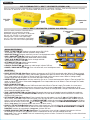 3
3
-
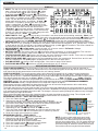 4
4
-
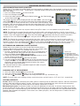 5
5
-
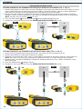 6
6
-
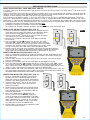 7
7
-
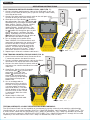 8
8
-
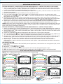 9
9
-
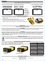 10
10
-
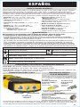 11
11
-
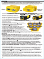 12
12
-
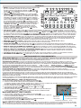 13
13
-
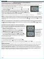 14
14
-
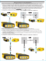 15
15
-
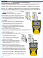 16
16
-
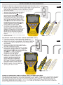 17
17
-
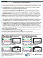 18
18
-
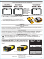 19
19
-
 20
20
-
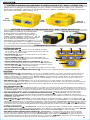 21
21
-
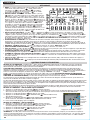 22
22
-
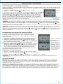 23
23
-
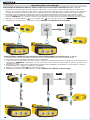 24
24
-
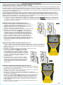 25
25
-
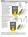 26
26
-
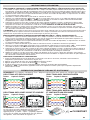 27
27
-
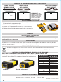 28
28


Klein Tools VDV501-851 VDV Scout PRO3 Manuel utilisateur
- Catégorie
- Testeurs de réseau câblé
- Taper
- Manuel utilisateur
dans d''autres langues
Documents connexes
-
Klein Tools VDV770-850 Manuel utilisateur
-
Klein Tools VDV770-850 Manuel utilisateur
-
Klein Tools VDV501-809 Mode d'emploi
-
-
Klein Tools VDV501-826 Mode d'emploi
-
Klein Tools VDV501-097 Mode d'emploi
-
Klein Tools VDV501-826 Manuel utilisateur
-
Klein Tools VDV500-705 Mode d'emploi
-
-
