
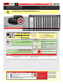
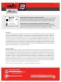
* HOOD PIN HOOD STATUS : THE HOOD PIN SWITCH MUST BE INSTALLED
IF THE VEHICLE CAN BE REMOTE STARTED WITH THE HOOD OPEN,
SET FUNCTION A11 TO OFF.
CONTACT
DE CAPOT
MANDATORY INSTALL | INSTALLATION OBLIGATOIRE Notice: the installation of safety
elements are mandatory. The hood pin
is an essential security element and
must be installed.
Notice: l'installation des éléments de
sécurité est obligatoire. Le contact de
capot est un élément de sécurité
essentiel et doit absolument être
installé.
THIS MODULE MUST BE INSTALLED BY A
QUALIFIED TECHNICIAN. A WRONG
CONNECTION CAN CAUSE PERMANENT
DAMAGE TO THE VEHICLE.
CE MODULE DOIT ÊTRE INSTALLÉ PAR
UN TECHNICIEN QUALIFIÉ, TOUTE
ERREUR DANS LES BRANCHEMENTS
PEUT OCCASIONNER DES DOMMAGES
PERMANENTS AU VÉHICULE.
STATUT DE CAPOT : LE CONTACT DE CAPOT, DOIT ÊTRE INSTALLÉ SI LE
VÉHICULE PEUT DÉMARRER À DISTANCE, LORSQUE LE CAPOT EST OUVERT,
PROGRAMMEZ LA FONCTION A11 À NON.
A11 OFF
NON
ADDENDUM - SUGGESTED WIRING CONFIGURATION
ADDENDA - SCHÉMA DE BRANCHEMENT SUGGÉRÉ
ALL REV.: 20230216
ONLY COMPATIBLE WITH AUTOMATIC TRANSMISSION VEHICLES.
COMPATIBLE AVEC VÉHICULE À TRANSMISSION AUTOMATIQUE SEULEMENT.
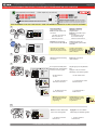
Supported functions & Function programming | Fonctions supportées et programmation des fonctions
ONLY COMPATIBLE WITH AUTOMATIC TRANSMISSION VEHICLES.
COMPATIBLE AVEC VÉHICULE À TRANSMISSION AUTOMATIQUE SEULEMENT.
Program bypass option:
Programmez l’option du contournement:
UNIT OPTION
OPTION UNITE DESCRIPTION
C1
OEM Remote status (Lock/Unlock)
monitoring
Suivi des status (Verrouillage/Déverrouil-
lage) de la télécommande d’origine
IF THE VEHICLE IS NOT EQUIPPED
WITH FUNCTIONAL HOOD PIN:
SI LE VÉHICULE N’EST PAS ÉQUIPÉ
D’UN CONTACT DE CAPOT FONCTIONNEL:A11 OFF
NON
Hood trigger (Output Status).
Contact de capot (état de sortie).
NOTES
The vehicles OEM remote will still operable
during remote start.
La télécommande d’origine du véhicule reste fonctionnel même si le
démarreur est engagé.
GUIDE # 106491
Vehicle functions supported in this diagram (functional if equipped) | Fonctions du
véhicule supportées dans ce diagramme (fonctionnelles si équipé)
VEHICLE
VEHICULES
YEARS
ANNÉES
Immobilizer bypass
Contournement
d’immobilisateur
Lock
Unlock
Arm
Disarm
Tachometer
Door Status
Trunk Status
Hood Status*
Hand-Brake Status
Foot-Brake Status
Active OEM Remote Start
FORD
Expedition
Push-to-Start
2022
•
•
•
•
•
•
•
•
•
•
•
•
PUSH
START
D6 Push-to-Start
Push-to-Start
MODEL: EVO-ALL
DATE:02/2019
FORTIN.CA
SN: 000000 00000
MADE IN CANADA
© 2018 ALL RIGHTS RESERVED 2019
COMPATIBLE
MODULE
REQUIRED:
QR CODE ON THE LABEL
FIRMWARE VERSION
VERSION LOGICIELLE
To add the rmware version and the options, use the
FLASH LINK UPDATER or FLASH LINK MOBILE tool,
sold separately.
Pour ajouter la version logicielle et les options,
utilisez l’outil FLASH LINK UPDATER
ou FLASH LINK MOBILE, vendu séparément.
MANUFACTURED AFTER:
2019
MODULE
COMPATIBLE
REQUIS:
CODE QR SUR ’ÉTIQUETTE 58.[02]
FABRIQUÉ APRÈS: 2019 MINIMUM
Contents
Supported functions & Function programming | Fonctions supportées et programmation des fonctions 1
Parts required - Stand Alone conguration - Remote Starter Functionnality - Remote Starter Functionality | Pièces Requises -
Conguration en démarreur à distance - Carte d'avertissement 2
Notes | Notes 3
Photo & Location | Photos & Emplacements 4
Connection Diagram - Transmission Automatic | Diagramme de Branchements - Automatique transmission 5
Key Bypass Programming Procedure | Procédure de Programmation Contournement de Clé 6
Remote starter functionality | Fonctionalité du démarreur à distance 9
Disclaimer | Avertissement 10
Page 1 / 10
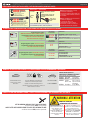
STAND ALONE INSTALLATION
INSTALLATION STAND ALONE

This guide may change without notice. See www.fortin.ca for latest version.
Ce guide peut faire l’objet de changement sans préavis. Voir www.fortin.ca pour la récente version.
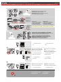
PARTS REQUIRED (NOT INCLUDED) | PIÈCES REQUISES (NON INCLUSES)
STAND ALONE CONFIGURATION | CONFIGURATION EN DÉMARREUR AUTONOME
OFF
ON
1x FLASH LINK UPDATER,
1x FLASH LINK MANAGER
1x FLASH LINK MOBILE
1x FLASH LINK MOBILE APP
OR
OU
1x
1x
HOOD PIN
VALET SWITCH
COMMUTATEUR
VALET
REMOTE START SAFETY OVERRIDE
SWITCH
CONTACT
DE
CAPOT
COMMUTATEUR DE SÉCURITÉ DE
DÉSACTIVATION DU DÉMARREUR
À DISTANCE
MANDATORY | OBLIGATOIRE Notice: the installation of safety
elements are mandatory.
The hood pin and the valet switch are
essential security elements and must
be installed.
Notice: l'installation des éléments de
sécurité est obligatoire.
Le contact de capot et le
commutateur de valet sont des
éléments de sécurité essentiels et
doivent absolument être installés.
Part #: RSPB available, Sold separately.
Pièce #: RSPB disponible, vendu séparément.
SOFTWARE | PROGRAMME
Smartphone AndroId or iOS with Internet
connection (provider charges may apply).
Téléphone Intelligent Android ou iOS
avec connection Internet (frais du
fournisseur Internet peuvent s’appliquer).
Microsoft Windows Computer
with Internet connection
Ordinateur Microsoft Windows
avec connection Internet
UN
Program bypass option
OEM Remote Stand Alone Remote Starter:
Programmez l’option du contournement
Démarreur à distance Autonome
avec télécommande d’origine :
D1.10
D1.1
By default, LOCK, LOCK, LOCK
Par défaut, VERROUILLE,VERROUILLE,VERROUILLE
LOCK, UNLOCK, LOCK
VERROUILLE,DÉVERROUILLE,VERROUILLE
OU
OR
UNIT OPTION
OPTION UNITE DESCRIPTION
UNIT OPTION
OPTION UNITE DESCRIPTION
D4
Hybrid mode
(Vehicle hybrid only)
Mode hybride
(vehicule hybride seulement)
Program bypass option with oem remote:
Programmez l’option du contournement
avec télécommande d'origine:
UNIT OPTION
OPTION UNITE DESCRIPTION
C1
OEM Remote Monitoring
Supervision de la
télécommande d'origine
Program bypass option with RF KIT antenna:
Programmez l’option du contournement
avec antenne RF:
Program bypass option
Vehicle hybrid only:
Programmez l’option du contournement
vehicule hybride seulement:
UNIT OPTION
OPTION UNITE DESCRIPTION
H1 to H6
H1 à H6
Supported RF Kits
and select RF Kit
Kit RF supportés
et sélectionnez le KIT RF
All doors must be closed.
Toutes les portes doivent
être fermées
Brake ON
No tach
Ignition
before start
Hood Open
Frein Activé
Pas de Tach
Clé de contact
détectée avant
démarrage
Capot Ouvert
REMOTE STARTER DIAGNOSTICS
DIAGNOSTIQUE DU DÉMARREUR À DISTANCE
MODULE RED LED | DEL ROUGE DU MODULE
x2 ash :
x3 ash :
x4 ash :
x5 ash :
The vehicle will START.
Le véhicule DÉMARRE.
START
3X
Press the OEM remote’s Lock button 3x to
remote-start (or remote-stop) the vehicle.
Appuyez sur le bouton Verrouillage 3X de la
télécommande d'origine pour démarrer à distance (ou
arrêter à distance) le véhicule.
REMOTE STARTER FUNCTIONALITY | FONCTIONNALITÉS DU DÉMARREUR À DISTANCE
REMOTE STARTER WARNING CARD | CARTE D'AVERTISSEMENT DE DÉMARREUR À DISTANCE
CUT THIS WARNING CARD AND STICK IT ON A VISIBLE PLACE:
or use the package RSPB, Sold separately.
COUPEZ CETTE CARTE D'AVERTISSEMENT ET COLLEZ-LA À UN ENDROIT VISIBLE:
ou utilisez la trousse RSPB, vendue séparément.
THE VEHICLE CAN BE STARTED BY
EITHER: PRESSING THE LOCK BUTTON
ON THE OEM REMOTE 3 TIMES
CONSECUTIVELY OR BY A
SMARTPHONE. TURN ON THE SAFETY
SWITCH LOCATED UNDER THE
DASHBOARD BEFORE WORKING ON
THE VEHICLE.
LE VÉHICULE PEUT DÉMARRER SOIT: EN
APPUYANT 3 FOIS CONSÉCUTIVEMENT SUR
LE BOUTON VERROUILLAGE DE LA
TÉLÉCOMMANDE DU VÉHICULE OU PAR UN
TÉLÉPHONE INTELLIGENT. ACTIONNEZ EN
POSITION ‘ON’ LE COMMUTATEUR DE
SÉCURITÉ SITUÉ SOUS LE TABLEAU DE BORD
AVANT LES TRAVAUX D'ENTRETIEN.
DÉMARREUR À DISTANCE
REMOTE STARTER
WARNING | ATTENTION
Parts required - Stand Alone conguration - Remote Starter Functionnality - Remote Starter Functionality | Pièces
Requises - Conguration en démarreur à distance - Carte d'avertissement
Page 2 / 10

This guide may change without notice. See www.fortin.ca for latest version.
Ce guide peut faire l’objet de changement sans préavis. Voir www.fortin.ca pour la récente version.
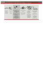
NOTES
LE DÉMARREUR NE FONCTIONNERA PAS SI :
Hood is open
or switch is not present
Le capot est ouvert
ou le capteur
n'est pas présent
Check Engine light is ON
La lumière Check Engine
est allumée
Low fuel light is ON
La lumière
Low Fuel est
allumée
Vehicle battery voltage
is too low
Le voltage
de la batterie
est trop bas.
THE REMOTE START WILL NOT OPERATE IF :
ATTENTION
CAUTION
To use the remote again ignition must be
turned ON and OFF.
Pour utiliser le démarreur à distance de
nouveau l'ignition doit être allumée puis éteinte.
ON OFF
The remote start is limited to two
consecutive command Start or Stop.
Le démarreur à distance est limité à deux
commandes consécutives
Démarrage ou Arrêt.
START
or
STOP
START
or
STOP
Notes | Notes
Page 3 / 10

This guide may change without notice. See www.fortin.ca for latest version.
Ce guide peut faire l’objet de changement sans préavis. Voir www.fortin.ca pour la récente version.
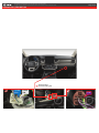
DESCRIPTION | DESCRIPTION
(~)CAN2
LOW
(~)CAN2
HIGH (+)12V
1A
A
1B
B
Behind glovebox
Derrière la boîte à gants
Photo & Location | Photos & Emplacements
Page 4 / 10

This guide may change without notice. See www.fortin.ca for latest version.
Ce guide peut faire l’objet de changement sans préavis. Voir www.fortin.ca pour la récente version.
Yellow In A1
Purple In A2
Purple/White In A3
Green Out A4
White Out A5
Orange In A6
Orange/Black In A7
Dk.Blue In A8
Red/Blue In A9
Lt.Blue/Black A10
Black Out A11
Pink Out A12
Yellow/Black In A13
Brown/White Out A14
Pink/Black Out A15
Purple/Yellow A16
Green/White A17
Green/Red A18
White/Black A19
Lt.Blue A20
C5 Brown
C4 Gray/Black
C3 Gray
C2 Orange/Brown
C1 Orange/Green
D6 White/Red
D5 White/Blue
D4 White/Green
D3 Yellow/Red
D2 Yellow/Blue
D1 Yellow/Green
AC
D
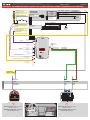
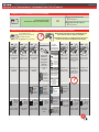
AUTOMATIC TRANSMISSION WIRING CONNECTION | SCHÉMA DE BRANCHEMENT TRANSMISSION AUTOMATIQUE
A2
A3
A4
A5
A6
A7
A8
A9
A10
A11
A12
A13
A14
A15
A16
A17
A18
A19
A20
C5
C4
C3
C2
C1
D6
D5
D4
D3
D2
D1
A1
D2
D3
D4
D5
D6
C3
C4
C5
A20
A19
A18
A17
A15
A14
A12
A11
A10
A9
A7
A6
A5
A4
A1 B
RS1 Ground | Masse
Ground
Masse
RS2 IN 12V Battery(+)
WITH | AVEC DATA-LINK:
Direct connection
Branchement directe
RF-KIT REMOTE
STARTER
KIT-RF DÉMARREUR
À DISTANCE
WITH RF-KIT
AVEC KIT RF
OPTIONAL RF-KIT
KIT RF OPTIONNEL
B4
B3
B2
B1
Cut | Coupez Red
Cut | Coupez Black
Blue
White
WITHOUT RF-KIT
SANS KIT RF
B4 Red12V Battery(+)
B3 BlackGround | Masse
Ground
Masse
(-) Unlock
(-) Lock
(-) Lock/Unlock input external
control | Contrôle du
(-) verrouillage devérrouillage
entrée externe
Start / Stop external control
Contrôle de démarrage/arrêt
externe
Start/Stop external
Hood pin
Hood pin only required on vehicles not
equipped with a factory hood pin.
Commutateur de capot requis seulement
si le véhicule n'est pas équipé de cette
composante.
SAFETY OVERRIDE SWITCH
COMMUTATEUR DE SÉCURITÉ
Connection Diagram - Transmission Automatic | Diagramme de Branchements - Automatique transmission
EXPEDITION
Convenient Igni�on OUT
RS3 IN/OUT (+)Igni�on Can be required
Peux être requis
A16
CAN 2 LOW
CAN 2 HIGH
C2
C1
7.5Amp Fuse
Fusible 7.5 AMP
B4 or RS2
Behind glove box - Back view, 30-pin
White connector.
Derrière le coffre à gants. Vue de dos,
connector Blanc de 30-pin.
Behind glove box - Back view, 17-pin
Brown connector.
Derrière le coffre à gants. Vue de dos,
connector Brun de 17-pin.
24
15 16
23 26
17 18
25 28
19 20
27 30
21 22
29
123
7 8 9 10
456
11 12 13 14
CAN2 HIGH CAN2 LOW
Blue White
Bleu Blanc
1A
1B
10
4567
8 9
171614 15
1312
11
123
(+)12V
Purple/Red
Mauve/Roude
Guide # 100721 Page 5 / 10

CONTINUED NEXT PAGE | CONTINUEZ À LA PAGE SUIVANTE
4
5
The RED and YELLOW
LEDs alternate.
Les DELs ROUGE et
JAUNE alternent.
Release the programming
button when the LED is BLUE.
2
1
3
Relâchez le bouton de
programmation quand la DEL
est BLEU.
Insert the required remaining
connectors. Insérez les connecteurs
requis restants.
x1
HOLD
Press and hold
Insert
the
programming button:
the 4-Pin (Data-Link)
connector.
Appuyez maintenir
enfoncé
Insérez
et
le bouton de
programmation:
le connecteur 4 pins
(Data-Link)
The Blue, Red, Yellow and
Blue & Red LEDs will
alternatively illuminate.
Les DELs Bleue, Rouge,
Jaune et Bleue & Rouge
s'allumeront alternativement.
RELEASE
If the LED is not solid BLUE
disconnect the 4-Pin connector
(Data-Link) and go back to step 1.
ON BLUE
BLEU
Si le DEL n'est pas BLEU
débranchez le connecteur 4
pins (Data-Link) et allez au
début de l'étape 1.
Make sure that the DELs are
flashing RED and YELLOW
before continuing
programming.
Assurez-vous que les DELs
clignotent ROUGE et JAUNE
avant de poursuivre la
programmation.
OFF
The BLUE LED will
turn OFF.
La DEL
BLEUE s’éteint.
IGNITION ONIGNITIONOFF
OFF
IGNITION OFF
ON
The RED and YELLOW
LEDs will alternated.
Les DELs ROUGE et
JAUNE alternent.
The BLUE, YELLOW and
RED LEDs will alternated.
Les DELs BLEUE, JAUNE
et ROUGE alternent.
ALTERNATE
ALTERNATE
OFF
IGN ON
x1
PRESS
Do not press the brake pedal.
Press the Push-to-Start button
once to turn on the ignition.
Ne pas appuyer sur la pédale de
frein.
Appuyez 1 fois sur le bouton
démarrage. pour allumer l’ignition.
OFF
x1
PRESS
Press the Push-to-Start button
once to turn off the ignition.
Appuyez 1 fois sur le bouton
démarrage pour éteindre l'ignition.
5-Prog.5-9-DCYPTOR-PTS-1.2
This guide may change without notice. See www.fortin.ca for latest version.
Ce guide peut faire l’objet de changement sans préavis. Voir www.fortin.ca pour la récente version.
DCRYPTOR PROGRAMMING PROCEDURE | PROCÉDURE DE PROGRAMMATION AVEC DCRYPTOR
Parts required (not included) Pièces requises (non incluses)
1x FLASH LINK UPDATER,
1x FLASH LINK MANAGER
1x FLASH LINK MOBILE
1x FLASH LINK MOBILE APP
SOFTWARE | PROGRAMME
Smartphone Android or iOS with Internet connection
(Internet provider charges may apply)
Téléphone Intelligent Android ou iOS avec connection
Internet (des frais du fournisseur Internet peuvent s’appliquer)
OR
OU
Microsoft Windows Computer with Internet connection
Ordinateur Microsoft Windows avec connection Internet
1x1x
BEFORE PROGRAMMING SET THE UNIT OPTIONS AND SAVE. | AVANT LA PROGRAMMATION CONFIGURER LES OPTIONS DE L'UNITÉ ET SAUVEGARDER.
Key Bypass Programming Procedure | Procédure de Programmation Contournement de Clé
Page 6 / 10

The module is now
programmed.
Le module est
programmé.
9
10
IGNITION ON IGNITION OFF
IGNITION ONIGNITIONOFF
OFF
ON
ON
The module is now
programmed.
Le module est
programmé.
The BLUE LED will turn
ON.
La DEL BLEUE s’allume
solide .
ON
ALTERNATE
The BLUE LED will
flash rapidly.
La DEL BLEUE
clignotera rapidement.
FLASH
RAPIDLY
The BLUE will turn OFF. La DEL BLEUE s’éteint.
IGN ON
x1
PRESS
Do not press the brake pedal.
Press the Push-to-Start button
once to turn on the ignition.
Ne pas appuyer sur la pédale de
frein.
Appuyez 1 fois sur le bouton
démarrage. pour allumer l’ignition.
OFF
x1
PRESS
Press the Push-to-Start button
once to turn off the ignition.
Appuyez 1 fois sur le bouton
démarrage pour éteindre l'ignition.
The BLUE, YELLOW and
RED LEDs will alternated.
Les DELs BLEUE, JAUNE
et ROUGE alternent.
5-Prog.5-9-DCYPTOR-PTS-2.2
EVO-ALL
Disconnect all the connectors and after
the Data-Link (4-pins) connector.
Débranchez tous les connecteurs et ensuite
le connecteur Data-Link (4-pins).
*Pièces requises (non incluses)
Use the tool:
FLASH LINK UPDATER or
FLASH LINK MOBILE
to visit the DCryptor menu.
Utilisez l'outil:
FLASH LINK UPDATER ou
FLASH LINK MOBILE
pour visiter le menu DCryptor.
*Parts required (not included)
FLASH LINK UPDATER*
FLASH LINK MOBILE*
FLASH LINK MANAGER*
SOFTWARE | PROGRAMME
Microsoft Windows
Computer with
Internet connection*
Ordinateur Microsoft
Windows avec
connection Internet*
VEHICLE'S OBDII
CONNECTOR
CONNECTEUR OBDII
DU VÉHICULE
OR
OU
Smartphone*
(Internet provider
charges
may apply)
Téléphone
Intelligent*
(des frais du
fournisseur
Internet peuvent
s’appliquer)
AFTER DCRYPTOR PROGRAMMING COMPLETED
Go back to the vehicle and reconnect the 4-Pin (Data-Link)
connector and after, all the remaining connector.
APRÈS LA PROCÉDURE DE PROGRAMMATION
DCRYPTOR COMPLETÉE : retournez au véhicule et
rebranchez le connecteur 4-pins (Data-Link)
et après, tous les connecteurs du EVO-ALL.
EVO-ALL
6
7
8
This guide may change without notice. See www.fortin.ca for latest version.
Ce guide peut faire l’objet de changement sans préavis. Voir www.fortin.ca pour la récente version.
KEY BYPASS PROGRAMMING PROCEDURE 2/2 | PROCÉDURE DE PROGRAMMATION CONTOURNEMENT DE CLÉ 2/2
Page 7 / 10

OPTIONAL FORTIN RF KIT SERIES 4 OR SERIES 9 PROGRAMMING | PROGRAMMATION DU KIT RF FORITN SÉRIE 4 OU SÉRIE 9 (OPTIONNELLE)
Program bypass option:
Programmez l’option du contournement : H2
☑Supported RF-KITS enable
☑ H2 Fortin 2
☑Activation KITS RF supporté
☑ H2 Fortin 2
PROGRAM BYPASS OPTION | PROGRAMMATION DES OPTIONS DE CONTOURNEMENT
x4
PRESS
The module must be
programmed on the vehicle.
Le module doit être
programmé sur le véhicule.
MAKE SURE THE IGNITION KEY HAS BEEN IN THE
OFF POSITION FOR AT LEAST 5 SECONDS.
ASSUREZ-VOUS QUE LA CLÉ DE CONTACT EST À LA
POSITION OFF DEPUIS AU MOINS 5 SECONDES.
Press and
release the
brake pedal
four times.
Appuyez et
relâchez
quatre fois
la pédale de
frein.
The LED will
turn ON
solide.
Le témoin
s’allumera.
The LED
will flash
rapidly.
Le témoin
clignotera
rapidement.
The LED
will turn off
each time.
Le témoin
s’inteindra
chaque fois
The LED
will turn Off.
The 3
LED will
turn ON
solid.
Les 3 DELs
s’allumeront
solide.
The
YELLOW
LED will
turn ON
solid.
La DEL JAUNE
s’allumera solide.
The
YELLOW
LED will
turn ON
solid.
La DEL JAUNE
s’allumera solide.
The
YELLOW
LED will
turn Off.
La DEL JAUNE
s’éteindra.
The
YELLOW
LED will
turn Off.
La DEL JAUNE
s’éteindra.
The LED will
flash rapidly.
Le témoin
clignotera
rapidement.
The 3 LED
will turn off
each time.
Les 3 DELs
s’éteindront
chaque fois.
Le témoin
s’éteint
The 3 LED
will turn off.
Les 3 DELs
s’éteindront.
SUR CHACUNE DES
TÉLÉCOMMANDES
ON EACH
TRANSMITTER
The
YELLOW
LED will
turn ON
solid.
La DEL JAUNE
s’allumera solide.
OFF OFF OFFON ONON 4X BRAKES
1 2 53 6 7 84
4 BUTTONS
4 BOUTONS
1 BUTTON
1 BOUTON
PRESS APPROX.
12 SEC. AND WAIT
FOR THE BLUE LED
TO TURN OFF THEN
BACK ON SOLID
THEN RELEASE.
PRESS AND
RELEASE
APPUYEZ ET
RELÂCHEZ
PRESS AND
RELEASE
APPUYEZ ET
RELÂCHEZ
APPUYEZ ET TENEZ
ENFONCÉ LE POUR
APPROX. 12 SEC, LA
DEL BLEUE
S'ÉTEINT ET
S'ALLUME SOLIDE,
ENSUITE
RELÂCHEZ.
The LED will
turn off each
time.
Le témoin
s’éteindra
chaque fois.
Turn the key to
the ON/RUN
position.
Turn the
ignition to the
OFF position.
Tournez la clé
à la position
ON/RUN.
Tournez la clé
à la position
ARRÊT (OFF).
IGN
TURN
ON/RUN
Turn the key to
the ON/RUN
position.
Tournez la clé
à la position
ON/RUN.
IGN
TURN
ON/RUN
Turn the key to
the ON/RUN
position and
leave it ON for
5 sec.
Tournez la clé
à la position
ON/RUN et
laissez à ON
pour 5 sec.
IGN
TURN
ON/RUN
PUSH
OFF
TURN
OFF
Turn the
ignition to the
OFF position.
Tournez la clé
à la position
ARRÊT (OFF).
PUSH
OFF
TURN
OFF
Turn the
ignition to the
OFF position.
Tournez la clé
à la position
ARRÊT (OFF).
PUSH
OFF
TURN
OFF
5-STANDALONE_RFKIT
This guide may change without notice. See www.fortin.ca for latest version.
Ce guide peut faire l’objet de changement sans préavis. Voir www.fortin.ca pour la récente version.
OPTIONAL RF-KIT PROGRAMMING | PROGRAMMATION KIT RF OPTIONELLE
Page 8 / 10

Remote start the
vehicle.
Démarrez à
distance.
All doors must
be closed.
Toutes les
portes doivent
être fermées
Press the brake pedal.
The vehicle can now be
put in to gear and
driven.
If the Smart-Key is not detected
the vehicle will shut down.
Appuyez sur la pédale de
frein.
Vous êtes maintenant
prêt à embrayer et
prendre la route.
Si la clé intelligente n'est pas
détectées le véhicule s'éteindra.
ON
x1
PRESS
DO NOT PRESS THE
BRAKE PEDAL.
Press and release
the Push-to-Start
button once.
NE PAS APPUYER LA
PÉDALE DE FREIN.
Appuyez et relâchez
une fois le bouton
démarrage
(Push-to-Start.
Start
Enter the vehicle with the
SMART-KEY.
Entrez dans le véhicule
avec la clé intelligente
(SMART-Key) sur vous
UNLOCK
Unlock the doors with
either:
• The OEM remote
• The remote-starter
remote
• Or the proximity remote
Déverrouillez les portes
avec soit:
• la télécommande
d'origine
• la télécomande du
démarreur à distance
• ou la télécommande de
proximté.
This guide may change without notice. See www.fortin.ca for latest version.
Ce guide peut faire l’objet de changement sans préavis. Voir www.fortin.ca pour la récente version.
REMOTE STARTER FUNCTIONALITY | FONCTIONNALITÉS DU DÉMARREUR À DISTANCE
Remote starter functionality | Fonctionalité du démarreur à distance
Page 9 / 10

ALL
MODEL: EVO-ALL
DATE:02/2019
FORTIN.CA
SN: 000000 00000
MADE IN CANADA
© 2018 ALL RIGHTS RESERVED
Module label | Étiquette sur le module
Notice: Updated Firmware and Installation Guides
Updated fi rmware and installation guides are posted on our web site on a regular
basis. We recommend that you update this module to the latest fi rmware and
download the latest installation guide(s) prior to the installation of this product.
Notice: Mise à jour microprogramme et Guides d’installations
Des mises à jour du Firmware (microprogramme) et des guides d’installation
sont mis en ligne régulièrement. Vérifi ez que vous avez bien la dernière version
logiciel et le dernier guide d’installation avant l’installation de ce produit.
WARNING
The information on this sheet is provided on an (as is) basis with no representation or warranty of accuracy whatsoever.
It is the sole responsibility of the installer to check and verify any circuit before connecting to it. Only a computer safe
logic probe or digital multimeter should be used. FORTIN ELECTRONIC SYSTEMS assumes absolutely no liability or
responsibility whatsoever pertaining to the accuracy or currency of the information supplied. The installation in every case
is the sole responsibility of the installer performing the work and FORTIN ELECTRONIC SYSTEMS assumes no liability
or responsibility whatsoever resulting from any type of installation, whether performed properly, improperly or any other
way. Neither the manufacturer or distributor of this module is responsible of damages of any kind indirectly or directly
caused by this module, except for the replacement of this module in case of manufacturing defects. This module must be
installed by qualifi ed technician. The information supplied is a guide only. This instruction guide may change without
notice. Visit www.fortinbypass.com to get the latest version.
MISE EN GARDE
L’information de ce guide est fournie sur la base de représentation (telle quelle) sans aucune garantie de précision et
d’exactitude. Il est de la seule responsabilité de l’installateur de vérifi er tous les fi ls et circuits avant d’effectuer les connexions.
Seuls une sonde logique ou un multimètre digital doivent être utilisés. FORTIN SYSTÈMES ÉLECTRONIQUES n’assume
aucune responsabilité de l’exactitude de l’information fournie. L’installation (dans chaque cas) est la responsabilité de
l’installateur effectuant le travail. FORTIN SYSTÈMES ÉLECTRONIQUES n’assume aucune responsabilité suite à
l’installation, que celle-ci soit bonne, mauvaise ou de n’importe autre type. Ni le manufacturier, ni le distributeur ne se
considèrent responsables des dommages causés ou ayant pu être causés, indirectement ou directement, par ce module,
excepté le remplacement de ce module en cas de défectuosité de fabrication. Ce module doit être installé par un technicien
qualifi é. L’information fournie dans ce guide est une suggestion. Ce guide d’instruction peut faire l’objet de changement
sans préavis. Consultez le www.fortinbypass.com pour voir la plus récente version.
Copyright © 2006-2019, FORTIN AUTO RADIO INC ALL RIGHTS RESERVED PATENT PENDING
TECH SUPPORT
Tél: 514-255-HELP (4357)
1-877-336-7797
ADDENDUM GUIDE WEB UPDATE | MISE À JOUR INTERNET
www.fortinbypass.com
Disclaimer | Avertissement
Page 10 / 10
-
 1
1
-
 2
2
-
 3
3
-
 4
4
-
 5
5
-
 6
6
-
 7
7
-
 8
8
-
 9
9
-
 10
10


dans d''autres langues
- English: Fortin 106491 Installation guide
Documents connexes
-
Fortin EVO ALL HAR-VW2 Electrical Wiring Manual
-
Fortin 97331 EVO-ALL Guide d'installation
-
Fortin 2021 Guide d'installation
-
Fortin 103031 2021 Chrysler 300 Push Button Remote Starters and Alarm Systems Guide d'installation
-
Fortin EVO-ONE Volkswagen Golf 2016 Guide d'installation
-
Fortin 2017 Guide d'installation
-
Fortin 67901 EVO-ALL Guide d'installation
-
Fortin 94421 Guide d'installation
-
Fortin 97391 Guide d'installation
-
Fortin 111601 Guide d'installation