
ENGLISH
GB
ITALIANO
I
FRANÇAIS
F
ESPAÑOL
E
DEUTSCH
D
Quick guide
Guida rapida
Guide rapide
Manual de istrucciones rapide
Handbuch
VX2000
Multiprotocol Interface Option


ENGLISH
GB
VX2000
MULTIPROTOCOL
INTERFACE
D2000PRO OPTION
USER’S MANUAL
The information contained in this document is the
property of Aethra
. It is subject to change without
notice and it shall in no way be blinding for
Aethra
2002 Copyright Aethra S.p.a. All right reserved.
Release 3/2.62 – December 2002
Code 074042002ML
This manual is composed of 18 pages


Quick Guide VX2000
5
GB
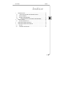
Index
1 INTRODUCTION.................................................................................... 7
1.1 OPENING THE MANUAL TEST SCREEN ....................................... 7
1.2 COMMON SETUP ............................................................................. 8
1.3 UNFRAMED BER TEST .................................................................... 10
1.3.1 RUNNING AN UNFRAMED BER TEST...................................... 11
2 SMART STATUS.................................................................................... 13
2.1 V/X INTERFACE STATUS................................................................. 13
3 TECHNICAL SPECIFICATIONS ............................................................ 13
4 FUNCTIONAL SPECIFICATIONS.......................................................... 16
4.1 PIN OUT ............................................................................................ 17
4.2 OPTIONAL CODES........................................................................... 20

Quick Guide VX2000
6
GB
SAFETY RULES
The change from cold to hot environments can cause the formation of
condense inside the device. To avoid malfunctioning, wait at least 2 hours
before connecting the device to the supply mains.
Do not access internal parts of the device (and/or of the power supply unit).
If objects or liquids penetrate inside the device, immediately disconnect the
power supply cable. Before using the device again, have it checked by
specialised staff.
Refer to qualified staff for service.
In case of intervention, always check that the power supply has been
completely and successfully disconnected.
In case of fire, absolutely avoid using water to extinguish it.
WARNINGS
ATTENTION:
Many of the components used in this device are sensitive to
electrostatic charge.
In case of manipulation of the connection cables, disconnect the
power supply and avoid direct contacts with the connector terminals.
When handling electronic components, to eliminate any static
electricity touch a grounded surface. If possible, wear a grounding
armband.
Failure to comply with these warnings could cause permanent
damage to device.
To guarantee continuous protection for operator safety, only use the
mains adapter supplied with the instrument.

Quick Guide VX2000
7
GB
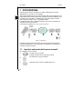
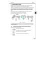
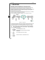
1 INTRODUCTION
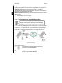
With the VX2000 option, the D2000Pro is able to perform tests over WAN/datacom
lines with a bit rate up to 2.048 Mbit/s.
Thanks to the possibility to emulate both DTE (Data Terminal Equipment) and DCE
(Data Communications Equipment), the D2000Pro allows to carry out quality tests,
bit error rate (BER), in end-to-end mode over datacom line, or checks toward the
User’s DTE (CSU, router, or other WAN equipment).
The criteria monitoring and the possibility to manage local loops (LL), allow to
extend controls over datacom line.
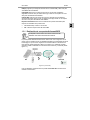
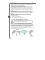
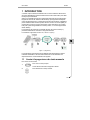
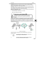
The interfaces supported are: V.35, V.36 and V.11 (X.21),
Fig. 1-1 (single end)
The following paragraphs refer to various tests available using the D2000Pro
interface, further information about the D2000Pro are available in the User’s Manual
of the device.
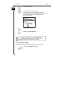
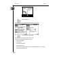
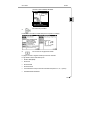
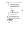
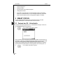
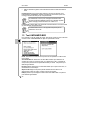
1.1 Opening the Manual Test Screen
To select the manual test:
1
Open the TEST MENU.
The last used setup appears on the screen.
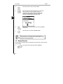
2
Select the ACCESS field.
3
Select the type of access, V/X INTERFACE.

Quick Guide VX2000
8
GB
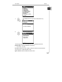
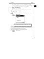
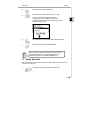
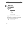
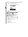
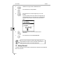
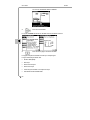
4
Select the ACT AS field.
5
Select the instrument mode, e.g. DTE.
The lower section of the screen shows the selected
network configuration. The yellow LED that corresponds to
the selected mode goes on.. It’s possible to choose
between DTE and DCE
6
Select MANUAL TESTS.
7
Select the test UNFRAMED BER.
In order to connect to the line, use the appropriate cable
according to the selected mode. In case of DCE mode, an
appropriate cable, to order separately, is needed.
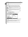
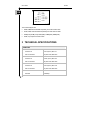
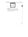
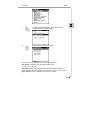
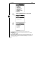
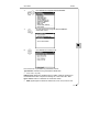
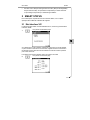
1.2 Common Setup
This page is used to setup the common parameters for the various tests.
1
To select the COMMON SETUP page

Quick Guide VX2000
9
GB
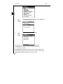
1
The COMMON SETUP page can be selected from any
test
2
Choose the desired field
The following parameters can be defined for the V/X INTERFACE access:
Interface type: Choose the interface to use among:
• V.35, V.36, V.11 (X.21)
Line rate: Select the line rate, in Kbit/s, used by the device to transmit the data.
Only if Clock TX = Inside and mode = DCE
Ignore criteria: Enable or disable the criteria control

Quick Guide VX2000
10
GB
• NO, the device guarantees and controls the C108, C107, C105, C106 and C109i
criteria
• YES, the management and the check of these criteria, between DTE and DCE, is
disabled
Clock RX: Define the type of clock used to receive data; with CLOCK RX:
LOOPED, the device samples data received with the clock coming from DTE
(C113). Only DCE.
In DCE mode, the clock TX is fixed at “INSIDE”, whereas in DTE
mode, the device uses the clock coming from the DCE over
C114 criterion.
Loop3 (C141): Set “YES” to ask the DCE to perform a local loop (LL) of the data.
Only DTE.
The LL (local loop) request is supported by V.35 and V.36
interfaces only.
1.3 UNFRAMED BER Test
In order to run a line quality test, select from the manual test menu, the
UNFRAMED BER and set the following parameters:
Duration: Choose the duration of the test. Select from the defined list or define your
own duration
Pass/Fail test: Choose the BER value. This value is used to determine the pass or
fail test condition. Selecting G.821, the result is compared with the quality
performance required by G.821. Only for line rate 64Kbit/s.
Error injection: Choose the BER value used for manual or automatic bit error
injection
Bit sequence: Set the pseudo-random pattern to be used. Select from the list

Quick Guide VX2000
11
GB
HRX(%): Enter the variation percentage for the DM and SES thresholds. Only for 1
channel bandwidth
DM Threshold: Choose the number of errors per minute to consider it as degraded.
Use the G.821 (4) default value when no other value is preferred. Only for line rate
64Kbit/s
SES Threshold: Choose the number of errors per second to be considered as
severely errored. Use the G.821 (64) default value when no other value is preferred.
Only for line rate 64Kbit/s
Auto print: Choose the autoprint condition for the test results between:
• Time interval: every 15 or 30 minutes
• DM: when the DM threshold value is exceeded
1.3.1 Running an Unframed BER Test
VX2000 adapter is fed directly by the D2000Pro, this cause a
decrease of the battery duration.
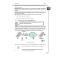
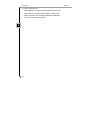
The test can be carried out both end-to-end and single end mode. In the first case is
necessary to put another D2000Pro/VX2000 at the remote end of the line (fig. 1-2).
In single-end mode, is necessary to carry out a loop over the line. The loop can be
request to DCE with C141 criterion, through a specific command given to the DCE
or carrying out a physical loop between TX side and RX side (see figure 1-1).
Fig. 1-2 (end-to-end)
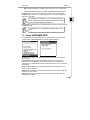
When you have defined the setup for the Unframed BER test, continue as follows:
1
Select ‘Use this setup for testing’ in the first SETUP page.
2
Connect the instrument as displayed on the screen and
press the RIGHT CURSOR key.

Quick Guide VX2000
12
GB
3
Start the BER test.
The LED RUN goes on and the test results appear on the screen.
4
Scroll through the result pages.
The pages show the following results for each call:
The status line indicates the status of the test.
• Bit Error Rate (BER)
• Received bits
• Errored bits transmitted
• Errored bits received
• Synchronization and time without synchronization expressed in h, m, s (S-loss).
• Result of the PASS/FAIL test

Quick Guide VX2000
13
GB
• G.821 data: SES (severely errored seconds), DM (degraded minutes), ES
(errored seconds), US (unavailable seconds) in absolute value and percentage,
result of the PASS/FAIL test according the G.821 quality targets.
2 SMART STATUS
To have a complete description of the Smart Status feature, see the specific
chapter in the D2000Pro User’s Manual.
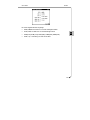
2.1 V/X Interface status
The 2
nd
page, relative to V/X INTERFACE access, shows the activity of the used
interface.
1
Goes to page 2.
The Clock Rx value, is displayed on the Status pages only if the
clock value has been set as ‘Looped’, in the common setup.
Selecting the relative interface field and pushing ENTER, it is possible to insert a
loop on the data, the device will send, in transmission, the data received from the
remote. Perform the same operation to remove the loop.
The 3
rd
page shows the state of criteria toward DCE and DTE
2
Goes to page 3.

Quick Guide VX2000
14
GB
The criteria displayed are:
• C103, C104, data transmitted respectively from DTE and from DCE
• C113, C115, clock transmitted respectively from DTE and from DCE
• C105 (RTS), C106 (CTS), C107 (DSR), C108 (DTR), C109 (DCD)
• C141, loop request from DTE to DCE
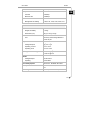
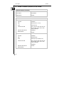
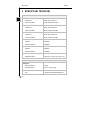
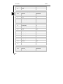
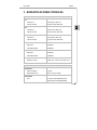
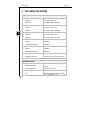
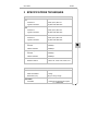
3 TECHNICAL SPECIFICATIONS
INTERFACES
V.11
Conforms at
User’s connection
CCITT (ITU-T) Rec.V.11
15 poles male, ISO 4903
V.35
Conforms at
User’s connection
CCITT (ITU-T) Rec.V35
34 poles male, ISO 2593
V.36
Conforms at
User’s connection
CCITT (ITU-T) Rec.V.36
37 poles male, ISO 4902
Transmission Clock
Structure
N*64Kbps

Quick Guide VX2000
15
GB
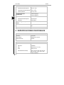
Maximum rate 2.048Kbps
Reception Clock
Structure
Maximum rate
N*64Kbps
2.048Kbps
Criteria
Management and reading
C108, C107, C105, C106, C109, C141
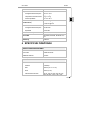
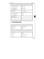
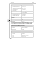
ENVIRONMENTAL CHARACTERISTICS
Dimension
Weight, with battery
Dimensions (mm)
≅ 200 gr.
84 (w) x 150 (l) x 32 (d)
Power
Hint
Accessory is feed through D2000
PRO
power out port
Temperature
Storage/Transport
Operating, nominal
Operating, limits
-40
o
C to +70
o
C
-5
o
C to +45
o
C
-10
o
C to +55
o
C
Humidity, non-condensing
≤ 93% RH @ 40
o
C
≤ 70% RH @ 55
o
C
Altitude
Storage/transport
Operating
12,000 meters
4,500 meters
User's Safety Aspects
EN 61010-1, EN 60950, EN 41003
EMC Aspects
EN 55022, EN 55024, EN 61000-3-2 / -
3-3
CE Marking
Class B (residential devices)

Quick Guide VX2000
16
GB
4 FUNCTIONAL SPECIFICATIONS
OPERATING MODES AVAILABLE
Simulation
Ignore criteria
Mode selection
DTE, DCE
User defined
Runtime
USER’S BIT RATE
Transmission Clock
Structure
DTE
DCE
Internal clock rates
External maximum rate
Mode selection
N*64Kbps
External (C114 -> C113)
Internal (C115)
48, 64, 128, 192, 256, 320, 384, 512,
640, 768, 960, 1.024, 1.280, 1.536,
1.920, 2.048 Kbps
2.048Kbps
Runtime
Reception Clock
Structure
DTE
DCE
Internal clock rates
External maximum rate
Mode selection
N*64Kbps
External (C115)
Internal (C114), Looped (C113)
48, 64, 128, 192, 256, 320, 384, 512,
640, 768, 960, 1.024, 1.280, 1.536,
1.920, 2.048 Kbps
2.048Kbps
Runtime

Quick Guide VX2000
17
GB
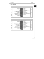
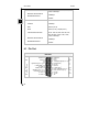
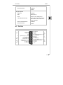
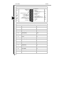
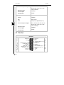
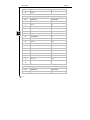
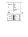
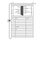
4.1 Pin Out
DTE Mode
DCE Mode
1 - Nc
2 - C113A
3 - C115B
4 - C105
,
Control A
(
V.11
)
5 - C106
,
Indication A
(
V.11
)
6 - C103A
(
TxA
1
)
7 - Ground
8 - C114A
9 - C104A
(
RxA
1
)
10 - C109 Byte timing B (V.11)
12 - C107
11 - C141
13 - Reserved
In
Out
-
C113B -14
Out
In
Out
Out
In
In
In
In
-
Out
C115A -15
Control B
(
V.11
)
-16
Indication B
(
V.11
)
-17
C103B
(
TxB
1
)
-18
C114B -19
C104B
(
RxB
1
)
-20
Byte timinig A (V.11) -21
22
23
C108 -24
Ground -25
Out
Out
Out
In
In
In
In
In
-
-
1 - Nc
2 - C114A
3 - C115B
4 - C106
,
Indication A
(
V.11
)
5 - C105
,
Control A
(
V.11
)
6 - C104A
(
TxA
1
)
7 - Ground
8 - C115A
9 - C103A
(
RxA
1
)
10 - C109 Byte timing B (V.11)
12 - C108
11 - Reserved
13 - Reserved
Out
Out
-
C114B -14
Out
Out
Out
Out
In
Out
In
Out
-
Out
C115A -15
Indication B
(
V.11
)
-16
Control B
(
V.11
)
-17
C104B
(
TxB
1
)
-18
C115B -19
C103B
(
RxB
1
)
-20
Byte timinig A (V.11) -21
22
23
C107 -24
Ground -25
Out
Out
-
In
Out
In
Out
In
-
-

Quick Guide VX2000
18
GB
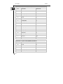
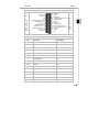
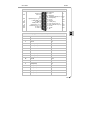
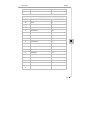
X.21bis/V.35 - 34 poles socket (ISO2593) – DTE mode
PIN CRITERION DIRECTION
AA C114B In
Y C114A In
S C103B (TxB1) Out
P C103A (TxA1) Out
X C115B In
V C115A In
T C104B (RxB1) In
R C104A (RxA1) In
W C113B Out
U C113A Out
F C109 (DCD) In
H C108 (DTR) Out
E C107 (DSR) In
D C106 (CTS) In
C C105 (RTS) Out
L C141 (LL) Out
B Ground -
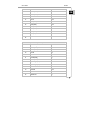
X.21bis/V.36 - 37 poles socket (ISO4902) - DTE mode
PIN CRITERION DIRECTION
23 C114B In
5 C114A In
22 C103B (TxB1) Out
4 C103A (TxA1) Out
26 C115B In

Quick Guide VX2000
19
GB
8 C115A In
24 C104B (RxB1) In
6 C104A (RxA1) In
35 C113B Out
17 C113A Out
13 C109 (DCD) In
12 C108 (DTR) Out
11 C107 (DSR) In
9 C106 (CTS) In
7 C105 (RTS) Out
10 C141 (LL) Out
20, 25, 30,
37
Ground -
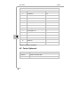
X.21/V.11 - 15 pole socket (ISO4903) - DTE mode
PIN CRITERION DIRECTION
9 C103B (TxB
1
) Out
2 C103A (TxA
1
) Out
13 C115B In
6 C115A In
11 C104B (RxB
1
) In
4 C104A (RxA
1
) In
14 Byte timing A (n.a.) In
7 Byte timing B (n.a.) In
3 Control A Out
10 Control B Out
5 Indication A In
12 Indication B In

Quick Guide VX2000
20
GB
8 Ground -
1
Signals referred to D2000Pro
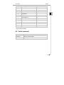
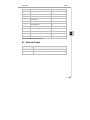
4.2 Optional Codes
CODE DESCRIPTION
6100999171 Cable kit, DTE simulation
6100999172 Cable kit, DCE simulation
La page est en cours de chargement...
La page est en cours de chargement...
La page est en cours de chargement...
La page est en cours de chargement...
La page est en cours de chargement...
La page est en cours de chargement...
La page est en cours de chargement...
La page est en cours de chargement...
La page est en cours de chargement...
La page est en cours de chargement...
La page est en cours de chargement...
La page est en cours de chargement...
La page est en cours de chargement...
La page est en cours de chargement...
La page est en cours de chargement...
La page est en cours de chargement...
La page est en cours de chargement...
La page est en cours de chargement...
La page est en cours de chargement...
La page est en cours de chargement...
La page est en cours de chargement...
La page est en cours de chargement...
La page est en cours de chargement...
La page est en cours de chargement...
La page est en cours de chargement...
La page est en cours de chargement...
La page est en cours de chargement...
La page est en cours de chargement...
La page est en cours de chargement...
La page est en cours de chargement...
La page est en cours de chargement...
La page est en cours de chargement...
La page est en cours de chargement...
La page est en cours de chargement...
La page est en cours de chargement...
La page est en cours de chargement...
La page est en cours de chargement...
La page est en cours de chargement...
La page est en cours de chargement...
La page est en cours de chargement...
La page est en cours de chargement...
La page est en cours de chargement...
La page est en cours de chargement...
La page est en cours de chargement...
La page est en cours de chargement...
La page est en cours de chargement...
La page est en cours de chargement...
La page est en cours de chargement...
La page est en cours de chargement...
La page est en cours de chargement...
La page est en cours de chargement...
La page est en cours de chargement...
La page est en cours de chargement...
La page est en cours de chargement...
La page est en cours de chargement...
La page est en cours de chargement...
La page est en cours de chargement...
La page est en cours de chargement...
La page est en cours de chargement...
La page est en cours de chargement...
La page est en cours de chargement...
La page est en cours de chargement...
La page est en cours de chargement...
La page est en cours de chargement...
La page est en cours de chargement...
La page est en cours de chargement...
La page est en cours de chargement...
La page est en cours de chargement...
-
 1
1
-
 2
2
-
 3
3
-
 4
4
-
 5
5
-
 6
6
-
 7
7
-
 8
8
-
 9
9
-
 10
10
-
 11
11
-
 12
12
-
 13
13
-
 14
14
-
 15
15
-
 16
16
-
 17
17
-
 18
18
-
 19
19
-
 20
20
-
 21
21
-
 22
22
-
 23
23
-
 24
24
-
 25
25
-
 26
26
-
 27
27
-
 28
28
-
 29
29
-
 30
30
-
 31
31
-
 32
32
-
 33
33
-
 34
34
-
 35
35
-
 36
36
-
 37
37
-
 38
38
-
 39
39
-
 40
40
-
 41
41
-
 42
42
-
 43
43
-
 44
44
-
 45
45
-
 46
46
-
 47
47
-
 48
48
-
 49
49
-
 50
50
-
 51
51
-
 52
52
-
 53
53
-
 54
54
-
 55
55
-
 56
56
-
 57
57
-
 58
58
-
 59
59
-
 60
60
-
 61
61
-
 62
62
-
 63
63
-
 64
64
-
 65
65
-
 66
66
-
 67
67
-
 68
68
-
 69
69
-
 70
70
-
 71
71
-
 72
72
-
 73
73
-
 74
74
-
 75
75
-
 76
76
-
 77
77
-
 78
78
-
 79
79
-
 80
80
-
 81
81
-
 82
82
-
 83
83
-
 84
84
-
 85
85
-
 86
86
-
 87
87
-
 88
88


Aethra VX2000 Manuel utilisateur
- Taper
- Manuel utilisateur
- Ce manuel convient également à
dans d''autres langues
- italiano: Aethra VX2000 Manuale utente
- English: Aethra VX2000 User manual
- español: Aethra VX2000 Manual de usuario
- Deutsch: Aethra VX2000 Benutzerhandbuch
Autres documents
-
Linon Kennedy Backless Counter Stool Black Whi Assembly Instructions
-
Patton electronic TV Converter Box IC-V.24 Manuel utilisateur
-
-
RODE Microphones WGOIIRX Mode d'emploi
-
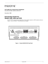 Paradyne ACCULINK 3160 Supplementary Manual
-
Triax 310039 Manuel utilisateur
-
Panasonic CQVX2000U Mode d'emploi
-
AOpen VX2KUG Le manuel du propriétaire
-
Sony LCH-VX2000 Manuel utilisateur
-
Sony LCH-FXA Manuel utilisateur
