
1 de 12
Tyco Electronics France SAS, B.P. 30039 95301 CERGY-PONTOISE Cedex Tél. : 01 34 20 88 88 Fax : 01 34 20 86 00
Ce document géré par Tyco Electronics France est archivé dans la base de donnée Startec.
Une impression ne peut être considérée comme un document contrôlé.
This document, managed by Tyco Electronics France, is archived in the Startec database.
A printout cannot be considered as a controlled document.
Préconisation d’utilisation
CONNECTEURS 31 VOIES MT/SPT
Recommendations for utilization
31-WAY MT/SPT CONNECTORS
411-15599
26 Janvier 06 Rév. D
SOMMAIRE
1. INTRODUCTION
2. RÉFÉRENCE ET DESCRIPTION DES
PRODUITS
2.1. Produits plastiques
2.2. Contacts
3. SPÉCIFICATIONS
3.1. Spécifications produits
3.2. Opération de sertissage des contacts
3.3. Instructions de démontage des contacts
4. RECOMMANDATIONS PARTICULIÈRES DU
PRODUIT
4.1. Câblage du connecteur
4.1.1 Mise en place des contacts
4.1.2 Mise en place des verrous secondaires
4.1.3 Mise en place du faisceau et capot horizontal
4.1.4 Mise en place du faisceau et capot vertical
4.2. Mise en place du connecteur
4.3. Démontage du connecteur
4.4. Démontage du capot
5. RECOMMANDATIONS PARTICULIÈRES DE
DÉMONTAGE
5.1. Contacts
5.2. Joint axial
6. RECOMMANDATIONS GÉNÉRALES
D’UTILISATION DES CONTACTS
7. RECOMMANDATIONS GÉNÉRALES
D’UTILISATION DES CONNECTEURS
8. PRÉCONISATIONS POUR LA VALIDATION
DE L’ÉQUIPEMENT DE CONTROLE
CABLAGE PAR PUSH-TEST
CONTENTS
1. IINTRODUCTION
2. PRODUCT REFERENCES AND DESCRIP-
TION
2.1. Plastic products
2.2. Contacts
3. SPECIFICATIONS
3.1. Product specifications
3.2. Contact crimping operations
3.3. Contact removal instructions
4. SPECIAL RECOMMENDATIONS REGAR-
DING PRODUCT
4.1. Wiring the connector
4.1.1 Fitting the contacts
4.1.2 Fitting the secondary latches
4.1.3 Fitting the cable bundle and horizontal cover
4.1.4 Fitting the cable bundle and vertical cover
4.2. Fitting the connector
4.3. Removing the connector
4.4. Removing the cover
5. SPECIAL RECOMMENDATIONS FOR
REMOVAL
5.1. Contacts
5.2. Axial seal
6. GENERAL RECOMMENDATIONS FOR
UTILIZATION OF CONTACTS
7. GENERAL RECOMMENDATIONS FOR
UTILIZATION OF CONNECTORS
8. INSTRUCTIONS FOR VALIDATION OF
WIRING PUSH-TEST EQUIPMENT

2 de 12 Rév. D
CONNECTEURS 31 VOIES MT/SPT
31-WAY MT/SPT CONNECTORS
411-15599
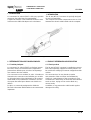
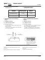
1. INTRODUCTION
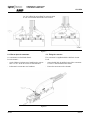
Le connecteur 31 voies MT/SPT a été conçu spéciale-
ment pour être utilisé dans les automobiles.
Compact et robuste, il sert d’élément de liaison entre
le faisceau de câbles électriques et le calculateur.
1. INTRODUCTION
The 31-way MT/SPT connector is specially designed
for use in automobiles.
This compact and robust component serves as a link
between the electric cable bundle and the computer.
Figure 1
2. RÉFÉRENCE ET DESCRIPTION DES PRODUITS
2.1. Produits plastiques
Le connecteur 31 voies MT/SPT est livré pré-assem-
blé. Deux verrous secondaires livrés séparament
peuvent être utilisées pour sécuriser l’encliquetage
des contacts dans leur alvéole.
Il se connecte sur une embase 31 voies. L’insertion et
l’extraction du connecteur sont facilitées par un étrier.
Un joint axial et des joints individuels sur fil assurent
l’étanchéité du raccordement à l’immersion. Un bou-
chon peut être utilisé pour obturer une alvéole non
utilisée.
De plus, un couvercle protègeant les câbles du
faisceau évite toutes détériorations et encrassements
importants.
2. PRODUCT REFERENCES AND DESCRIPTION
2.1. Plastic products
The 31-way MT/SPT connector is supplied pre-assem-
bled. Two separately supplied secondary latches can
be used for the safetying of contacts snapped into their
cavities.
It is connected to a 31-way header. Insertion
and extraction of the connector are facilitated by
a bail lock. Leak-tightness of the connection in case
of immersion is ensured by an axial seal and individual
seals on wires. A plug can be used to blank any
unused cavity.
In addition, a cap protects the cable bundle against
damage and soiling.

CONNECTEURS 31 VOIES MT/SPT
31-WAY MT/SPT CONNECTORS
3 de 12Rév. D
411-15599
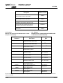
2.2. Contacts
Référence des contacts et joints utilisables dans le connec-
teur (liste non exhaustive)
Désignation
Description
Référence TYCO
Référence TYCO
Couvercle pour connecteur 31 voies, départ à 180°
Cap for 31-way connector, outlet at 180°
953039-x
Couvercle pour connecteur 31 voies, départ à 90°
Cap for 31-way connector, outlet at 90°
953040-x
Connecteur 31 voies assemblé étrier à droite
Assembled 31-way connector, bail lock on right
x-953041-x
Connecteur 31 voies assemblé étrier à gauche
Assembled 31-way connector, bail lock on left
x-953042-x
Verrou MT/SPT
MT/SPT latch
953047-x
953048-x
Référence
Reference
Désignation
Description
Fil
Wire
968035 Clip Standard Power Timer
Receptacle, Standard Power Timer
1 - 2 mm
2
968037 Clip Standard Power Timer
Receptacle, Standard Power Timer
3 - 4 mm
2
962875 Clip Micro Timer 2
Receptacle, Micro Timer 2
0,2 - 0,5 mm
2
962876 Clip Micro Timer 2
Receptacle, Micro Timer 2
0,5 - 1 mm
2
963244 Joint individuel SPT
Individual seal SPT
ø 2,2 - 3,0 mm
2,2 - 3,0 mm dia.
7703397841 Joint individuel SPT
Individual seal SPT
ø 3,1 - 3,4 mm
3.1 - 3.4 mm dia.
963245 Joint individuel SPT
Joint individuel SPT
ø 3,4 - 3,7 mm
3.4 - 3.7 mm dia.
963530-1 Joint individuel Micro Timer
Individual seal, Micro Timer
ø 1,2 - 2,15 mm
1.2 - 2.15 dia. mm
963531-1 Bouchon d’alvéole Micro Timer
Cavity plug, Micro Timer
1394132-1 Bouchon d’alvéole Micro Timer
Cavity plug, Micro Timer
Réf. alternative
Alternative ref.
100132 Bouchon d’alvéole SPT
Cavity plug SPT
172749-2 Bouchon d’alvéole SPT
Cavity plug SPT
Réf. alternative
Alternative ref.
2.2. Contacts
References for contacts and seals usable in the
connector (non-exhaustive list).
Pour le montage des bouchons, se référer à la spécifi-
cation 114-15075.
For the fitting of plugs, see specification 114-15075.

4 de 12 Rév. D
CONNECTEURS 31 VOIES MT/SPT
31-WAY MT/SPT CONNECTORS
411-15599
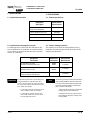
3. SPECIFICATIONS
3.1. Product specifications
3.2. Contact crimping operations
The crimping of contacts must be performed using,
preferably, the following procedures described in the
crimping specifications:
The following special precautions must be taken
when crimping the MT contact with 1 mm
2
wire
in order to avoid having to apply very high inser-
tion forces and being unable to visually detect
when a contact is not latched.
• There must not be any bead in front of the
crimping wings on the crimped joint.
• Crimping must not be too right in order to
avoid damaging the joint or causing exces-
sive elongation
NOTE
3. SPECIFICATIONS
3.1. Spécifications produits
3.2. Opérations de sertissage des contacts
Le sertissage des contacts doit être effectué en utili-
sant de préférence les outillages de sertissage AMP
et en suivant les procédures données par les spécifi-
cations de sertissage :
Des précautions particulières doivent être prises
pour le sertissage du contact MT avec du fil
1 mm
2
sous peine d’avoir des efforts d’insertion
très élevés et un risque de non détection visuelle
d’un contact non verrouillé.
• le joint serti ne doit pas présenter de bour-
relet à l’avant des ailes de sertissage
• le sertissage ne doit pas être trop serré
pour ne pas détériorer le joint et pour évi-
ter un allongement excessif.
Désignation
Description
Spécifications
Specifications
Connecteur 31voies MT/SPT
31-way connector MT/SPT
108-15172
Contact, Standard Power Timer 108-18037
Contact, Micro Timer 2 108-18055
Interface 208-15558
Désignation
Description
Références
References
Spécifications
Specifications
Clip Standard Power Timer
Receptacle, Standard Power Timer
968035
968037
114-18037
Clip Micro Timer 2
Receptacle, Micro Timer 2
962875
962876
114-18081
Systèmes d’étanchéité par joint individuel
Sealing system with individual seal
963530
114-18018
REMARQUE

CONNECTEURS 31 VOIES MT/SPT
31-WAY MT/SPT CONNECTORS
5 de 12Rév. D
411-15599
3.3. Instructions de démontage des contacts
(voir annexe 1 et 2)
4. RECOMMANDATIONS PARTICULIÈRES DU
PRODUIT
4.1. Cablâge du connecteur
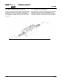
4.1.1. Mise en place des contacts
Le connecteur comprend :
- 27 alvéoles pour clip Micro Timer 2 (dont 2 pour
clips à cage doré).
- 4 alvéoles pour clip Standard Power Timer (dont
1 pour clip à cage doré).
Câbler les voies comme préconisé dans la notice
411-15515.
Mettre des bouchons pour les voies non utilisées
Désignation
Description
Notices techniques
Technical manuals
Références
References
Outil d’extraction clip SPT
SPT receptacle extraction tool
411-15057 1-1579007-6
Outil d’extraction clip MT2
MT2 receptacle extraction tool
411-15058 539960-1
Figure 2
Alvéoles pour clips à cage doré
MT2 RECEPTACLE
SPT RECEPTACLE
3.3. Contact removal instructions
(see Appendices 1 and 2)
4. SPECIAL RECOMMENDATIONS REGARDING
PRODUCT
4.1. Wiring the connector
4.1.1. Fitting the contacts
The connector comprises:
- 27 cavities for Micro Timer 2 receptacle (including
two for gold-plated cage receptacles),
- 4 cavities for Standard Power Timer receptacle
(including one for gold-plated cage receptacles).
Wire the positions as described in manual
411-15515.
Fit plugs for unused positions.
Cavities for gold-plated cage
receptacles

6 de 12 Rév. D
CONNECTEURS 31 VOIES MT/SPT
31-WAY MT/SPT CONNECTORS
411-15599
4.1.2. Mise en place des verrous secondaires
Insérer les verrous dans leurs glissières respectives et
les enfoncer à fond (ils ne doivent pas dépasser du
boîtier intérieur). Si la manoeuvre s’avère difficile (F >
50 N), parfaire l’insertion des contacts et renouveler
l’opération.
Figure 3
4.1.2. Fitting the secondary latches
Insert the latches in their respective keyways and push
them fully home (They must not protrude from the
inner housing). If this cannot be done easily (F > 50 N),
insert the contacts properly and repeat this operation.

CONNECTEURS 31 VOIES MT/SPT
31-WAY MT/SPT CONNECTORS
7 de 12Rév. D
411-15599
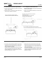
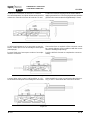
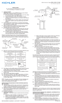
4.1.3. Mise en place du faisceau et capot horizontal
→ Former le toron de câble vers la droite ou la gauche
selon la sortie choisie.
→ Mettre en place le capot (livré à part) comme indi-
qué dans les schémas ci-dessous :
→ Une fois le capot verrouillé, installer le toron dans
la goulotte du capot et positionner un collier serre-
câbles de largeur comprise entre 3,6 et 4,8 mm
dans la gorge de la goulotte.
L’attache du serre-câble doit se trouver sur l’un des
côtés de la goulotte (voir dessin) pour obtenir un
serrage optimal avec un encombrement minimum
(efort de serrage maxi : 220 N).
Figure 4
puis glisser celui-ci vers la droite ou la gauche
selon la sortie choisie.
Un "clic" indique le verrouillage du capot sur le boîtier.
Placer le capot dans les rampes du boîtier
puis glisser celui-ci vers la droite ou la gauche
selon la sortie choisie.
Position the cover in the guides on the housing
A "click" sound indicates that the cover is latched on the housing.
Un "clic" indique le verrouillage du capot sur le boîtier.
4.1.3. Fitting the loop and horizontal cover
→
Route the cable strand to the right or left, depending
on the selected outlet.
→
Fit the cover (supplied separately) as shown in the
diagrams below:
→
When the cover has been latched, fit the cable
strand in the channel in the cover and position a
cable clamp between 3.6 and 4.8 mm wide in the
recess on the channel.
The cable clamp fastener must be located to one
side of the channel (see drawing) in order to obtain
optimal clamping with minimum size (max. clam-
ping force: 220 N).
Then slide the housing to the right of left,
depending on the selected outlet.
Puis glisser celui-ci vers la droite ou la gauche
selon la sortie choisie.

8 de 12 Rév. D
CONNECTEURS 31 VOIES MT/SPT
31-WAY MT/SPT CONNECTORS
411-15599
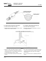
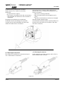
4.1.4. Mise en place du faisceau et capot vertical
→ Former le toron de câble vers le haut.
→ Mettre en place un demi capot (livré à part) comme
indiqué sur les schémas suivants :
→ Mettre un collier serre-câble de largeur comprise
entre 3,6 et 4,8 mm dans la gorge de la goulotte. Le
présenter de façon à ce que l’attache se trouve sur
le côté (effort maxi de serrage : 220 N).
→ Mettre le second demi capot pour finir de protéger
le toron.
Figure 5
COLLIER DE SERRE-CABLE
CABLE CLAMP FASTENER
Figure 6
Un "clic" indique le verrouillage du capot sur le boîtier.
A "click" sound indicates that the cover is latched on the housing.
4.1.4. Fitting the cable bundle and vertical cover
→
Route the cable strand upwards.
→
Fit a half cover (supplied separately) as shown in
the diagrams below
→
Fit a cable clamp grip between 3.6 and 4.8 mm wide
in the recess on the channel. Position it so that the
fastener is located on the side (max. clamping
force: 220 N).
→
Fit the second half cover to completely protect the
strand.
ATTACHE DU COLLIER
CABLE CLAMP GRIP
COLLIER DE SERRE-CABLE
CABLE CLAMP FASTENER

CONNECTEURS 31 VOIES MT/SPT
31-WAY MT/SPT CONNECTORS
9 de 12Rév. D
411-15599
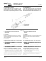
4.2. Mise en place du connecteur
Le connecteur est livré étrier fermé.
Pour le monter :
- Ouvrir l’étrier en le tirant vers l’extérieur du connec-
teur. Un "clic" de fin de course se fait entendre
- Présenter le connecteur sur l’embase.
Figure 7
Un "clic indique le verrouillage du second capot
Un "clic indique le verrouillage du second capot
A "click" sound indicates that the half cover is latched.
Figure 8
4.2. Fitting the connector
The connector is supplied with the bail lock closed.
To fit:
- Open the bail lock by pulling it out of the connector.
A "click" is heard at the end of travel.
- Place the connector on the header.

10 de 12 Rév. D
CONNECTEURS 31 VOIES MT/SPT
31-WAY MT/SPT CONNECTORS
411-15599
Positionner le connecteur et l’enficher sur l’embase
sans effort important, les 6 plots doivent rentrer dans les
rainures du connecteur (course de l’ordre de 7,5 mm).
Si l’effort est important ou si le connecteur se met de
travers, vérifier que le sens de montage a été respecté
(détrompage).
Pousser l’étrier vers l’avant pour continuer l’accouple-
ment du connecteur.
Lorsque l’étrier arrive contre le côté du boîtier, un "clic"
se fait entendre indiquant le verrouillage du connecteur.
Figure 9
Figure 10
Figure 11
Position the connector and plug it into the header without
applying excessive force. The six keying studs must enter the
grooves in the connector (travel of approximately 7.5 mm).
If excessive force us required or if the connector cannot
be correctly aligned, check compliance with the correct
direction of fitting (foolproofing).
Push the bail lock forwards to complete the connector
mating.
When the bail lock comes up against the side of the hou-
sing, a "click" is heard when the connector is latched.

CONNECTEURS 31 VOIES MT/SPT
31-WAY MT/SPT CONNECTORS
11 de 12Rév. D
411-15599
Si l’effort est trop important tirer en arrière
l’étrier jusqu’au "clic", retirer le connecteur,
vérifier que :
●
le joint est bien en place,
●
les verrous secondaires et les clips sont en place,
●
les languettes de l’embase ne sont ni tordues ni
détériorées.
Recommencer l’opération d’accouplement.
Vérification du bon verrouillage du connecteur :
s’assurer que les deux extrémités de l’étrier sont
visibles de l’autre côté du connecteur.
4.3. Démontage du connecteur
Tirer l’étrier vers l’extérieur du connecteur jusqu’au
"clic". Désengager le connecteur.
Figure 12
Figure 13
If excessive force is require, pull the bail lock bac-
kwards until a "click" is heard, then withdraw the con-
nector. Check that:
●
the seal is correctly positioned;
●
the secondary latches and receptacles are in
place;
●
the tabs on the header are not bent or damaged.
Start the mating operation again.
Check that the connector latches correctly: Make sure
the two ends of the bail lock are visible on the other
side of the connector.
4.3. Removing the connector
Pull the bail lock out of the connector until a "click" is
heard. Withdraw the connector.

12 de 12 Rév. D
CONNECTEURS 31 VOIES MT/SPT
31-WAY MT/SPT CONNECTORS
411-15599
4.4. Démontage du couvercle
Couper le collier serre-câble puis à l’aide d’un objet
pointu, appuyer sur les clips de rétention du capot,
puis procéder à l’inverse du point 4.1.3 pour les capots
horizontaux et 4.1.4 pour les capots verticaux.
5. RECOMMANDATIONS PARTICULIERES DE
DEMONTAGE
5.1. Contacts
Enlever le couvercle du connecteur puis procéder
comme préconisé dans la notice technique décrite
dans le paragraphe 3.
5.2. Joint axial
Le joint ne doit pas être démonté. S’il est défectueux,
remplacer le connecteur.
6. RECOMMANDATIONS GENERALES D’UTILISATION
DES CONTACTS
Manuel de recommandations générales 411-15516.
7. RECOMMANDATIONS GENERALES D’UTILISATION
DES CONNECTEURS
Manuel de recommandations générales 411-15515.
8. PRECONISATIONS POUR LA VALIDATION DE L’EQUI-
PEMENT DE CONTROLE CABLAGE PAR "PUSH TEST"
Se référer au manuel de recommandations générales
411-15517 ainsi qu’au plan de préconisation d’équipe-
ment de contrôle-cablâge par push-test, 411-15600.
Figure 14
CLIP DE RETENTION
RETAINING CATCH
4.4. Removing the cap
Cut the cable clamp grip and then use a pointed imple-
ment to press the cover retaining catches. Then carry
out, in reverse order, the steps in paragraph 4.1.3 for
horizontal covers and 4.1.4 for vertical covers.
5. SPECIAL RECOMMENDATIONS FOR
REMOVAL
5.1. Contacts
Remove the cap from the connector and then proceed
as described in the technical manual specified in
section 3.
5.2. Axial seal
This seal must not be removed. If it is faulty, replace
the connector.
6. GENERAL RECOMMENDATIONS FOR UTILIZATION
OF CONTACTS
General recommendations manual 411-15516.
7. GENERAL RECOMMENDATIONS FOR UTILIZATION
OF CONNECTORS.
General recommendations manual 411-15515.
8. INSTRUCTIONS FOR VALIDATION OF WIRING
PUSH-TEST EQUIPMENT
See general recommendations manual 411-15517 and
the guide drawing for wiring push-test equipment,
411-15600.
-
 1
1
-
 2
2
-
 3
3
-
 4
4
-
 5
5
-
 6
6
-
 7
7
-
 8
8
-
 9
9
-
 10
10
-
 11
11
-
 12
12


Tyco Electronics 953040-1 Manuel utilisateur
- Taper
- Manuel utilisateur
- Ce manuel convient également à
dans d''autres langues
Autres documents
-
Toro Cable Connector Guide d'installation
-
Westinghouse One-Light Outdoor Wall Lantern 6692400 Manuel utilisateur
-
-
 Kichler Lighting 49686BKL18 Manuel utilisateur
-
-
