Terex Genie GR06-7389 Installation Instructions Manual
- Taper
- Installation Instructions Manual

Rev 2
FAILURE TO COMPLETE THIS BULLETIN MAY
RESULT IN DEATH OR SERIOUS INJURY.
1 of 5
CAMPAIGN BULLETIN 090007
Original Release Date: October 29, 2009
Revised Date: 25-01-2010
Subject: Platforms with Gated Entry
Models and Serial Numbers Affected:
GR : GR-101 to GR09-14664
AWP: 3896-101 to 3801-21190
AWP02-21198 to AWP09-65432
IWP : 4096-101 to 4001-4199
IWP02-4218 to IWP09-8283
CWP : 0001-109
0196-118 to 0101-1248
CWP02-1249
SP : 1796-101 to 1797-255
Allowable Hours: 30 minutes
Issue:
Genie Industries, Inc. has received reports that the gate in the above referenced machines can
fail to latch. If the gate does not latch, the guard rail system does not provide the required
level of fall protection for the operator.

Rev 2
FAILURE TO COMPLETE THIS BULLETIN MAY
RESULT IN DEATH OR SERIOUS INJURY.
2 of 5
CAMPAIGN BULLETIN 090007
Action Required:
1. Immediately locate all machines within the serial number ranges shown above.
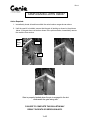
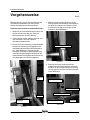
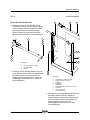
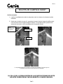
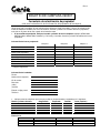
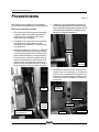
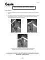
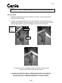
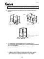
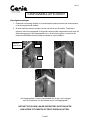
2. Until the new kit is installed, ensure that the gate is latching as shown in the pictures
below. If the gate does not latch as shown in the pictures below, immediately remove
the machine from service.
Gate is properly latched when the pin is engaged in the slot
underneath the gate swing arm
slot
p
in
gate
swing
arm

Rev 2
FAILURE TO COMPLETE THIS BULLETIN MAY
RESULT IN DEATH OR SERIOUS INJURY.
3 of 5
CAMPAIGN BULLETIN 090007
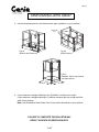
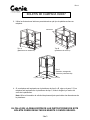
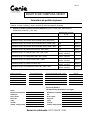
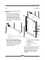
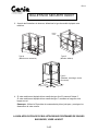
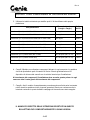
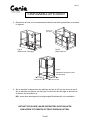
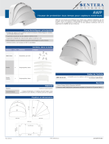
floor length floor width
double side
entry
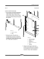
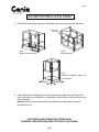
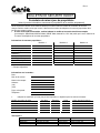
3. Use the illustrations below, and determine the type of platform on your machine.
Type A Type B
(Platform with Extension) (Utility Platform)
Type C
(Standard, Extra Large, Narrow
and Ultra Narrow)
4. If your machine is equipped with type A or B platform, continue on to step 5.
If your machine is equipped with type C platform, measure the floor length and floor
width of the platform.
Note: Use the attached Parts Order Form to record the dimensions of your platform.

Rev 2
FAILURE TO COMPLETE THIS BULLETIN MAY
RESULT IN DEATH OR SERIOUS INJURY.
4 of 5
CAMPAIGN BULLETIN 090007
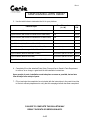
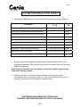
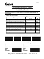
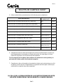
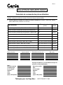
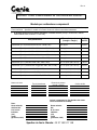
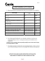
5. Use the table below to determine the kit for your platform:
Platform Style
Floor Dimension
(L x W)
Kit
P/N
Type A Platform (GR models from GR-101 to GR01-341) N/A 145325
Type A Platform (GR models from GR01-342 to GR05-5000) N/A 145187
Type A Platform (GR models from GR05-5001 to GR06-7389) N/A 145321
Type A Platform (GR models from GR06-7390 to GR09-14664) N/A 145186
Type B Platform (Utility Platform: SP or CWP) N/A 145277
Type C Platform (Standard : AWP, IWP , CWP or GR) 26 in x 27 in (66 cm x 68 cm) 145183
Type C Platform (Extra Large : AWP, IWP or CWP) 30 in x 27 in (76 cm x 68 cm) 145183
Type C Platform (Narrow: AWP,IWP or CWP) 26 in x 20 in (66 cm x 51 cm) 145184
Type C Platform (Narrow: GR model) 26 in x 20 in (66 cm x 51 cm) 145270
Type C Platform (Ultra Narrow: AWP,IWP, CWP or GR) 22 in x 18 in (56 cm x 48 cm) 145185
6. Completely fill out the attached Parts Order Form and fax to Genie’s Parts Department
to receive, at no charge, a gate latch kit with installation instructions.
Upon receipt of parts, installation must take place as soon as possible, but no later
than 30 days from receipt of parts.
7. Fill out and sign the completion form included with the instructions in the parts kit and fax
to Genie’s warranty department to verify that this campaign bulletin has been completed.

Rev 2
FAILURE TO COMPLETE THIS BULLETIN MAY
RESULT IN DEATH OR SERIOUS INJURY.
5 of 5
CAMPAIGN BULLETIN 090007
Warranty:
The labor and travel distance required to perform this inspection and installation are covered
under the provisions of our warranty agreement. Warranty claims can be submitted by paper
claim or online. Please combine as many machines as possible on one claim form. If you need
more information about filing a warranty claim, call Genie’s warranty department.
If you are the owner of an affected machine and are not an authorized Genie dealer,
please contact your nearest Genie dealer for assistance in completing this bulletin. Only
Genie Authorized Dealers will be reimbursed for labor or any other costs associated with
this bulletin under the provisions of our standard warranty terms and conditions.
Local norms and regulations requires that the seller of a Genie machine report to Genie the
model and serial number of each machine sold, as well as the name, address, and telephone
number of the new owner, within 60 days of the sale.
Regulations also require that the manufacturer’s campaign bulletins be completed. It is your
responsibility to communicate this important information to all machine owners and applicable
branches. If you require additional copies of this bulletin or have any questions, please contact
Genie’s service department at:
UK: 00 44 1476 584 333
France: 00 33 237 260 986
Germany: 00 49 422 1491821
Italy: 0039 075 941 8171
Iberica: 0034 935 725 380
Scandinavia: 0046 3157 5154
Middle East: 0097 143 391 800 or
0097 150 459 7937
All other locations: 0031 653 221 908
Enclosures:
Parts order form
Owner update form
Machine list report

Rev 2
CAMPAIGN BULLETIN 090007
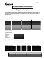
Owner Update Form
(for updating machine owner information only)
Genie requires that the seller of a Genie machine report to Genie the model and serial number of each
machine sold, as well as the name, address, and telephone number of the new owner, within 60 days of the
sale.
• If you have sold a machine, list the complete model and serial number (example: GR05-5062, AWP06-
52934, IWP08-7698, 0198-627 and 1797-183)
and the name, address and phone number of the new owner.
New Owner Information:
Machine 1
Machine 2
Machine 3
Model*
Serial Number*
Owner Name*
Address 1*
Address 2
City/State/Zip*
Phone Number*
Contact Person
* Required fields.
Seller Information:
Date:
Company Name:
Account #:
Address:
(street)
(city)
State, zip code
Phone #:
• List any machines that could not be inspected or repaired because of the following:
Model & Serial Number Scrapped Exported Stolen Others (explain)
- - - -
- - - -
- - - -
- - - -
Fax to:
UK: 0044 1476 584 330 Italy : 0039 075 941 8146
France: 0033 237 310 300 Scandinavia: 0046 3157 5104
Germany: 0049 422 149 1820 Middle East: 0097 143 391 802
Iberica: 0034 935 725 080 All other locations: 0031 183 581 566

Rev 2
CAMPAIGN BULLETIN 090007
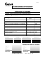
Parts Order Form
Fax this form to Genie Industries to receive the indicated Gate Latch Kit for your machine. List the model and
serial number of each affected machine.
• Please list the complete model and serial number (example: GR05-5062, AWP06-52934,
IWP08-7698, 0198-627 and 1797-183)
Platform Style
Floor Dimension
(L x W)
Kit P/N
Type A Platform (GR models from GR-101 to GR01-341) N/A 145325
Type A Platform (GR models from GR01-342 to GR05-5000) N/A 145187
Type A Platform (GR models from GR05-5001 to GR06-7389) N/A 145321
Type A Platform (GR models from GR06-7390 to GR09-14664) N/A 145186
Type B Platform (Utility Platform: SP or CWP) N/A 145277
Type C Platform (Standard : AWP, IWP , CWP or GR) 26 in x 27 in (66 cm x 68 cm) 145183
Type C Platform (Extra Large : AWP, IWP or CWP) 30 in x 27 in (76 cm x 68 cm) 145183
Type C Platform (Narrow: AWP,IWP or CWP) 26 in x 20 in (66 cm x 51 cm) 145184
Type C Platform (Narrow: GR model) 26 in x 20 in (66 cm x 51 cm) 145270
Type C Platform (Ultra Narrow: AWP,IWP, CWP or GR) 22 in x 18 in (56 cm x 48 cm) 145185
Serial Number Platform Type Floor Dimension (L x W) Kit P/N
- - -
- - -
- - -
- - -
- - -
Send Parts to: (If you would like to send
parts to a different location)
Date:
Company Name Company Name:
Ordered By: Attn:
Account No.: Account No.:
Address: Address:
(street) (street)
(city) (city)
(state, zip code) (state, zip code)
Fax to Holland: 00 31 165 511 148

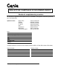
Parts Manual
Serial Number Range
Installation Instructions
Part No. 145159
Rev B
Gated Entry
AWP
IWP
GR
CWP
SP

REV B
2 AWP • IWP • CWP • SP • GR Part No. 145159
Installation Instructions
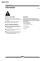
Information
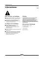
Observe and Obey:
Repair procedures shall be completed by a
person trained and qualified on the repair of this
machine.
Immediately tag and remove from service a
damaged or malfunctioning machine.
Before Starting Installation:
Read, understand and obey the safety rules
and operating instructions in the appropriate
Operator's Manual.
Be sure that all necessary tools and parts are
available and ready for use.
Read this procedure completely and adhere to
the instructions. Attempting shortcuts may
produce hazardous conditions.
Important:
This procedure is for the replacement of the
gated entry mid-rail on certain AWP, IWP, CWP,
SP and GR machines, as required by Campaign
Bulletin 090007.
Tools required:
7
/16 inch combination wrench
7
/16 inch socket
3
/8 inch drive ratchet
Screwdriver
Gated Entry

REV B
Installation Instructions
Part No. 145159 AWP • IWP • CWP • SP • GR 3
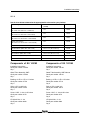
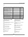
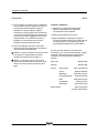
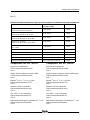
Use the chart below to determine the appropriate kit to be used on your platform.
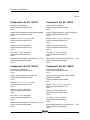
Components of Kit 145183
Installation Instructions
Genie part number 145159
Qty. 1
Gated Tube Assembly, AWP
Genie part number 145190
Qty. 1
Bushing,
3
/8 OD x
1
/4 ID x 1.5 inches
Genie part number 37719
Qty. 2
Shim, 0.375 x 0.063 inch
Genie part number 12013
Qty. 4
Screw - HHC,
1
/4 -20 x 2.25 inches
Genie part number 8179
Qty. 2
LP Nylock Nut,
1
/4 -20
Genie part number 6889
Qty. 2
Components of Kit 145184
Installation Instructions
Genie part number 145159
Qty. 1
Gated Tube Assembly, AWP Narrow
Genie part number 145191
Qty. 1
Bushing,
3
/8 OD x
1
/4 ID x 1.5 inches
Genie part number 37719
Qty. 2
Shim, 0.375 x 0.063 inch
Genie part number 12013
Qty. 4
Screw - HHC,
1
/4 -20 x 2.25 inches
Genie part number 8179
Qty. 2
LP Nylock Nut,
1
/4 -20
Genie part number 6889
Qty. 2
Platform Style Floor Dimension Kit P/N
(L x W)
Platform with extension
(GR models from GR01-101 to GR01-341)
N/A 145325
Platform with extension
(GR models from GR01-342 to GR 05-5000)
N/A 145187
Platform with extension, LH
(GR models from GR 05-5001 to GR 06-7389)
N/A 145321
Platform with extension
(GR models from GR 06-7390 to GR 09-14664)
N/A 145186
Utility Platform (Stock Picker or CWP) N/A 145277
Standard Platform (AWP, IWP, CWP or GR) 26 in x 27 in (66 cm x68 cm) 145183
Extra Large Platform (AWP, IWP or CWP) 30 in x 27 in (76 cm x68 cm) 145183
Narrow Platform (AWP, IWP or CWP) 26 in x 20 in (66 cm x 51 cm) 145184
Narrow Platform (GR model) 26 in x 20 in (66 cm x 51 cm) 145270
Ultra Narrow Platform (AWP, IWP or CWP) 22 in x 18 in (56 cm x48 cm) 145185

REV B
4 AWP • IWP • CWP • SP • GR Part No. 145159
Installation Instructions
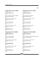
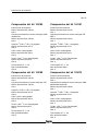
Components of Kit 145185
Installation Instructions
Genie part number 145159
Qty. 1
Gated Tube Assembly, AWP Ultra Narrow
Genie part number 145192
Qty. 1
Bushing,
3
/8 OD x
1
/4 ID x 1.5 inches
Genie part number 37719
Qty. 2
Shim, 0.375 x 0.063 inch
Genie part number 12013
Qty. 4
Screw - HHC,
1
/4 -20 x 2.25 inches
Genie part number 8179
Qty. 2
LP Nylock Nut,
1
/4 -20
Genie part number 6889
Qty. 2
Components of Kit 145186
Installation Instructions
Genie part number 145159
Qty. 1
Gated Tube Assembly, GR
Genie part number 145193
Qty. 1
Bushing,
3
/8 OD x
1
/4 ID x 1.5 inches
Genie part number 37719
Qty. 2
Shim, 0.375 x 0.063 inch
Genie part number 12013
Qty. 4
Screw - HHC,
1
/4 -20 x 2.25 inches
Genie part number 8179
Qty. 2
LP Nylock Nut,
1
/4 -20
Genie part number 6889
Qty. 2
Components of Kit 145187
Installation Instructions
Genie part number 145159
Qty. 1
Gated Tube Assembly, GR GEN 1
Genie part number 145194
Qty. 1
Bushing,
3
/8 OD x
1
/4 ID x 1.5 inches
Genie part number 37719
Qty. 2
Shim, 0.375 x 0.063 inch
Genie part number 12013
Qty. 4
Screw - HHC,
1
/4 -20 x 2.25 inches
Genie part number 8179
Qty. 2
LP Nylock Nut,
1
/4 -20
Genie part number 6889
Qty. 2
Components of Kit 145270
Installation Instructions
Genie part number 145159
Qty. 1
Gated Tube Assembly, AWP Narrow Platform GR
Genie part number 145269
Qty. 1
Bushing,
3
/8 OD x
1
/4 ID x 1.5 inches
Genie part number 37719
Qty. 2
Shim, 0.375 x 0.063 inch
Genie part number 12013
Qty. 4
Screw - HHC,
1
/4 -20 x 2.25 inches
Genie part number 8179
Qty. 2
LP Nylock Nut,
1
/4 -20
Genie part number 6889
Qty. 2

REV B
Installation Instructions
Part No. 145159 AWP • IWP • CWP • SP • GR 5
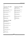
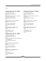
Components of Kit 145277
Installation Instructions
Genie part number 145159
Qty. 1
Gated Tube Assembly, CWP Utility Platform
Genie part number 145278
Qty. 1
Bushing,
3
/8 OD x
1
/4 ID x 1.5 inches
Genie part number 37719
Qty. 2
Shim, 0.375 x 0.063 inch
Genie part number 12013
Qty. 4
Screw - HHC,
1
/4 -20 x 2.25 inches
Genie part number 8179
Qty. 2
LP Nylock Nut,
1
/4 -20
Genie part number 6889
Qty. 2
Components of Kit 145321
Installation Instructions
Genie part number 145159
Qty. 1
Gated Tube Assembly, GR Gated LH
Genie part number 145320
Qty. 1
Bushing,
3
/8 OD x
1
/4 ID x 1.5 inches
Genie part number 37719
Qty. 2
Shim, 0.375 x 0.063 inch
Genie part number 12013
Qty. 4
Screw - HHC,
1
/4 -20 x 2.25 inches
Genie part number 8179
Qty. 2
LP Nylock Nut,
1
/4 -20
Genie part number 6889
Qty. 2
Components of Kit 145325
Installation Instructions
Genie part number 145159
Qty. 1
Gated Tube Assembly, GR GEN 1 LG
Genie part number 145326
Qty. 1
Bushing,
3
/8 OD x
1
/4 ID x 1.5 inches
Genie part number 37719
Qty. 2
Shim, 0.375 x 0.063 inch
Genie part number 12013
Qty. 4
Screw - HHC,
1
/4 -20 x 2.25 inches
Genie part number 8179
Qty. 2
LP Nylock Nut,
1
/4 -20
Genie part number 6889
Qty. 2

REV B
6 AWP • IWP • CWP • SP • GR Part No. 145159
Installation Instructions
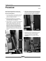
Note: Perform this procedure on a firm, level
surface with the platform in the stowed position.
Remove Existing Mid Rail
1 Turn the key switch to the off position and push
in the red Emergency Stop button to the off
position at the ground controls.
2 Working at the gated entry of the platform,
locate the gas strut connected to the mid-rail
and vertical channel of the platform.
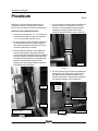
3 Using Illustration 1 as a guide and working at the
extension side of the gas strut, insert a flat
blade screwdriver between the indent of the
plastic ball socket and retaining clip. At the
same time, carefully move the retaining clip
away from the socket and remove the lower
half of the gas strut from the ball stud. Do not
remove the retaining clip from the plastic ball
socket.
Procedure
4 Working at the gated entry mid rail opposite the
entry knob, remove the fasteners securing the
mid-rail to the vertical channel of the platform.
Discard the fasteners. Refer to Illustration 2.
Gas Strut
Plastic Ball Socket
and Retaing Clip
Ball Stud
Illustration 1
Illustration 2
5 Working at the side of the gated entry mid-rail
with the entry knob, remove the fasteners
securing the mid-rail to the hinge plates.
Discard the mid-rail and fasteners. Refer to
Illustration 3.
Mid-Rail
Fasteners
Illustration 3
Entry Knob
Mid-Rail
Fasteners
Hinge Plates
Gas Strut
Ball Strut
Plastic Ball Socket
and Retaining Clip
Fasteners
Mid-Rail
Fasteners
Entry Knob
Hinge Plates
Fasteners
Mid-Rail
Fasteners
Fasteners

REV B
Installation Instructions
Part No. 145159 AWP • IWP • CWP • SP • GR 7
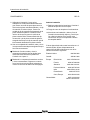
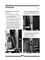
PROCEDURE
Install the Gated Tube Assembly
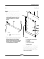
6 Using Illustration 4 as a guide and working with
the provided gated tube assembly (Genie part
number 145190, 145191, 145192, 145193,
145194, 145269, 145278, 145320 or 145326),
install the provided bushings and shims (Genie
part numbers 37719 and 12013) onto the gated
tube assembly.
Illustration 4
a gated tube assembly
b shim
c bushing
7 Working at the side of the gated entry
assembly with the entry knob and using the
provided fasteners (Genie part numbers 8179
and 6889), install the gated tube assembly onto
the hinge plates. Torque the fasteners to 100 in-
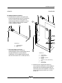
lbs / 11.3 Nm. Refer to Illustration 5.
Illustration 5
a gated entry assembly
b gated tube assembly
c ball stud
d plastic ball socket
e retaining clip
f platform rail vertical channel
g screw
h nylock nut
i hinge plate
8 Using the provided fasteners (Genie part
numbers 8179 and 6889), install the opposite
end of the gated tube assembly to the platform
rail vertical channel. Torque the fasteners to
100 in-lbs / 11.3 Nm. Refer to Illustration 5.
a b
c
b
b
c
b
ba
gh
i
c
g
h
de
f

REV B
8 AWP • IWP • CWP • SP • GR Part No. 145159
Installation Instructions
PROCEDURE
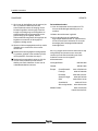
9 Using Illustration 5 as a guide and working at the
extension side of the gas strut, insert a flat
blade screwdriver between the indent of the
plastic ball socket and retaining clip. At the
same time, carefully move the retaining clip
away from the socket and install the lower half
of the gas strut onto the ball stud. Remove the
screwdriver from the retaining clip and plastic
ball socket, making sure the retaining clip fully
seats around the ball socket.
10 After the installation is complete, open and
close the entry gate to ensure it is working
properly.
Result: When the entry gate is opened and
closed, the gate slides inside the vertical
channel of the platform. Proceed to step 11.
Result: The entry gate is not opening and
closing properly. Contact the Genie Industries
Service Department at one of the telephone
numbers on this page.
Finish the Installation
11 Perform function tests. Refer to the operator's
manual on your machine.
12 Return the machine to service.
13 Upon completion of this installation, fill out and
sign the attached Completion Form and fax to
Genie Industries. This will serve as verification
that you have completed Campaign Bulletin
090007.
If you have any further questions regarding these
instructions or need assistance, please contact the
Genie Industries Service Department at one of the
following telephone numbers:
United States: 800-536-1800
Canada: 425-881-1800
Europe: UK 0044 1476 584 333
France 0033 237 260 986
Germany 0049 422 149 1821
Iberica 0034 935 725 380
Scandinavia 0046 3157 5154
other locations 0031 653 221 908
Middle East: 0097 143 391 800
or 0097 150 459 7937
Italiy 0039 075 941 8146

CAMPAIGN BULLETIN 090007
Completion Form
Your signature on this form will verify that you have installed the Gated Entry Kit specified for your
machine.
Fax to: UK 0044 1476 584 330
France 0033 237 310 300
Germany 0049 422 149 1820
Iberica 0034 935 725 080
Italy 0039 075 941 8146
Scandinavia 0046 3157 5104
Middle East 0097 143 391 802
All other locations 0031 183 581 566
Date:
Company Name:
Account # (if applicable)
Address:
(street)
(city)
(state, zip code)
Phone
Please list the complete serial number (example: AWP04- 27766, IWP04-5186 or GR04-4009)
Serial Number:
Serial Number:
Signature (service manager)

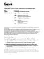
CAMPAIGN BULLETIN 090007 Supplement
Date: 25-01-2010
Subject: Platforms with Gated Entry
Model and Serial Numbers Affected:
GR : GR-101 to GR09-14664
AWP: 3896-101 to 3801-21190
AWP02-21198 to AWP09-65432
IWP: 4096-101 to 4001-4199
IWP02-4218 to IWP09-8283
CWP: 0001-109
0196-118 to 0101-1248
CWP02-1249
SP : 1796-101 to 1797-255
This letter is a supplement to Campaign Bulletin 090007 released on October 29, 2009.
The serial number range of affected machines has not changed. However, the kit list has
been updated. Two more kits were added for GR models equipped with gated extension
platform (type A platform). The machines affected are units from serial number GR-101 to
GR01-341 and from GR05-5001 to GR06-7389. Enclosed is an updated version of the
bulletin and the Parts Order Form.
What you need to do:
For GR models equipped with type A platform from GR-101 to GR01-341:
• Refer to the attached Parts Order Form and order kit P/N 145325.
• If you already ordered P/N 145187, discard the kit upon receipt.
For GR models equipped with type A platform from GR05-5001 to GR06-7389:
• Refer to the attached Parts Order Form and order kit P/N 145321.
• If you already ordered P/N 145186, discard the kit upon receipt.
We share in your intense concern for the safety of our customers and sincerely appreciate
your efforts on our behalf. Please do not hesitate to contact the Genie Service Department if
you should have any questions regarding this important safety issue.

Rev 2
NICHTBEFOLGUNG DIESES BULLETINS KANN
SCHWERE VERLETZUNGEN ODER TOD ZUR FOLGE HABEN.
1 of 5
SICHERHEITSBULLETIN 090007
Ursprüngliche Ausgabe: 29. Oktober 2009
Revisionsdatum: 25-01-2010
Betreff: Arbeitsbühnen mit verriegelbarem Plattformeinstieg
Betroffene Modell- und Seriennummern:
GR : GR-101 bis GR09-14664
AWP: 3896-101 bis 3801-21190
AWP02-21198 bis AWP09-65432
IWP: 4096-101 bis 4001-4199
IWP02-4218 bis IWP09-8283
CWP: 0001-109
0196-118 bis 0101-1248
CWP02-1249
SP : 1796-101 bis 1797-255
Max. zulässige Arbeitszeit: 30 Minuten
Sachverhalt:
Genie Industries, Inc. hat Berichte erhalten, denen zufolge es vorkommen kann, dass die
Einstiegsverriegelung an den oben genannten Maschinen nicht einrastet. Wenn die
Einstiegsverriegelung nicht einrastet, bietet das Sicherheitsgeländer nicht die
erforderliche Sturzsicherung für die Bediener.

Rev 2
NICHTBEFOLGUNG DIESES BULLETINS KANN
SCHWERE VERLETZUNGEN ODER TOD ZUR FOLGE HABEN.
2 of 5
SICHERHEITSBULLETIN 090007
Erforderliche Maßnahmen:
1. Ermitteln Sie umgehend die Betriebsorte aller Maschinen mit den oben angegebenen
Seriennummern.
2. Stellen Sie bis zur Installation des Nachrüstsatzes sicher, dass die Einstiegsverriegelung
wie unten dargestellt einrastet. Nehmen Sie Maschinen, bei denen die
Einstiegsverriegelung nicht wie unten dargestellt einrastet, sofort außer Betrieb.
Die Einstiegsverriegelung ist ordnungsgemäß verriegelt, wenn der
Stift in der Aussparung unten an der hochschwenkbaren
Einstiegsverriegelung einrastet.
Aussparung
Stift
Hoch-
schwenkbare
Einstiegsver-
riegelung

Rev 2
NICHTBEFOLGUNG DIESES BULLETINS KANN
SCHWERE VERLETZUNGEN ODER TOD ZUR FOLGE HABEN.
3 of 5
SICHERHEITSBULLETIN 090007
Bodenlänge Bodenbreite
Beidseitiger
Einstieg
3. Ermitteln Sie anhand der folgenden Abbildungen den Plattformtyp an Ihrer Maschine.
Typ A Typ B
(Plattform mit Ausschub) (Utility-Plattform)
Typ C
(Standard, extragroß, schmal, und
superschmal)
4. Ist Ihre Maschine mit Plattformtyp A oder B ausgestattet, fahren Sie mit Punkt 5 fort.
Ist Ihre Maschine mit Plattformtyp C ausgestattet, messen Sie die Länge und Breite des
Plattformbodens.
Hinweis: Geben Sie die Abmessungen Ihrer Plattform im beigefügten Ersatzteil-
Bestellformular an.
La page est en cours de chargement...
La page est en cours de chargement...
La page est en cours de chargement...
La page est en cours de chargement...
La page est en cours de chargement...
La page est en cours de chargement...
La page est en cours de chargement...
La page est en cours de chargement...
La page est en cours de chargement...
La page est en cours de chargement...
La page est en cours de chargement...
La page est en cours de chargement...
La page est en cours de chargement...
La page est en cours de chargement...
La page est en cours de chargement...
La page est en cours de chargement...
La page est en cours de chargement...
La page est en cours de chargement...
La page est en cours de chargement...
La page est en cours de chargement...
La page est en cours de chargement...
La page est en cours de chargement...
La page est en cours de chargement...
La page est en cours de chargement...
La page est en cours de chargement...
La page est en cours de chargement...
La page est en cours de chargement...
La page est en cours de chargement...
La page est en cours de chargement...
La page est en cours de chargement...
La page est en cours de chargement...
La page est en cours de chargement...
La page est en cours de chargement...
La page est en cours de chargement...
La page est en cours de chargement...
La page est en cours de chargement...
La page est en cours de chargement...
La page est en cours de chargement...
La page est en cours de chargement...
La page est en cours de chargement...
La page est en cours de chargement...
La page est en cours de chargement...
La page est en cours de chargement...
La page est en cours de chargement...
La page est en cours de chargement...
La page est en cours de chargement...
La page est en cours de chargement...
La page est en cours de chargement...
La page est en cours de chargement...
La page est en cours de chargement...
La page est en cours de chargement...
La page est en cours de chargement...
La page est en cours de chargement...
La page est en cours de chargement...
La page est en cours de chargement...
La page est en cours de chargement...
La page est en cours de chargement...
La page est en cours de chargement...
La page est en cours de chargement...
La page est en cours de chargement...
La page est en cours de chargement...
La page est en cours de chargement...
La page est en cours de chargement...
La page est en cours de chargement...
La page est en cours de chargement...
La page est en cours de chargement...
La page est en cours de chargement...
La page est en cours de chargement...
La page est en cours de chargement...
La page est en cours de chargement...
La page est en cours de chargement...
La page est en cours de chargement...
La page est en cours de chargement...
La page est en cours de chargement...
La page est en cours de chargement...
La page est en cours de chargement...
La page est en cours de chargement...
La page est en cours de chargement...
La page est en cours de chargement...
La page est en cours de chargement...
La page est en cours de chargement...
La page est en cours de chargement...
-
 1
1
-
 2
2
-
 3
3
-
 4
4
-
 5
5
-
 6
6
-
 7
7
-
 8
8
-
 9
9
-
 10
10
-
 11
11
-
 12
12
-
 13
13
-
 14
14
-
 15
15
-
 16
16
-
 17
17
-
 18
18
-
 19
19
-
 20
20
-
 21
21
-
 22
22
-
 23
23
-
 24
24
-
 25
25
-
 26
26
-
 27
27
-
 28
28
-
 29
29
-
 30
30
-
 31
31
-
 32
32
-
 33
33
-
 34
34
-
 35
35
-
 36
36
-
 37
37
-
 38
38
-
 39
39
-
 40
40
-
 41
41
-
 42
42
-
 43
43
-
 44
44
-
 45
45
-
 46
46
-
 47
47
-
 48
48
-
 49
49
-
 50
50
-
 51
51
-
 52
52
-
 53
53
-
 54
54
-
 55
55
-
 56
56
-
 57
57
-
 58
58
-
 59
59
-
 60
60
-
 61
61
-
 62
62
-
 63
63
-
 64
64
-
 65
65
-
 66
66
-
 67
67
-
 68
68
-
 69
69
-
 70
70
-
 71
71
-
 72
72
-
 73
73
-
 74
74
-
 75
75
-
 76
76
-
 77
77
-
 78
78
-
 79
79
-
 80
80
-
 81
81
-
 82
82
-
 83
83
-
 84
84
-
 85
85
-
 86
86
-
 87
87
-
 88
88
-
 89
89
-
 90
90
-
 91
91
-
 92
92
-
 93
93
-
 94
94
-
 95
95
-
 96
96
-
 97
97
-
 98
98
-
 99
99
-
 100
100
-
 101
101
-
 102
102


Terex Genie GR06-7389 Installation Instructions Manual
- Taper
- Installation Instructions Manual
dans d''autres langues
- italiano: Terex Genie GR06-7389
- English: Terex Genie GR06-7389
- español: Terex Genie GR06-7389
- Deutsch: Terex Genie GR06-7389
- Nederlands: Terex Genie GR06-7389
Autres documents
-
Prime-Line D 1796 Mode d'emploi
-
 Sentera Controls AWP-10-13-13 Fiche technique
-
 AND GX-A Mode d'emploi
-
Genie 3560 - (Sears) Manuel utilisateur
-
Genie 7033 Maintenance Manual
-
Genie Integrated LED lighted Manuel utilisateur
-
-
Genie GCL-T Operator / Installation Manual
-
Genie GCL-GT Operator / Installation Manual
-

