Genie GCL-T Operator / Installation Manual
- Catégorie
- Porte de garage
- Taper
- Operator / Installation Manual

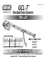
TROLLEY
NOT FOR RESIDENTIAL USE
This Installation Manual provides the information required to install, troubleshoot and
maintain a GCL-T
™
Commercial / Industrial Door Operator.
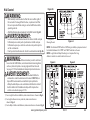
PROPER APPLICATION
Operator Type Door Type Max Door Weight/HP
Trolley Sectional 1/2HP = 1120 lbs.
(Standard, Sidemount
(Standard or Low
3/4HP = 1370 lbs.
or Dual)
Headroom Track only)
1HP = 1620 lbs.
Standard Duty Operator
GCL-T
™
111848.502351
04-14
MultiVolt®
EZ Limit®
TensiBelt®

THIS PAGE LEFT BLANK

TOC
www.geniecompany.com 01-14
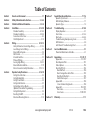
Table of Contents
Section 1 How to use this manual .................................................1.1
Section 2 Safety Information & Instructions ........................ 2.1-2.2
Section 3 Critical Installation Information ............................ 3.1-3.4
Section 4 Installation ............................................................. 4.1-4.10
Drawbar Assembly ...............................................................4.1-4.4
Drawbar Installation............................................................ 4.5-4.8
Connection to the Door ............................................................4.9
Clutch Adjustment ................................................................... 4.10
Section 5 Wiring ................................................................... 5.1-5.13
Safety Information/ Line Voltage Wiring .................... 5.1-5.2
Low Voltage Control Wiring ....................................................5.3
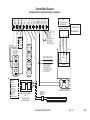
External Wire Diagram ...............................................................5.4
Wall Control ...................................................................................5.5
Interlock Switches .......................................................................5.6
Photocell Wiring ..........................................................................5.7
Sensing Edge Wiring ......................................................... 5.8-5.9
External Radio Installation .................................................. 5.10
Motor Connection/Safety Information .................. 5.11-5.13
Section 6 Operator Setup Procedures .................................. 6.1-6.10
Setting Close Direction ...............................................................6.2
Setting Braking Rate ................................................................... 6.3
Setting Travel Limits ...................................................................6.4
Setting Limit Overrun ..................................................................6.5
Monitored Reversing Devices
.............................................. 6.10
Setting Open & Close Modes ...................................................6.6
(Optional) Transmitter Programming....................................6.7
Setting Mid-Stop Limit ............................................................. 6.8
Section 7 Special Operational Features ..................................7.1-7.2
Operator Cycle Count ................................................................7.1
GDO & Display Firmware ..........................................................7.1
Operator Type...............................................................................7.2
Section 8 Troubleshooting ......................................................8.1-8.5
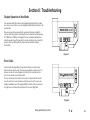
Display Operation .......................................................................8.1
Error Codes .............................................................................8.1-8.2
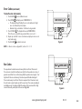
Run Codes ...............................................................................8.2-8.3
Troubleshooting Example using Codes ..............................8.3
LED Indicators ...............................................................................8.4
Safe-T-Beam® Troubleshooting Chart .................................8.5
Section 9 Service & Maintenance ................................................... 9.1
Preventive Maintenance Schedule .........................................9.1
Section 10
Appendixes ........................................................ 10.1-10.11
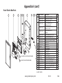
Appendix A ........................................................................10.1-10.7
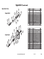
Basic Operator Parts ...............................................................10.1
Basic Shafts Parts ......................................................................10.3
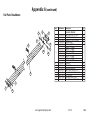
Basic Rail Parts ......................................................................10.4
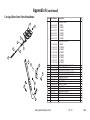
Basic Carriage/Door Arms Parts.......................................10.5
Basic Electric Box Parts ......................................................10.6
Electric Box Layout ..............................................................10.7
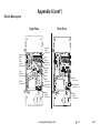
Appendix B ..................................................................................10.8
Screw Terminal Assignments ..........................................10.8
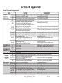
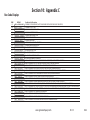
Appendix C ...................................................................... 10.9-10.11
Run Codes ...............................................................................10.9
Error Codes ...............................................................10.10-10.11
Section 11 Warranty .......................................................................11.1
Motor Options ..........................................................................10.2
Resetting the MRT ...................................................................... 6.9

Section 1: How to use this manual
The 11 sections of this Installation Manual provide the information required to install, troubleshoot and maintain an GCL-T™ commercial/industrial
door operator.
Section 2
Provides important defining information related to safety terminology used throughout this manual, as well as safety related instructions which
must be followed at all times while doing any steps/tasks/instructions detailed in this manual.
Section 3
Details pre-installation concerns/issues/decisions that are recommended to be considered and/or resolved prior to beginning any commercial door
operator installation.
Sections 4-6
eb tsum ti taht hcus nettirw si noitces hcaE .rotarepo rood laicremmoc ™T-LCG eht rof snoitcurtsni pu-tes dna noitallatsni pets yb pets edivorP
followed in a step by step order to complete a successful installation.
Sections 7-8
Detail important features and troubleshooting information for typical installation and normal operations that may occur.
Sections 9-11
Provide related information on service and maintenance items, operator drawings for use in troubleshooting and service activities, along with
important warranty and returned goods policy information.
1.1
www.geniecompany.com 04-14
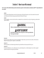
Failure to correctly perform all steps in sections 4-6 can result in serious injury or death.
WARNING
AVERTISSEMENT
Ne pas effectuer correctement toutes les étapes dans les sections 4-6 peut entraîner des
blessures graves voire la mort.

2.1
www.geniecompany.com
6
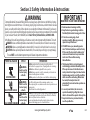
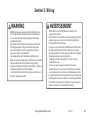
Section 2: Safety Information & Instructions
WARNING
Commercial/Industrial Sectional and Rolling Steel Doors are large, heavy objects that move with the help of springs
under high tension and electric motors. Since moving objects, springs under tension, and electric motors can cause
injuries, your safety and the safety of others depend on you reading the information in this manual. If you have any
questions or do not under stand the information presented, call your nearest service representative. For the number
of your local Genie® Dealer, call 800-OK-GENIE, and for Genie® Factory Technical Advice, call 800-843-4084.
In this Manual, the words Danger, Warning, and Caution are used to stress important safety information. The word:
DANGER
indicates an imminently hazardous situation which, if not avoided, will result in death or serious injury.
WARNING
indicates a potentially hazardous situation which, if not avoided, could result in death or serious injury.
CAUTION
indicates a potentially hazardous situation which, if not avoided, may result in injury or property damage.
The word NOTE is used to indicate important steps to be followed or important considerations.
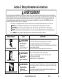
IMPORTANT
READ PRIOR TO ANY DOOR OPERATION
POTENTIAL HAZARD EFFECT PREVENTION
Do Not operate unless the doorway is in sight and free of
obstructions. Keep people clear of opening while door is moving.
Do Not allow children to play with the door operator.
Do Not change operator control to momentary contact unless an
external reversing means is installed.
Do Not operate a door that jams or one that has a broken spring.
Could result in
Serious Injury
or Death
Turn off electrical power before removing operator cover.
When replacing the cover, make sure wires are not pinched or near
moving parts.
Operator must be electrically grounded.
Do Not try to remove, repair or adjust springs or anything to which
door spring parts are fastened, such as, wood block, steel bracket,
cable or any other structure or like item.
Repairs and adjustments must be made by a trained service
representative using proper tools and instructions.
HIGH SPRING TENSION
WARNING
MOVING DOOR
1. Read manual and warnings carefully.
2. Keep the door in good working condition.
Periodically lubricate all moving parts of door.
3. If door has a sensing edge, check
operations monthly. Make any necessary
repairs to keep it functional.
4. AT LEAST twice a year, manually operate
door. The Door should open and close freely.
If it does not, the door must be taken out of
service and a trained service representative
must correct the condition causing
the malfunction.
5. The Operator Motor is protected against
overheating by an internal t
hermal protector.
If the operator ceases to function because
motor protector has tripped, a trained service
technician may need to correct the condition
which caused the overheating. When motor
has cooled, thermal protector will
automatically reset and normal operation can
be resumed.
6. In case of power failure, the door can be
operated manually by pulling the release
cable to disconnect the operator drive system.
7. Keep instructions
in a prominent location
near the pushbutton.
Could result in
Serious Injury
or Death
WARNING
Could result in
Serious Injury
or Death
WARNING
ELECTRICAL SHOCK

2.2
Section 2: Safety Information & Instructions
www.geniecompany.com 04-14
AVERTISSEMENT
Les portes de garage commerciales/industrielles à sections et en acier roulantes sont de gros objets lourds qui fonctionnent à l’aide de ressorts soumis à une haute tension et
de moteurs électriques. Dans la mesure où les objets en mouvement, les ressorts sous tension et les moteurs électriques peuvent entraîner des blessures, votre sécurité et celle
des autres exigent que vous preniez connaissance des informations stipulées dans ce manuel. Si vous avez des questions ou si vous ne comprenez pas les informations
ci-incluses, veuillez contacter le représentant de service le plus près. Pour obtenir le numéro du revendeur Genie® local, appelez le +1 (800)-OK-GENIE, et pour obtenir
des conseils techniques de l'usine Genie®, appelez le +1 (800)-843-4084.
Dans ce manuel, les mots Danger, Avertissement, et Attention sont utilisés pour faire ressortir d’importantes informations relatives à la sécurité. Le mot :
DANGER
signale une situation dangereuse imminente qui si elle n'est pas évitée, risque d'entraîner des blessures graves, voire mortelles.
Le terme REMARQUE est utilisé pour signaler les étapes importantes à suivre ou d’importants éléments à prendre en considération.
DANGER POTENTIEL
EFFET
PRÉVENTION
Utiliser uniquement si la porte est en vue et libre de tout obstacle. Ne laisser personne
se tenir dans l’ouverture de la porte pendant qu’elle est en mouvement.
Ne pas permettre aux enfants de jouer avec l’opérateur de la porte.
Ne pas modifier la commande de l'opérateur à contact momentané à moins qu'un moyen
d'inversion externe soit installé.
Ne pas faire fonctionner une porte qui bloque ou dont le ressort est cassé.
Pourrait entraîner
des blessures
graves voire la mort
AVERTISSEMENT
Pourrait entraîner
des blessures
graves voire la mort
CHOC ÉLECTRIQUE
TENSION ÉLEVÉE DU RESSORT
PORTE EN MOUVEMENT
ATTENTION
signale une situation potentiellement dangereuse qui, si elle n'est pas évitée, risque d'entraîner des blessures ou des dommages matériels.
AVERTISSEMENT
signale une situation potentiellement dangereuse qui, si elle n'est pas évitée, risque d'entraîner la mort ou des blessures graves.
Pourrait entraîner
des blessures
graves voire la mort
Couper le courant avant d’enlever le couvercle de l'opérateur.
Lorsque le couvercle doit être remplacé, s’assurer que les fils ne sont ni
coincés ni près des pièces mobiles.
L’opérateur doit être correctement mis à la terre.
Ne pas essayer d’enlever, réparer ni ajuster les ressorts ou toute autre pièce à laquelle le
ressort de la porte est attaché, y compris blocs de bois, supports en acier, câbles ou autres
articles semblables.
Les réparations et les réglages doivent être effectués par technicien qualifié qui se sert
d’outils appropriés et qui respecte les instructions.
AVERTISSEMENT
AVERTISSEMENT

3.1
www.geniecompany.com 04-14
Job
Site Issues to Consider/Concerns
The following list of items should be considered prior to selecting an operator for a given job site.
1-Available power supply.
2-Type of door.
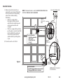
3-Potential operator mounting obstructions. Items to consider include, but are not limited to: side room, room above door shaft,
room below door shaft, available mounting
surface integrity, power supply location, and convenient chain hoist and release cable positioning.
4-Size of door for appropriate
operator torque and door travel speed selection.
dustiness 5-Operator mounting environment. Items to consider include operator location and dampness,
and corrosiveness of the location.
6-Door activation needs/requirements. Examples include 3
button control stations, 1 button control stations, radio controls, pull
cords,
loop detectors, photoelectric controls,
key switches, etc. See “Entrapment Protection” section below.
7-Interlock switches are required under certain conditions for
doors with pass doors and door locks. See page 5.6.
8-Accessory equipment. Example
s are reversing edges and/or photocell beams (required for
doors set to operate as momentary contact,), auxiliary control relays, warning lights, etc.
Section
3:
Critical
Installation
Information
ENTRAPMENT PROTECTION
The installation of a fail safe external reversing device (such as a monitored reversing edge or photocell system, etc.) is required on all momentary contact electronically
operated commercial doors. If such a reversing device is not installed, the operator will revert to a constant contact control switch for operation (Closing only).
The Reversing Devices currently UL Approved are:
MillerEdge ME and MT series monitored edge sensors used in combination with Timer-Close Module P/N OPABTCGX.S
MillerEdge ME and MT series monitored edge sensors used in combination with MillerEdge Interface Module OPAKMEIGX.S. (Direct connect through STB inputs.)
4)
Residential Safe-T-Beam® Monitored Photocells - P/N 37220R (GSTB-BX) & 38176R.S (includes extension brackets).
5)
Series II Commercial Safe-T-Beam® Monitored Photocells - P/N OPAKPE.S and OPAKPEN4GX.S (NEMA 4).
1)
2)
6) Monitored Retro-Reflective Photoeye - P/N OPGAKRPEN4X.S
MillerEdge Wireless monitored edge sensor OPAKMMWE.S.
3)
WARNING:
DO NOT apply line voltage until instructed to do so.
AVERTISSEMENT:
NE PAS mettre sous tension tant que l'instruction n'est pas donnée de le faire.

3.2
www.geniecompany.com 04-14
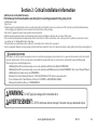
Section
3: Critical Installation Information
CAUTION:
Check working condition of door before installing the operator. Door must be free from sticking and binding.
If equipped, deactivate any door locking device(s). Door repairs and adjustments, including cables and spring assemblies MUST
be made by a trained service representative using proper tools and instructions.
ATTENTION:
Vérifiez l'état de fonctionnement de la porte avant d'installer l'opérateur.
La porte doit pouvoir bouger librement et ne pas coincer. Désactivez tous les dispositifs de verrouillage de la porte (si équipés).
Les réparations et les réglages de porte, plus particulièrement pour les câbles et les ressorts DOIVENT être effectués par un
technicien qualifié qui se sert d’outils appropriés et qui respecte les instructions.
Mult
— Offers all (available) voltage combinations in both single, and 3-phase units.
E
TensiBelt
®
Z Limit
®
— F
— Employs a self-adjustment feature for tensioning.
eatures patent pending electro-mechanical design that sets limits through the control panel that are maintainable even through a power outage.
New Features:
MultiVolt
®

3.3
www.geniecompany.com 01-14
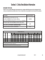
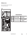
ENTRAPMENT PROTECTION
The GCL-T™ can be used with the following UL Listed entrapment devices in compliance with UL325 requirements active starting August 29, 2010.
UNTIL ONE OF THESE MONITORED EXTERNAL ENTRAPMENT DEVICES IS INSTALLED, TH WILL NOT ALLOW MOMENTARY CONTACT OPERATION IN THE CLOSE DIRECTION.
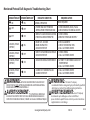
Section 3: Critical Installation Information
Type
Mounting
Max.
Door
Weight
(Lbs)
16GA.
Flush
Steel
16GA.
Flush
Steel
Insulated
20GA.
Ribbed
Steel
20GA.
Ribbed
Steel
Insulated
24GA.
Ribbed
Steel
24GA.
Ribbed
Steel
Insulated
Nominal
24GA.
Ribbed
Steel
Nominal
24GA.
Ribbed Steel
Insulated
Insulated
PU/FIP
Insulated
PU/FIP
1.38"
1/8" Glass
1.38"
Glass
1.38"
Insulated
PU/FIP
2"
Insulated
PU/FIP
2"
20GA.
Yes TSC 1120 256 220 370 256 440 340 320 320 256 360 400 300 400 380 360 240
TSC 1370 330 256 440 310 530 400 320 320 256 450 450 370 460 440 400 330
TSC 1620 380 280 500 370 570 410 320 320 256 480 480 420 500 480 400 400
Yes
Yes
UL Lis tedHPModel
T=Trolley
Aluminum
Do
or S eries ->
Note: Total door weight, and not the square footage, is the critical factor in selecting the proper operator.
Square footage measurements are based on "square doors." (Example=16' x 16')
NOTE: Doors that require special windloading and wide doors, normally require increased strutting (reinforcement). Strutting doors can significantly increase door
weight beyond weight shown. Consult Customer Service for the impact of wind load andstrutting on square foot limits.
NOTE: "PU-FIP" stands for "polyurethane, foamed-in-place." If no notation is present, insulation is "polystyrene, layed-in-place."
Sectional Door Chart (sq. ft.)
GCL-T™ 1/2
GCL-T™ 3/4
GCL-T™ 1
216 216 ins. 220 220 ins. 2415 2415 ins. 2411 2411 ins. 125 150 200 200-20 5150 5200 451 452
CommercialSteelInsulated&Non-Insulated Thermospan Thermomark
Exterior
Insulated
PU/FIP
Raised
Panel
1.38"
Insulated
1/4" or 1/2"
PU/FIP
Raised
Panel
2"
E OPERATOR
Miller Edge ME & MT series monitored edge sensors used in
combination with OPABTCGX.S Timer-Close Module or MillerEdge
Interface Module OPAKMEIGX.S. Miller Edge Wireless monitored edge sensor OPAKMMWE.S
ANY WIDTH
Residential Safe-T-Beams® P/N 37220R (GSTB-BX) and 38176R.S (includes ext. brkt’s)
Commercial Photoeye Kit P/N OPAKPE.S and OPAKPEN4GX.S (NEMA 4)
LISTED DEVICES
ALLOWABLE DOOR WIDTH
30 FEET
35 FEET
Monitored Retro-Refective Photoeye Kit P/N OPGAKRPEN4X.S

3.4
www.geniecompany.com 04-14
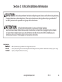
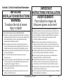
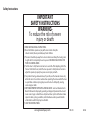
IMPORTANT
INSTALLATION INSTRUCTIONS
WARNING-
To reduce the risk of severe
injury or death:
READ AND FOLLOW ALL INSTALLATION INSTRUCTIONS.
Install only on a properly operating and balanced door. A door that is
operating improperly could cause severe injury. Have qualified service
personnel make repairs to cables, spring assemblies and other
hardware before installing the operator.
Remove all pull ropes and remove, or make inoperative, all locks
(unless mechanically and/or electronically interlocked to the power
unit) that are connected to the door before installing the operator.
Install the door operator at least 8 feet above the floor if the operator
has exposed moving parts.
Do not connect the door operator to the power source until
instructed to do so.
Locate the control station: (a) within sight of the door, (b) a minimum
of 5 feet above the floor so that small children cannot reach it, and
(c) away from all moving parts of the door.
Install the Entrapment Warning Placard next to the control station
and in a prominent location.
For products having a manual release, instruct the end user on the
operation of the manual release.
IMPORTANT
INSTRUCTIONS D’INSTALLATION
AVERTISSEMENT-
Pour réduire les risques de
blessures graves ou de mort :
1)
LIRE ET RESPECTER TOUTES LES INSTRUCTIONS D'INSTALLATION.
2)
Installez uniquement sur une porte fonctionnant correctement et bien
équilibrée. Une porte qui fonctionne mal peut provoquer des blessures
graves. Demandez à un technicien qualifié d'effectuer les réparations
des câbles, des ressorts et de toute autre quincaillerie avant de
procéder à l'installation de l'opérateur.
Retirez toutes les cordes de traction ainsi que tous les verrous ou
rendez-les inopérants (à moins qu'ils ne soient mécaniquement et/ou
électroniquement interverrouillés à l'unité motrices) qui sont connectés
à la porte avant de procéderà l'installation de l'opérateur.
Installez l'opérateur de la porte à 2,4 m minimum au-dessus du sol
lorsque des pièces mobiles de l'opérateur sont exposées.
Ne pas raccorder l'opérateur de la porte à la source d’alimentation
avant que l'instruction ne soit donnée de le faire.
Installez la station de commande : (a) en vue de la porte, (b) à 1,5 m
minimum au-dessus du sol pour que les jeunes enfants ne puissent
pas l'atteindre, et (c) à l'écart de toutes les pièces mobiles de la porte.
Installez le poster d'avertissement de pincement à côté de la station de
commande à un endroit bien en vue.
Pour les produits ayant un déclenchement manuel, indiquez à l'utilisateur
comment déclencher manuellement.
3)
4)
5)
6)
7)
8)
1)
2)
3)
4)
5)
6)
7)
8)
Section 3: Critical Installation Information

4.1
www.geniecompany.com 04-14
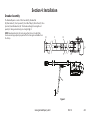
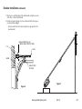
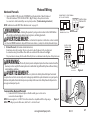
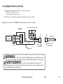
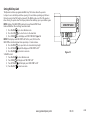
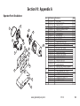
The Drawbar Operator consists of the Power Unit (A), Drawbar Rail
(B), Chain Guides (C), Front Spreader (D), Front Idler Pulley (E), Drive Chain (F), Drive
Sprocket (G) and Drawbar Arm (H). The Drawbar rail length, chain length and
quantity of chain guides will vary by door heights. Fig. 1.
Section 4: Installation
Drawbar Assembly
NOTE: Drawbar rail must be (29) inches longer than the door’s height. Rails
have been sized properly and pre-punched for the chain guide assemblies from
the factory.
Figure 1
A
B
G
F
C
E
D
H

4.2
www.geniecompany.com 04-14
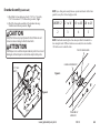
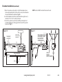
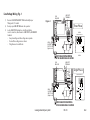
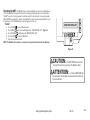
Drawbar Assembly (continued)
1) Attach Rails to Power Unit using four (4) 7/16”-14 x 1” hex bolts,
7/16”-14 hex nuts and 7/16” lock washers (provided). Fig. 2.
2) Attach the chain guide assemblies to the drawbar rails using
Track Bolts and locknuts (provided). Fig. 3.
Figure 3
CHAIN GUIDE BRACKET
TRACK BOLTS/
LOCKNUTS
PLASTIC CHAIN GUIDE
NOTE: Space chain guides evenly between operator and header. Add a chain
guide for every 4 feet of door height per chart.
NOTE: Chain Guide mounting holes have been pre-drilled at standard loca-
tions along the track. If different locations are needed, hole size should be
1/4" dia. Be sure to de-burr the holes.
UNDER 12’
12’ to 16’ 16’ to 20’ 20’ to 24’
2 3 4 5
Figure
2
7/16" HEX
BOLTS
CAUTION
Verify that screws are properly seated in track. Failure to seat
screws can cause carriage to bind in door track
Vérifiez que les vis sont bien en place dans la piste. Si les vis sont
mallogées, le chariot peut se coincer dans la piste de la porte.
ATTENTION

4.3
www.geniecompany.com 01-14
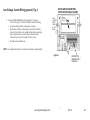
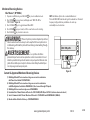
Drawbar Assembly (continued)
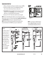
3) Insert the carriage into the rails as shown in Fig. 4.
NOTE: The end of the carriage with the chain tension adjustment bolt should be
toward the operator.
4) Place the spreader bracket in position around the drawbar rail. Do not
redaerps ehT .emit siht ta stun kcol dna stlob kcart eht tresni
bracket
will be held in place (temporarily) by the idler pin which holds
the pulley.
RAIL
Figure 4
Figure 5
FRONT
SPREADER
BRACKET
WASHER
COTTER PIN
IDLER PIN
IDLER PULLEY
/STLOB KCART
LOCKNUTS
DO NOT INSTALL YET!
SLEEVE
OPERATOR
DOOR
CARRIAGE
5) Install the idler pulley inside the track by inserting the 7/16” x 7” idler
pin through one side of the track and as you feed it through an idler
sleeve and the idler pulley followed by the second sleeve . Place fender
washer (7/16” x 1-1/4”) over each end of idler pin. Secure idler pin by
inserting a cotter pin through the hole in each end of idler pin. Fig. 5.
NOTE: For building of the spreader bracket assembly on a Dual Trolley or
Sidemount Trolley unit, see the separate Drawbar instruction sheet for
Sidemount and Dual Trolley models.
WASHER &
COTTER PIN
THIS SIDE

4.4
www.geniecompany.com 04-14
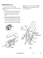
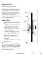
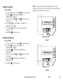
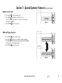
6) Uncoil the drawbar chain and install by routing the chain over the chain
guides (A) and around the drive sprocket (B) on the output shaft as shown
in Fig. 6.
7) Attach to Chain Tension Adjusting Bolt (C) using a master link (provided).
8) Pass the other end of the chain between the front spreader bracket and
the idler pulley (D). Make certain the chain is not twisted.
9) Attach the chain to the carriage (E) using a master link.
10) Insert the Adjusting Bolt through the hole in the Carriage and place the
tensioning spring, flat washer and adjusting nut onto the bolt. Detail A,
Fig 6.
11) Tighten Chain so that it will not jump a sprockets or pulley. Add locknut.
Check to ensure the following:
• The chain is properly engaging the output sprocket.
• The chain is not twisted.
Drawbar Assembly (continued)
Detail A
CHAIN
TENSION
ADJUSTMENT
SCREW
FLAT WASHER
LOCKNUT
ADJUSTING NUT
TENSIONING
SPRING
MASTER
LINK
MASTER
LINK
Figure 6
A
A
C
D
E
B
•
DO NOT apply line voltage until instructed to do so.
WARNING
•
NE PAS mettre sous tension tant que l'instruction n'est
pas donnée de le faire.
AVERTISSEMENT

4.5
www.geniecompany.com 04-14
Drawbar Installation
•
Repairs and adjustments, including particularly to cables and
spring assemblies under high tension, must be made by a
trained service representative using proper tools and instructions.
WARNING
•
Les réparations et les réglages, plus particulièrement aux câbles
et ensembles de ressort sous tension élevée doivent être
effectués par un professionnel qui se sert d’outils appropriés
et qui respecte les instructions.
AVERTISSEMENT
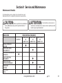
CAUTION
Check the working condition of the door before installing the operator.
The Door must be free from sticking and binding. If the door is equipped
with a latching device, secure the locking bar in the open (unlocked)
position. This style operator will act as a latching device when the door
is down and therefor the door’s lock is no longer needed.
If the door lock is to remain functional, an interlock switch MUST be
installed which will prevent operation of the door whenever the door
lock is engaged. Refer to the Wiring Instructions, section 5, of this
manual for proper connection of the interlock switch.
ATTENTION
Vérifiez l'état de fonctionnement de la porte avant d'installer l'opérateur.
La porte doit pouvoir bouger librement. Si la porte est équipée d'un
dispositif de verrouillage, fixez la barre de verrouillage en position
ouverte (déverrouillée). Cet opérateur agit comme un dispositif de
verrouillage lorsque la porte est en bas et que le verrouillage de la
porte n'est donc plus nécessaire.
Si le verrouillage de la porte doit rester fonctionnel, un commutateur de
verrouillage DOIT être installé pour empêcher le fonctionnement de la
porte chaque fois que le verrouillage de la porte est engagé. Reportez-
vous aux instructions de câblage, section 5, de ce manuel pour établir
une connexion correcte de l'interrupteur de verrouillage.

4.6
www.geniecompany.com 04-14
VERTICAL LINE
(SEE STEP 1)
HEADER
ATTACHMENT MATERIAL
(SEE STEP 2)
HORIZONTAL LINE
(SEE STEP 6)
CENTERLINE
OF DOOR
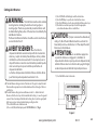
1) Measure the width of the door to determine the center. Make a vertical
line above the door, as shown in Fig. 7. (If the vertical line is not in line
with a door stile, a means of attaching the door bracket to the door must
be provided. This can be accomplished by spanning the center of the
door’s top section (between the top and bottom rail) with a suitable
material such as wood or steel).
2) Prepare for attaching drawbar to header. If woodwork, or other suitable
material is not already in place, securely affix a 2” x 6” block of wood or
metal plate as shown in Fig. 7.
3) Center the block/plate on the header.
4) Mark the door’s vertical center line on this block/plate.
5) Use a level, as shown in Fig. 8 (pg 4.6) to find the highest point of travel for
the door.
6) Mark a horizontal line across the vertical line you made on the header
at 5” above the highest point of door travel.
Drawbar Installation (continued)
Figure 7
NOTE: On torsion spring doors with an uneven number of panels, the operator
may be attached to the stile nearest to the center.

4.7
www.geniecompany.com 04-14
Drawbar Installation (continued)
2" X 6"
HEADER
MARK A HORIZONTAL LINE
5"
ABOVE HIGHEST POINT OF TRAVEL
LEVEL
HIGHEST POINT
OF TRAVEL
Figure 8
Figure 9
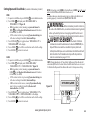
7) Raise the door end (idler pulley) of the drawbar while resting the operator
on the floor or other desired material.
8) Position the spreader bracket on your centerline with its bottom edge on
your horizontal mark. Fig. 9.
• Fasten spreader bracket to header using fasteners appropriate for the
header material.

4.8
www.geniecompany.com 01-14
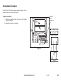
1) Raise the operator and position it so that the drawbar rails are
level and perpendicular to the face of the door (or the stile where
the door bracket will be attached). Fig. 10.
2) Lock the drawbar rails into the spreader bracket using the
two (2)
track bolts (1/4”-20 X 9/16”) and two(2) locknuts.
3) Secure the operator in position by installing steel angles (not
provided) between the ceiling superstructure and the operator
power unit. Fig. 11.
Drawbar Installation (continued)
TRACK BOLTS
& LOCK NUTS
ROPE, CABLE,
CHAIN, ETC.
LEVEL
WALL WALL
RAILS
90°
DOOR FROM ABOVE
Figure 10
DRILL HOLE IN ANGLE
AND MOUNT USING
REAR SUPPORT
CARRIAGE BOLT
STEEL
ANGLES
(NOT INCLUDED)
Figure 11
NOTE: Track bolts MUST be installed from inside the rails.

4.9
TM
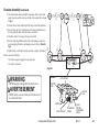
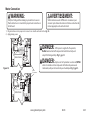
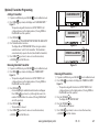
1) Pull down on the drawbar arm locking sleeve and attach to carriage. (See NOTE 2.)
2) Position the door bracket on the door as shown in Fig. 12, with mounting
. )rellor rood pot evoba ro htiw nevE( .enilretnec rood eht no seloh
3) For wood doors fasten the door bracket to the door using two 1/4” -20 X 2-1/4”
carriage bolts and nuts. For metal doors use two 1/4”- 20 self tapping sheet
metal screws, or as recommended by the door manufacturer.
4) Use two (2) 3/8” -16 X 7/8” bolts and nuts to attach the door arms together.
NOTE: Use the set of holes that align the drawbar in a near vertical position for operators
without a brake. Set arms at a 20-30 degree rearward angle for operators with a brake.
Fig. 13.
For units without a brake, set arms as close to 0 degrees (vertical) as
possible.
NOTE: If the door strut interferes with the mounting of the door bracket, position
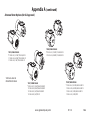
NOTE 2: In case of emergency, pulling the Emergency
Release Knob (Fig. 13) disengages the door from the
operator allowing for manual operation of the door.
the door bracket below the strut. DO NOT, in any way, cut or modify the strut.
Connection to the Door
Figure 13
Figure 12
20°-30°
with Brake
When installing non-brake units
with drawbar near vertical, it is
important to make sure there
is adequate room between the
door bracket and drawbar rail
for the door arms to go vertical.
Without sufficient clearance
and by running the dood arms
vertical, a significant amount of
force could be applied possibly
leading to damage.
There is an optional drawbar
kit with a cusion springbox
available: P/N OPAKDBT.S
WITH BRAKE WITHOUT BRAKE
AVOID THIS SETUP
WITHOUT BRAKE
CORRECT
www.geniecompany.com 01-14

4.10
www.geniecompany.com 01-14
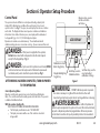
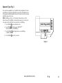
The Operators have a friction style clutch that can be adjusted.
NOTE: The clutch is intended to provide protection for the door, the operator and
associated equipment. It is not intended for entrapment protection. Trolley
operators have a motor reversing feature that is integrated with the clutch
assembly. If an obstruction is placed in the pathway of the door during operation
the motor will stop and reverse when the clutch begins to slip.
The adjustment of the clutch should be such that the door and operator function in
this manner. The steps for clutch adjustment follow:
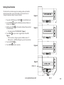
To Adjust the Clutch
1) Decrease the compression on the clutch until the operator will not lift
the door.
• Turn the adjusting castle nut counter-clockwise to decrease clutch
compression and clockwise to increase clutch compression.
2) After completing step 1, begin to increase compression on the
clutch until the operator is capable of
lifting the door through the
complete cycle without clutch slippage.
3) Test the reversing feature of the operator by placing an obstruction
under the door during a close cycle. The door should reverse on the
obstruction and return to the open position. If the door does not
close but comes down part way and reverses without any
obstructions in its path, then increase the clutch compression until
the door will close fully.
4) Finally, insert the cotter pin through the castle nut and shaft and bend
the outer leg of the cotter pin.
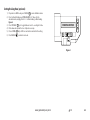
NOTE:
Periodically check the system for proper clutch action. If clutch starts to slip after
working properly for some time, check manual operation of door BEFORE adjusting
clutch. The door may not be operating freely or the counterbalance spring may
need adjusting. Repairs and adjustments must be performed by a trained service
representative using proper tools and instructions.
Clutch Adjustment Fig. 14
CLUTCH PULLEY
WASHER
COTTER PIN
ADJUSTING NUT
CLUTCH
PAD
CLUTCH
PLATE
SPRING
Figure 14
La page est en cours de chargement...
La page est en cours de chargement...
La page est en cours de chargement...
La page est en cours de chargement...
La page est en cours de chargement...
La page est en cours de chargement...
La page est en cours de chargement...
La page est en cours de chargement...
La page est en cours de chargement...
La page est en cours de chargement...
La page est en cours de chargement...
La page est en cours de chargement...
La page est en cours de chargement...
La page est en cours de chargement...
La page est en cours de chargement...
La page est en cours de chargement...
La page est en cours de chargement...
La page est en cours de chargement...
La page est en cours de chargement...
La page est en cours de chargement...
La page est en cours de chargement...
La page est en cours de chargement...
La page est en cours de chargement...
La page est en cours de chargement...
La page est en cours de chargement...
La page est en cours de chargement...
La page est en cours de chargement...
La page est en cours de chargement...
La page est en cours de chargement...
La page est en cours de chargement...
La page est en cours de chargement...
La page est en cours de chargement...
La page est en cours de chargement...
La page est en cours de chargement...
La page est en cours de chargement...
La page est en cours de chargement...
La page est en cours de chargement...
La page est en cours de chargement...
La page est en cours de chargement...
La page est en cours de chargement...
La page est en cours de chargement...
La page est en cours de chargement...
La page est en cours de chargement...
La page est en cours de chargement...
-
 1
1
-
 2
2
-
 3
3
-
 4
4
-
 5
5
-
 6
6
-
 7
7
-
 8
8
-
 9
9
-
 10
10
-
 11
11
-
 12
12
-
 13
13
-
 14
14
-
 15
15
-
 16
16
-
 17
17
-
 18
18
-
 19
19
-
 20
20
-
 21
21
-
 22
22
-
 23
23
-
 24
24
-
 25
25
-
 26
26
-
 27
27
-
 28
28
-
 29
29
-
 30
30
-
 31
31
-
 32
32
-
 33
33
-
 34
34
-
 35
35
-
 36
36
-
 37
37
-
 38
38
-
 39
39
-
 40
40
-
 41
41
-
 42
42
-
 43
43
-
 44
44
-
 45
45
-
 46
46
-
 47
47
-
 48
48
-
 49
49
-
 50
50
-
 51
51
-
 52
52
-
 53
53
-
 54
54
-
 55
55
-
 56
56
-
 57
57
-
 58
58
-
 59
59
-
 60
60
-
 61
61
-
 62
62
-
 63
63
-
 64
64


Genie GCL-T Operator / Installation Manual
- Catégorie
- Porte de garage
- Taper
- Operator / Installation Manual
dans d''autres langues
- English: Genie GCL-T
Documents connexes
-
Genie GCL-GT Operator / Installation Manual
-
Genie GCL-GH Operator / Installation Manual
-
Genie GCL-J&H 1HP Guide d'installation
-
-
-
-
Genie GCL-MT Manuel utilisateur
-
-
-