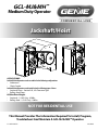
Genie GCL-MJ / GCL-MH Operator / Installation Manual
- Catégorie
- Porte de garage
- Taper
- Operator / Installation Manual

NOT FOR RESIDENTIAL USE
Jackshaft/Hoist
02/2018111852.503517
This Manual Provides The Information Required To Install, Program,
Troubleshoot And Maintain A GCL-MJ & MH™ Operator.
Jackshaft/Hoist Operators can be assembled in the following congurations:
• Sidemount
• ChainCouple
Jackshaft/Hoist Operators can be installed on the following types of doors:
• SectionalDoors-VerticalLift,LiftClearanceType
• RollingSteelDoors
APPLICATIONS:
HP/Max Door Weight:
• Sectional-1/2HPOnly-620lbs.
• RollingSteel-1/2HPOnly-580lbs.
Medium Duty Operator
GCL-MJ&MH
™

INDEX
SECTION 1:
GeneralInformation&Instructions........................................................................................................................ 1.1
SafetyInformation&Instructions.....................................................................................................................1.2-1.3
CriticalInstallationInformation-General............................................................................................................ 1.4
CriticalInstallationInformation-EntrapmentProtection.............................................................................. 1.5
SECTION 2: Operator Installation
RollingSteel-FrontofHood..............................................................................................................................2.1-2.2
RollingSteel-WallMount.......................................................................................................................................... 2.3
Sectional-ChainCouple......................................................................................................................................2.4-2.6
Clutch&BrakeAdjustment........................................................................................................................................ 2.7
Handwheel&Keeper.................................................................................................................................................... 2.8
SECTION 3: Operator Wiring
WiringSafetyInformation.......................................................................................................................................... 3.1
GeneralInternalWireDiagram................................................................................................................................. 3.2
LineVoltage..................................................................................................................................................................... 3.3
LowVoltage..................................................................................................................................................................... 3.4
WallControls............................................................................................................................................................3.5-3.6
AccessoryOverview...................................................................................................................................................... 3.7
Interlocks,SectionalDoors......................................................................................................................................... 3.8
Photocells............................................................................................................................................................... 3.9-3.10
SensingEdge,Hardwire............................................................................................................................................3.11
SensingEdge,Wireless..............................................................................................................................................3.12
SensingEdge,HardwirewithExpansionBoard................................................................................................3.13
OptionalRadioControls............................................................................................................................................3.14
SECTION 4: Operator Programming and Menus
SafetyInformation......................................................................................................................................................... 4.1
ControlPanel&Display............................................................................................................................................... 4.2
ConstantContact........................................................................................................................................................... 4.3
TravelLimits..................................................................................................................................................................... 4.4
LimitOverrun.................................................................................................................................................................. 4.5
MonitoredReversingDevices................................................................................................................................... 4.6
MaxRunTimer(MRT)................................................................................................................................................... 4.7
Mid-Stop........................................................................................................................................................................... 4.8
Open&CloseModes.................................................................................................................................................... 4.9
SPECIAL FEATURES:
CycleCounter................................................................................................................................................................4.10
GDOVersion&Firmware...........................................................................................................................................4.10
GDOType........................................................................................................................................................................4.10
TransmitterProgramming........................................................................................................................................4.11
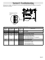
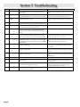
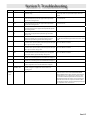
SECTION 5: Troubleshooting
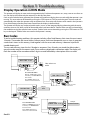
TroubleshootingLED’s................................................................................................................................................. 5.1
RunModeDetails.......................................................................................................................................................... 5.2
RunCodeChart.............................................................................................................................................................. 5.3
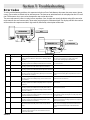
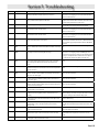
ErrorCodes................................................................................................................................................................5.4-5.7
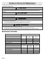
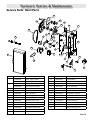
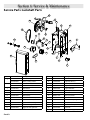
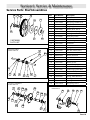
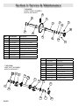
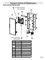
SECTION 6: Service & Maintenance
Service&MaintenanceSchedule............................................................................................................................ 6.1
PartsBreakDowns..................................................................................................................................................6.2-6.6
WARRANTY

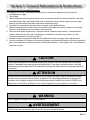
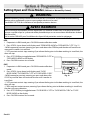
Checkworkingconditionofdoorbeforeinstallingtheoperator.Doormustbefreefromstickingand
binding.Ifequipped,deactivateanydoorlockingdevice(s).Doorrepairsandadjustments,including
cablesandspringassembliesMUSTbemadebyatrainedservicerepresentativeusingpropertoolsand
instructions.
CAUTION
!
ATTENTION
!
Vériezl’étatdefonctionnementdelaporteavantd’installerl’opérateur.Laportedoitpouvoirbouger
librementetnepascoincer.Désactiveztouslesdispositifsdeverrouillagedelaporte(siéquipés).Les
réparationsetlesréglagesdeporte,plusparticulièrementpourlescâblesetlesressortsDOIVENTêtre
eectuésparuntechnicienqualiéquisesertd’outilsappropriésetquirespectelesinstructions.
DONOTapplylinevoltageuntilinstructedtodoso.
WARNING
!
AVERTISSEMENT
!
NEPASmettresoustensiontantquel’instructionn’estpasdonnéedelefaire.
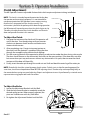
Job Site Issues to Consider/Concerns
Thefollowinglistofitemsshouldbeconsideredpriortoselectinganoperatorforagivenjobsite.
1. Availablepowersupply.
2. Typeofdoor.
3. Potentialoperatormountingobstructions.Itemstoconsiderinclude,butarenotlimitedto:sideroom,
roomabovedoorshaft,roombelowdoorshaft,availablemountingsurfaceintegrity,powersupply
location,andconvenientchainhoistandreleasecablepositioning.
4. Sizeofdoorforappropriateoperatortorqueanddoortravelspeedselection.
5. Operatormountingenvironment.Itemstoconsiderincludeoperatorlocation,dampnessoflocation,
dustinessofthelocationandcorrosivenessofthelocation.
6. Dooractivationneeds/requirements.Examplesinclude3buttoncontrolstations,1buttoncontrol
stations,radiocontrols,pullcords,loopdetectors,photoelectriccontrols,keyswitches,etc.See
“EntrapmentProtection”sectiononpage1.5.
7. Interlockswitchesarerequiredundercertainconditionsfordoorswithpassdoorsanddoorlocks.
8. Accessoryequipment.Examplesincludereversingedgesand/orphotocellbeams,whicharerequiredfor
doorssettooperateasmomentarycontact,auxiliarycontrolrelays,warninglights,etc.See“Entrapment
Protection”section.
Section 1: General Information & Instructions
Sec-1.1

Sec-1.2
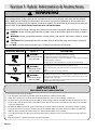
Section 1: Safety Information & Instructions
POTENTIAL HAZARD EFFECT PREVENTION
MOVING DOOR
WARNING
CouldresultinSerious
InjuryofDeath
DoNotoperateunlessthedoorwayisinsightandfreeofobstructions.
Keeppeopleclearofopeningwhiledoorismoving.
DoNotallowchildrentoplaywiththedooroperator.
DoNotchangeoperatorcontroltomomentarycontactunlessandexternal
reversingmeansisinstalled.
DoNotoperateadoorthatjambsoronethathasabrokenspring.
ELECTRICAL SHOCK
WARNING
CouldcauseSerious
InjuryorDeath
Turnoelectricalposerbeforeremovingoperatorcover.
Whenreplacingthecover,makesurewiresarenotpinchedornearmoving
parts.
Operatormustbeelectricallygrounded.
HIGH SPRING TENSION
WARNING
CouldcauseSerious
InjuryorDeath
DoNottrytoremove,repairoradjustspringsoranythingtowhichdoor
springpartsarefastened,suchaswoodblock,steelbracket,cableorany
otherstructureorlikeitem.
Repairsandadjustmentsmustbemadebytrainedservicerepresentative
usingpropertoolsandinstructions.
!
!
!
WARNING
OverheadDoorsarelarge,heavyobjectsthatmovewiththehelpofspringsunderhightensionandelectricmotors.
Sincemovingobjects,springsundertension,andelectricmotorscancauseinjury,yoursafetyandthesafetyof
othersdependonyoureadingtheinformationinthismanual.Ifyouhaveanyquestionsordonotunderstand
theinformationpresented,callyournearestservicerepresentative.ForthenumberofyourlocalGenieDealer,call
800-OK-GENIE,andfor Genie Factory Technical Advice, call 800-843-4084.
InthismanualthewordsDanger,Warning,andCautionareusedtostressimportantsafetyinformation.Theword:
DANGERindicatesanimminentlyhazardoussituationwhich,ifnotavoided,willresultindeathorserious
injury.
WARNINGindicatesapotentiallyhazardoussituationwhich,ifnotavoided,couldresultindeathorserious
injury.
CAUTIONindicatespotentiallyhazardoussituationwhich,ifnotavoided,mayresultininjuryorproperty
damage.
ThewordNOTE, is used to indicate important steps to be followed or important considerations.
!
!
!
!
1. Readmanualandwarningscarefully.
2. Keepthedooringoodworkingcondition.Periodicallylubricateallmovingpartsofdoor.
3. Ifdoorhasasensingedge,checkoperationsmonthly.Makeanynecessaryrepairstokeepitfunctional.
4. ATLEASTtwiceayear,manuallyoperatethedoorbydisconnectingitfromtheoperator.TheDoorshouldopenandclose
freely.Ifitdoesnot,thedoormustbetakenoutofserviceandatrainedservicerepresentativemustcorrectthecondition
causingthemalfunction.
5. TheOperatorMotorisprotectedagainstoverheatingbyaninternalthermalprotector.Ifthemotorprotectoristripped,
atrainedservicetechnicalmaybeneededtocorrecttheconditionwhichcausedtheoverheating.Whenthemotorhas
cooled,thermalprotectorwillautomaticallyresetandnormaloperationcanberesumed.
6. Incaseofpowerfailure,thedoorcanbeoperatedmanuallybypullingthereleasecabletodisconnecttheoperatordrive
system.
7. Keepinstructionsinaprominentlocationnearthepushbutton.
IMPORTANT
READ PRIOR TO ANY DOOR OPERATION

Sec-1.3
DANGER POTENTIEL EFFET PRÉVENTION
PORTE EN MOUVEMENT
AVERTISSEMENT
Pourraitentraînerdes
blessuresgravesvoirela
mort
Utiliseruniquementsilaporteestenvueetlibredetoutobstacle.Ne
laisserpersonnesetenirdansl’ouverturedelaportependantqu’elleesten
mouvement.
Nepaspermettreauxenfantsdejoueravecl’opérateurdelaporte.
Nepasmodierlacommandedel’opérateuràcontactmomentanéàmoins
qu’unmoyend’inversionexternesoitinstallé.
Nepasfairefonctionneruneportequibloqueoudontleressortestcassé.
CHOC ÉLECTRIQUE
AVERTISSEMENT
Pourraitentraînerdes
blessuresgravesvoirela
mort
Couperlecourantavantd’enleverlecouvercledel’opérateur.
Lorsquelecouvercledoitêtreremplacé,s’assurerqueleslsnesontni
coincésniprèsdespiècesmobiles.
L’opérateurdoitêtrecorrectementmisàlaterre.
TENSION ÉLEVÉE RESSORT
AVERTISSEMENT
Pourraitentraînerdes
blessuresgravesvoirela
mort
Nepasessayerd’enlever,réparerniajusterlesressortsoutouteautre
pièceàlaquelleleressortdelaporteestattaché,ycomprisblocsdebois,
supportsenacier,câblesouautresarticlessemblables.
Lesréparationsetlesréglagesdoiventêtreeectuéspartechnicienqualié
quisesertd’outilsappropriésetquirespectelesinstructions.
!
!
!
Lesportesbasculantessontdegrosobjetslourdsquifonctionnentàl’aidederessortssoumisàunehaute
tensionetdemoteursélectriques.Danslamesureoùlesobjetsenmouvement,lesressortssoustensionetles
moteursélectriquespeuvententraînerdesblessures,votresécuritéetcelledesautresexigentquevouspreniez
connaissancedesinformationsstipuléesdanscemanuel.Sivousavezdesquestionsousivousnecomprenezpas
lesinformationsci-incluses,veuillezcontacterlereprésentantdeserviceleplusprès.Pourobtenirlenumérodu
revendeurGenielocal,appelezle+1(800)OK-GENIE,etpourobtenir des conseils techniques de l’usine Genie,
appelez le +1 (800) -843-4084.
Danscemanuel,lesmotsDanger,Avertissement,etAttentionsontutiliséspourfaireressortird’importantes
informationsrelativesàlasécurité.Lemot:
DANGERsignaleunesituationdangereuseimminentequisiellen’estpasévitée,risqued’entraînerdesblessures
graves,voiremortelles.
AVERTISSEMENTsignaleunesituationpotentiellementdangereusequi,siellen’estpasévitée,risqued’entraîner
lamortoudesblessuresgraves.
ATTENTIONsignaleunesituationpotentiellementdangereusequi,siellen’estpasévitée,risqued’entraînerdes
blessuresoudesdommagesmatériels.
LetermeREMARQUEestutilisépoursignalerlesétapesimportantesàsuivreoud’importantsélémentsàprendreen
considération.
AVERTISSEMENT
!
!
!
!
Section 1: Safety Information & Instructions

Sec-1.4
Section 1: Critical Installation Information
1. READANDFOLLOWALLINSTALLATIONINSTRUCTIONS.
2. Installonlyonaproperlyoperatingandbalanceddoor.Adoorthatisoperatingimproperlycouldcause
severeinjury.Havequaliedservicepersonnelmakerepairstocables,springassembliesandotherhardware
beforeinstallingtheoperator.
3. Removeallpullropesandremove,ormakeinoperative,alllocks(unlessmechanicallyand/orelectronically
interlockedtothepowerunit)thatareconnectedtothedoorbeforeinstallingtheoperator.
4. Installthedooroperatoratleast8ft.(2.44m)ormoreabovetheoorifoperatorhasexposedmovingparts.
Iftheoperatormustbeinstalledlessthan8ft.(2.44m)abovetheoor,thenexposedmovingpartsmustbe
protectedbycoversorguarding,providedbytheoperatormanufacturer.
5. Donotconnectthedooroperatortothepowersourceuntilinstructedtodoso.
6. Locatethecontrolstation:(a)withinsightofthedoor,(b)aminimumof5feetabovetheoorsothatsmall
childrencannotreachit,and(c)awayfromallmovingpartsofthedoor.
7. InstalltheEntrapmentWarningPlacardnexttothecontrolstationandinaprominentlocation.
8. Forproductshavingamanualrelease,instructtheenduserontheoperationofthemanualrelease.
IMPORTANT INSTALLATION INSTRUCTIONS
WARNING
To reduce the risk of severe injury or death:
!
1. LIREETRESPECTERTOUTESLESINSTRUCTIONSD’INSTALLATION.
2. Installezuniquementsuruneportefonctionnantcorrectementetbienéquilibrée.Uneportequifonctionne
malpeutprovoquerdesblessuresgraves.Demandezàuntechnicienqualiéd’eectuerlesréparationsdes
câbles,desressortsetdetouteautrequincaillerieavantdeprocéderàl’installationdel’opérateur.
3. Retireztouteslescordesdetractionainsiquetouslesverrousourendez-lesinopérants(àmoinsqu’ilsne
soientmécaniquementet/ouélectroniquementinterverrouillésàl’unitémotrices)quisontconnectésàla
porteavantdeprocéderàl’installationdel’opérateur.
4. Installezl’opérateurdeporteàunedistancede2,44m(8pi)ouplusau-dessusdusolsidespiècesen
mouvementdel’opérateursontexposées.Sil’opérateurdoitêtreinstalléàunedistancedemoinsde2,44
m(8pi)au-dessusdusol,lespiècesenmouvementexposéesdoiventêtreprotégéespardescouverclesou
systèmesdeprotectionfournisparlefabricantdel’opérateur.
5. Nepasraccorderl’opérateurdelaporteàlasourced’alimentationavantquel’instructionnesoitdonnéede
lefaire.
6. Installezlastationdecommande:(a)envuedelaporte,(b)à1,5mminimumau-dessusdusolpourqueles
jeunesenfantsnepuissentpasl’atteindre,et(c)àl’écartdetouteslespiècesmobilesdelaporte.
7. Installezleposterd’avertissementdepincementàcôtédelastationdecommandeàunendroitbienenvue.
8. Pourlesproduitsayantundéclenchementmanuel,indiquezàl’utilisateurcommentdéclencher
manuellement.
IMPORTANT INSTRUCTIONS D’INSTALLATION
AVERTISSEMENT
Pour réduire les risques de blessures graves ou de mort:
!

Sec-1.5
Section 1: Critical Installation Information
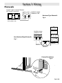
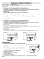
ENTRAPMENT PROTECTION:
Theinstallationofamonitoredfailsafeexternalreversingdeviceisrequiredonallmomentarycontact
electronicallyoperatedcommercialdoors.Ifsuchareversingdeviceisnotinstalled,theoperatorwill
reverttoaconstantcontactcontrolswitchforoperation(Closingonly).
TheReversingDevicescurrentlyULApprovedare:
• MillerEdge®MEandMTseriesmonitorededgesensorsusedincombinationwithTimer-CloseModule(TCM)expansionboard.P/N
OPABTCGX.
• MillerEdge®MEandMTseriesmonitorededgesensorsusedincombinationwithMillerEdgeInterfaceModuleOPAKMEIGX.S.
(DirectconnectthroughSTBinputs.)
• MillerEdge®Wireless(MEL)monitorededgesensorOPAKMMWE2.S.(DirectconnectthroughSTBinputs.)
• ASOSentirGFSeriesMonitoredSensingEdgesusedincombinationwithEdgeExpansionModule(ESM)expansionboard.P/NOPABESX.S
• ResidentialSafe-T-Beam®MonitoredPhotocells-P/N37220R(GSTB-BX)and38176R.S(includesextensionbrackets).
• SeriesIICommercialSafe-T-Beam®MonitoredPhotocells-P/NOPAKPE2.SandOPAKPEN4GX.S(NEMA4).
• MonitoredRetro-ReectivePhotoeye-P/NOPGAKRPEN4X.S
• MonitoredMillerEdgeLightCurtain-P/NOPAKMLC3.S&OPAKMLC6.S
MonitoredSensingEdgesareavailableinanydoorwidth.
NOTE: DO NOT use take up reels in conjunction with the Monitored Sensing Edge system. Use Coil Cords Only.
IMPORTANT INSTALLATION INFORMATION

Sec-2.1
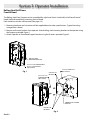
Section 2: Operator Installation
ROLLING STEEL
MOUNTING BRACKETS
5/16-18 X 3/4 CARRIAGE BOLT
& 5/16-18 FLANGE NUT
(QTY 4 EACH)
POWER HEAD SUPPORT
BRACKET
USE THIS SET
OF HOLES
5/16-18 X 1-1/4
CARRIAGE BOLT
(QTY 4 EACH)
5/16-18 FLANGE NUT
(QTY 4 EACH)
USE THIS SET
OF HOLES
Fig. 1
Fig. 2
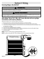
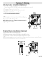
Rolling Steel/Grill Doors
Front of Hood
TheRollingSteelDoorOperatorcanbeassembledforright-hand(Hoist&Jackshaft)orleft-handFrontof
Hood(Jackshaftmodelonly)mountingFrontofHood.
Eachmodelcanalsobewallmounted(Seepage4.3).
1. Mountinghardwareandinstructionwillbesuppliedbasedondoorspecications.(Typicalmounting
arrangementsshown.)
2. Removewallmountbracketsfromoperator.Attachrollingsteelmountingbracketstotheoperatorusing
thefastenersprovided.Figure1.
3. AttachOperatortoPowerheadSupportbracketusingthefastenersprovided.Figure2.

Sec-2.2
Section 2: Operator Installation
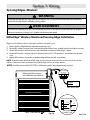
Chain Installation. Figure 3
1. Install 1 2 tooth sprocket on operator output shaft.
2. Align keyways and insert key into sprocket and output shaft keyway.Do not tighten set screw at this time.
3. Install door sprocket on door shaft. Do not tighten at this time.
4. Assemble chain using chain master link.
5. Place assembled chain over door shaft sprocket and around the 12 tooth sprocket.
6. Using the slots in the mounting bracket, adjust the operator to remove slack from the chain. Be certain
operator output shaft is parallel with the door shaft.
7. Tighten operator mounting bracket nuts.
8. Tighten sprocket set screws.
Fig. 3
17"
12"
5-1/8"
3-1/2"
8-3/4"
11"

Sec-2.3
Section 2: Operator Installation
Fig. 4
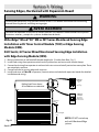
Rolling Steel/Grill Doors
Wall Mount
TheGCL-MJ&MH™RollingSteelunitcanbewallmountedwherenecessary.Fig.4.
1. Attach12toothsprockettooperatoroutputshaft.
2. Alignkeywaysandinsertkeyintosprocketandoutputshaftkeyway.Donottightensetscrewyet.
3. Attachdoorsprockettodoorshaft.Donottightenyet.
4. Assemblechainusingchainmasterlink.
5. Placeassembledchainoverdoorshaftsprocketand
6. Raiseorloweroperatortoremoveslackfromthechain.Ensureoperatoroutputshaftisparallelwithdoor
shaft.
7. Alignchainandsecureoperatortowall.
8. Tightenoperatorchainsprocketsetscrews.
9. Slideoperatorinthewallbracketmountingholesifnecessaryforne
adjustofchaintension.
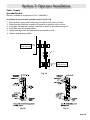
JACKSHAFT VERSION
The release
cable must
be attached
before
mounting
the unit.
RELEASE CORD
5" TO 3-3/4"
12-1/4" TO 11"
19-5/8"
(HEIGHT OF OPERATOR
15"
(TYPICAL SIDE ROOM)
13-7/8"
(OUTPUT SHAFT LENGTH)
VERTICALLY ALIGN
SPROCKETS/CHAIN
(WIDTH OF OPERATOR)
LOCK DOWN HOLES
MUST BE USED TO
ENSURE MAINTAINING
OPERATOR POSITION
LOCK DOWN HOLES
MUST BE USED TO
ENSURE MAINTAINING
OPERATOR POSITION
NOTE: Operator must be securely fastened to the wall using lock down holes.

Sec-2.4
Section 2: Operator Installation
Fig. 5B
Sectional Doors
Chain - Couple
TheWallMountOperatorcanbeassembledforrighthandmountingaboveorbelowthedoorshaft.Fig.5A.
1. Attach12toothsprockettooperatoroutputshaft.
2. Alignkeywaysandinsertkeyintosprocketandoutputshaftkeyway.Donottightensetscrewatthis
time.
3. Attachdoorsprockettodoorshaft.Donottightenatthistime.
4. Assemblechainusingchainconnectinglink.
5. Placeassembledchainoverdoorshaftsprocketandoperatorsprocket.
6. Raiseorloweroperatortoremoveslackfromthechain.
7. Becertainoperatoroutputshaftisparallelwithdoorshaft.
8. Alignchainandsecureoperatortowallormountingpad.Fig.5B.
9. Tightenoperatorsprocketsetscrews.
NOTE: The operator output shaft extends 3-7/8” on each side of the operator frame.
NOTE: If using slotted mounting holes to mount unit,
you must use at least 2 lockdown holes in opposite
corners to rmly mount unit to wall. Fig. 5B
INSTALLATION TIP:
Whilesprocketsetscrewsareloose,ifpossible,manuallyoperatedoortohelpalignchain.Aproperly
tensioneddrivechainshoulddeectnomorethan
1/2”whenthumbpressureisappliedmid-way
betweenthe2sprockets.Whilethereisnohardand
fastrulegoverningchaintension,itmustbetight
enoughtopreventclicking,poppingandjumping
theteethofthesprocket.The1/2”guidelinewill
insuresucienttension.
DOOR SHAFT
IMPORTANT: DOOR SHAFT
& OPERATOR OUTPUT
SHAFT MUST BE PARALLEL
12”-15”
CENTER
DISTANCE
LOCK DOWN HOLES
OPERATOR OUTPUT SHAFT
LOCK DOWN HOLES
NOTE: OPERATOR MUST BE
SECURELY FASTENED TO
THE WALL USING LOCK DOWN
HOLES TO ENSURE PROPER
CHAIN TENSION
Fig. 5A

Sec-2.5
Section 2: Operator Installation
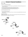
Chain - Couple
For Hollow Counterbalance Door Shafts:
1. Usenon-threadedholeindoorshaftsprocketasaguideanddrilla3/8”diameterholethroughoneside
ofthedoorshaft.Fig.6A.
2. Insertclevispinthroughsprocketandshafttoholdsprocketinposition.
3. Drillthroughoppositesideofshafttoobtainproperholealignment.Fig.6B.
4. Insertclevispinthroughbothholesandsecurewithcotterpin.Fig.6C.
For Solid Counterbalance Door Shafts:
1. Insertkeyintodoorshaftkeyway.
2. Slidesprocketintoplaceandsecurewithsetscrews.Insertclevispinthroughbothholesandsecurewith
cotterpin.Fig.6C.
Complete the Installation
Ifneeded,realignoperatorsprocketwithdoorsprocket.Ifyouhaveexcessivedoorshaftmovement,anop-
tionalchaintensionplateisavailable.Fig.7A&7B,pg4.6.
I
L
Fig. 6A
Fig. 6B
Fig. 6C

Sec-2.6
Section 2: Operator Installation
Fig. 7A
Chain - Couple
Spreader Bracket
Bracketisavailableasanoptionalkit,P/N111005.0001.S
Installation of optional chain spreader bracket: Fig 7A & 7B.
1. Placesprocket,upperplateandbearingassemblyondoorshaftasshown.
2. Placelowerplate,bearingassemblyandsprocketonoperatorshaftasshown.
3. Installdoorandoperatorsprocketsandchainassemblyasdescribedonpage4.4.
4. Installboltsandnutsthroughplates.
5. Tightenandalignchainandplateandsecureoperatortowall.
6. Tightenspreaderbracketbolts.
OPERATOR
SHAFT
DOOR
SHAFT
SPROCKET
GOES ON FIRST
SPROCKET
GOES ON LAST
PL
Fig. 7B Fig. 7C

Sec-2.7
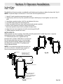
Section 2: Operator Installation
Clutch Adjustment:
TheMXOperatorshaveanadjustablefrictionclutchwhichrequiresadjustmentduringinstallation.
NOTE: The clutch is intended to provide protection for the door,
the operator and associated equipment. It is not intended for
entrapment protection. MX Operators have a motor reversing
feature that is integrated with the clutch assembly. If an
obstruction is placed in the pathway of the door during operation
the MX motor will stop and reverse when the clutch begins to slip.
Therefore, the adjustment of the clutch should be such that the
door and operator function in this manner.
To Adjust the Clutch:
1. Decreasethetensionontheclutchuntiltheoperatorwill
notliftthedoor.Turntheadjustingcastlenutcounter-
clockwisetodecreaseclutchtensionandclockwiseto
increaseclutchtension.
2. Aftercompletingstep1,begintoincreasetensionon
theclutchuntiltheoperatoriscapableofliftingthedoor
throughthecompletecyclewithoutclutchslippage.
3. Testthereversingfeatureoftheoperatorbyplacinganobstructionunderthedoorduringaclosecycle
Thedoorshouldreverseontheobstructionandreturntotheopenposition.Ifthedoordoesnotclose
butcomesdownpartwayandreverseswithoutanyobstructionsinitspath,thenincreasetheclutch
tensionuntilthedoorwillclosefully.
4. Finally,insertthecotterpinthroughthecastlenutandshaftandbendtheouterlegofthecotterpin.
NOTE: Periodically check the system for proper clutch action. If clutch starts to slip after working properly for
some time, check manual operation of door BEFORE adjusting clutch. The door may not be operating freely or
the counterbalance spring may need adjusting. Repairs and adjustments must be performed by a trained service
representative using proper tools and instructions.
To Adjust the Brake:
1. LoosentheAdjustmentBracketLockNut/Bolt.
2. SlidetheAdjustmentBracketasneededtoreachthe
desiredspringtension.Whenproperlyadjusted,the
pivotarmshouldmovewithverylittleeort.
3. Re-tightentheAdjustmentBracketLockNut/Bolt.
CLUTCH PAD
CLUTCH PLATE
CLUTCH PULLEY
WASHER
COTTER PIN
ADJUSTING NUT
SPRING
LOCK NUT & BOLT for
BRAKE ADJUSTMENT
Fig. 8
Fig. 9

Sec-2.8
Section 2: Operator Installation
Fig. 10
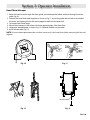
Hand Chain & Keeper
1. Routethehandchainthroughthechainguide,aroundthepocketwheelandbackthroughthechain
guide.Fig.10.
2. ConnectthehandchainendstogetherasshowninFig11.bytwistingopenthelastlinkononeendof
thechain,andslippingthelastlinkontheoppositeendontotheopenlink.
3. Twistopenlinkclosedagain.
4. Mountchainkeepertowallinlinewithchainapproximately4feetfromoor.
5. Loopchainaroundkeeperasshown.Fig.12.OptionalPadlocknotprovided.
6. Installreleasecable.Fig.13.
NOTE: To insure smooth operation,make sure there are no twist in the hand chain before connecting the link ends
together.
RELEASE CORD
Fig. 11
Fig. 12 Fig. 13

Sec-3.1
Section 3: Wiring
WARNING
• DONOTapplypowertooperatoruntilinstructedtodoso.
• Itisstronglyrecommended,andmayberequiredbylawinsomeareas,thatlinevoltagewiringbeperformed
byaqualiedelectrician.
• Besurethatelectricalpowerhasbeendisconnectedfromtheinputpowerwiresbeingconnectedtothe
operatorpriortohandlingthesewires.Anappropriatelock-out/tag-outprocedureisrecommended.
• Linevoltagewiringmustmeetalllocalbuildingcodes.
• Makesureoperatorvoltage,phaseandfrequencynameplateratingsareidenticaltothejobsitelinevoltage
ratings.
• Inputpowerwiringmustbeproperlysizedfortheoperatorsamperageratinglocatedonthenameplate.
• Toreducetheriskofelectricshock,makesurethechassisofthisunitisproperlygrounded.
!
• NEPASmettresoustensiontantquel’instructionn’estpasdonnéedelefaire.
• Ilestfortementrecommandévoiremêmeexigéparlaloidanscertainesrégions,decontacterunélectricien
qualiépourl’acheminementdulélectrique.
• Assurez-vousquel’alimentationélectriqueaétédéconnectéedescâblesd’alimentationd’entréeconnectés
àl’opérateuravantdemanipulercescâbles.Uneprocéduredeverrouillage/étiquetageappropriéeest
recommandée.
• Lecâblageausecteurdoitsatisfaireàtouslescodesdeconstructionlocaux.
• Assurez-vousquelesvaleursnominalesdelaplaquesignalétiquepourtension,phaseetfréquencede
l’opérateurcorrespondentàcellesdestensionsdel’alimentationsursite.
• Lacapacitéd’entréedoitcorrespondreàlavaleurnominaledel’ampéragedesopérateursindiquéesurla
plaquesignalétique.
• Pourréduirelerisquedechocélectrique,assurez-vousquelechâssisdel’unitéestcorrectementmisàlaterre.
AVERTISSEMENT
!
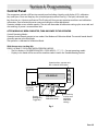
Installationofallwiringandconnections,includingPowerLimitedClass1andClass2circuits,shallbeperformedin
accordancewith,butnotlimitedto,thelatestNFPA,UL,andN.E.C.standardsandcodes.
Inaddition,allinstallationssubjecttoCanadianstandardsshallbeperformedinaccordancewiththeCanadian
ElectricalCode,Part1,withrespecttowiringmaterialtype,wiringgaugerelatedtopowercapacityrequirements,
circuitlengthandwiringmethods.
NOTE

Sec-3.2
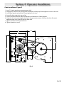
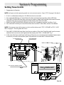
OPEN CLOSE
N-O
SAFETY
N-O
SAFETY
ODC
STB
ODC
STB
EXT
INTLK
EXT
INTLK
OPEN
CLOSE
STOP
1-BTN
STATION
KEY
SWITCH
STATION
CARD
READER
O/C
PULL
SWITCH
RELAY
GND
NOM
+ 24VDC
N/O
N/O
N/O
N/O
3-BUTTON
STATION
MONITORED SENSING EDGEINTERFACE MODULE
(OPAKMEIX.S)
RADIO
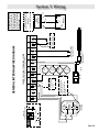
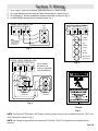
REMOVE JUMPER
WHEN INSTALLING
EXTERNAL INTERLOCK
CONTROL SIGNAL TERMINAL STRIP
MULTIPLE 3-BUTTON
STATION INSTALLATIONS
REQUIRE THE STOP
BUTTON TO BE WIRED
IN SERIES
REMOVE JUMPER
IF STOP BUTTON
IS USED
EXT
RADIO
CONNECTOR
PIGTAIL
LINE IN
POWER CONNECTIONS
L1/ L1
N/ L2
GND
120V
208/230V
LINE
(HOT)
NEUTRAL
LINE 1
LINE 2
SINGLE
PHASE
STOP GND 1-BTN
Blue
Orange
Yellow
Special Application
External Radio Terminal
0-40 VDC
250mA. Max Current
Power-Limited Class 2 Supply 0-40VDC
Non-Monitored
Sensing Device
STB
-or-
External Radio connections
are Non-Power-Limited.
All connections are to be
made within 20ft. (6.1M),
enclosed in conduit and in
the same room.
GENERAL INTERNAL WIRE DIAGRAM
Section 3: Wiring

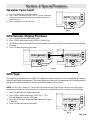
Sec-3.3
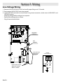
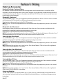
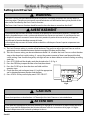
1) RemoveLINEVOLTAGEINPUTPLUGandinstallproperttingsand1/2”conduit.
2) RouteproperLINEVOLTAGEwiresintooperator.
3) LocateLINEINPUTterminalsoncircuitboard.Usingcorrectconnectors,attachwirestoLINEINPUTS,and
GROUNDterminal.
• Keeplowvoltageandlinevoltagewiresseparate.
• Routealllinevoltagewiresasshown.
• Plugallunusedconduitholes.
Line Voltage Wiring
Section 3: Wiring
.1"- &'.5"
5,.1 !-/ <B$,-
000-C.0
5)8",9
000-C.0
5)8",9
./&
5,$
./&
5,$
00"2,
+-, '(
00"2,
+-, '(
'<
-
HIGH VOLTAGE
INPUT PLUGS
LINE INPUT
TERMINALS
LINE
GROUND
ROUTE LINE VOLTAGE
WIRING IN SHADED
AREA AS SHOWN
L1/ L1
N/ L2
GND
LINE IN
POWER CONNECTIONS
120V
240V
LINE
(HOT)
NEUTRAL
LINE 1
LINE 2

Sec-3.4
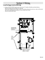
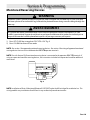
1) ConnectallLOWVOLTAGEcontrolcircuitwiresusing1/2”conduitorexibleconvolutedtubing.
• Keeplowvoltageandlinevoltagewiresseparate.
• Routealllowvoltagecontrolwiringasshown.Thisincludesallcontrolcircuitwiressuchaswallcontrols,
timersandsinglebuttoninputdevicesaswellassafetycircuitwiring.
• Plugallunusedconduitholes.
Low Voltage Control Wiring
Section 3: Wiring
.1"- &'.5"
5,.1 !-/ <B$,-
000-C.0
5)8",9
000-C.0
5)8",9
./&
5,$
./&
5,$
00"2,
+-,'(
00"2,
+-,'(
'<
-
LOW VOLTAGE
CONTROL WIRE
TERMINALS
LOW
VOLTAGE
INPUT
PLUGS
ROUTE LOW VOLTAGE
WIRING IN SHADED
AREA AS SHOWN

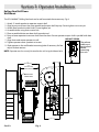
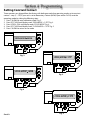
Sec-3.5
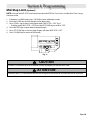
Wall Controls
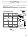
WARNING
• WallControl(s)mustbelocatedsothatthedooriswithinsightoftheuserandisfarenoughfrom
thedoor,orpositionedsuchthattheuserispreventedfromcomingincontactwiththedoorwhile
operatingcontrols.
• AttachtheWarningplacardadjacenttotheWallControl.Fig.4A.
• AttachtheCautionlabeladjacenttotheWallControl.Fig.4B.
!
AVERTISSEMENT
!
• Laoulescommandesmuralesdoiventêtresituéesdetellesortequel’utilisateurpuissevoirlaporteet
positionnéesdetellesortequel’utilisateurnepuissepasentrerencontactaveclaportelorsqu’ilsesert
descommandes.
• Fixezleposterd’avertissementàcôtédelacommandemurale.Fig.4A
• Fixerl’étiquettedemiseengarde(Attention)àcôtédelacommandemurale.Fig.4B.
Avantd’utiliserlacommandeàcontactmomentanésurleboutonFERMETURE,undispositifd’inversion
externesurveilléetelqu’unsystèmedecellulephotoélectriqueouuncommutateurdedétectiondebord
doitêtreutilisé.
Voirl’installationdesdispositifsdeprotectioncontrelecoincementen.
WARNING
BeforemomentarycontactcontrolcanbeusedontheCLOSEbutton,amonitoredexternalreversing
devicesuchasaphotocellsystemorsensingedgeswitchmustbeused.
SeeENTRAPMENTSECTIONforinstallationofentrapmentprotectiondevices.
!
AVERTISSEMENT
!
Section 3: Wiring
La page est en cours de chargement...
La page est en cours de chargement...
La page est en cours de chargement...
La page est en cours de chargement...
La page est en cours de chargement...
La page est en cours de chargement...
La page est en cours de chargement...
La page est en cours de chargement...
La page est en cours de chargement...
La page est en cours de chargement...
La page est en cours de chargement...
La page est en cours de chargement...
La page est en cours de chargement...
La page est en cours de chargement...
La page est en cours de chargement...
La page est en cours de chargement...
La page est en cours de chargement...
La page est en cours de chargement...
La page est en cours de chargement...
La page est en cours de chargement...
La page est en cours de chargement...
La page est en cours de chargement...
La page est en cours de chargement...
La page est en cours de chargement...
La page est en cours de chargement...
La page est en cours de chargement...
La page est en cours de chargement...
La page est en cours de chargement...
La page est en cours de chargement...
La page est en cours de chargement...
La page est en cours de chargement...
La page est en cours de chargement...
La page est en cours de chargement...
La page est en cours de chargement...
La page est en cours de chargement...
La page est en cours de chargement...
-
 1
1
-
 2
2
-
 3
3
-
 4
4
-
 5
5
-
 6
6
-
 7
7
-
 8
8
-
 9
9
-
 10
10
-
 11
11
-
 12
12
-
 13
13
-
 14
14
-
 15
15
-
 16
16
-
 17
17
-
 18
18
-
 19
19
-
 20
20
-
 21
21
-
 22
22
-
 23
23
-
 24
24
-
 25
25
-
 26
26
-
 27
27
-
 28
28
-
 29
29
-
 30
30
-
 31
31
-
 32
32
-
 33
33
-
 34
34
-
 35
35
-
 36
36
-
 37
37
-
 38
38
-
 39
39
-
 40
40
-
 41
41
-
 42
42
-
 43
43
-
 44
44
-
 45
45
-
 46
46
-
 47
47
-
 48
48
-
 49
49
-
 50
50
-
 51
51
-
 52
52
-
 53
53
-
 54
54
-
 55
55
-
 56
56


Genie GCL-MJ / GCL-MH Operator / Installation Manual
- Catégorie
- Porte de garage
- Taper
- Operator / Installation Manual
dans d''autres langues
- English: Genie GCL-MJ / GCL-MH
Documents connexes
-
Genie GCL-LJ Manuel utilisateur
-
-
Genie GCL-MT Manuel utilisateur
-
-
Genie GCL-J&H 1HP Guide d'installation
-
-
Genie GCL-GT Operator / Installation Manual
-
Genie GCL-T Operator / Installation Manual
-
-