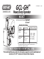
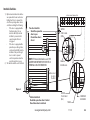
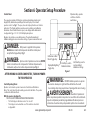
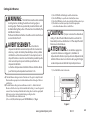
Genie GCL-GH Operator / Installation Manual
- Catégorie
- Porte de garage
- Taper
- Operator / Installation Manual

This Installation Manual provides the information required to install, troubleshoot and
maintain a GCL-GH
™
Commercial / Industrial Door Operator.
NOT FOR RESIDENTIAL USE
PROPER APPLICATION
Rolling Steel Hoist
(All Types) (F
Wall Mount)
ront of Hood or
Door Type Operator Type HP/Max Door Weight
Sectional Hoist
1/2HP = 1310 lbs.
(All Types) (Side/
3/4HP = 1450 lbs.
Centermount)
1HP = 1650 lbs.
3HP = 3696 lbs.
WITH EXCLUSIVE FEATURES:
MultiVolt
®
EZ Limit®
Heavy Duty Operator
GCL-GH
™
111837.502351 04-14
HOIST
*Door weights for Rolling Steel Doors are based on sprocket selection
derived from the configurator guidelines.

THIS PAGE LEFT BLANK

Table of Contents
Section 1 How to use this manual . . . . . . . . . . . . . . . . . . . . . . . . . . . . . . 1.1
Section 2 Safety Information & Instructions . . . . . . . . . . . . . . . . 2.1-2.2
Section 3 Critical Installation Information . . . . . . . . . . . . . . . . . . .3.1-3.4
Section 4 Installation . . . . . . . . . . . . . . . . . . . . . . . . . . . . . . . . . . . . . .4.1-4.6
Rolling Steel Front of Hood . . . . . . . . . . . . . . . . . . . . . . . . 4.1-4.2
Section 5 Wiring . . . . . . . . . . . . . . . . . . . . . . . . . . . . . . . . . . . . . . . . . 5.1-5.13
Safety Information/ Line Voltage Wiring . . . . . . . . . . . 5.1-5.2
Low Voltage Control Wiring .................. . . . . . . . . . 5.3
External Wire Diagram ....................... . . . . . . . . . 5.4
Wall Control ............................. . . . . . . . . . . . . . 5.5
Interlock Switches ........................ . . . . . . . . . . . . 5.6
Photocell Device Wiring . . . . . . . . . . . .......... . . . . . . . . . 5.7
Sensing Edge Switch........................ . . . . . . 5.8-5.9
External Radio (Optional)..................... . . . . . . . . 5.10
Motor Connection/ Safety Instructions ........ . . . 5.11-5.13
Section 6 Operator Setup Procedures . . . . . . . .
. . .
. . . . . . . . . . 6.1-6.10
Setting Close Direction...................... . . . . . . . . . . 6.2
Setting Braking Rate ....................... . . . . . . . . . . . 6.3
Setting Travel Limits ........................ . . . . . . . . . . 6.4
Setting Limit Overrun . . . . . . .................. . . . . . . . . . 6.5
Setting Open & Close Modes ................. . . . . . . . . . 6.6
(Optional) Transmitter Programming ......... . . . . . . . . . 6.7
(Optional) Mid-Stop Limit Setting ............ . . . . . . . . . 6.8
Resetting the MRT . . . . . . . . . . . . . . . . . . . . . . . . . . . . . . . . . . . . 6.9
Section 7 Special Operational Features. . . . . . . . . . . . . . . . . . . . . 7.1-7.2
Operator Cycle Count ........................ . . . . . . . . .7.1
GDO & Display Firmware ..................... . . . . . . . . .7.1
Operator Type ........................... . . . . . . . . . . . . .7.2
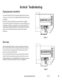
Section 8 Troubleshooting . . . . . . . . . . . . . . . . . . . . . . . . . . . . . . . . 8.1-8.5
Display Operation.......................... . . . . . . . . . . .8.1
Error Codes .......................... . . . . . . . . . . . . . 8.1-8.2
Run Codes ........................... . . . . . . . . . . . . . 8.2-8.3
LED Indicators ........................... . . . . . . . . . . . . .8.4
Safe-T-Beam® Self-Diagnostic
Troubleshooting Chart . .8.5
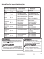
Section 9 Service & Maintenance . . . . . . . . . . . . . . . . . . . . . . . . . . . . . .9.1
Periodic Maintenance Schedule .................. . . . . . . . . .9.1
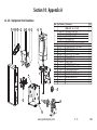
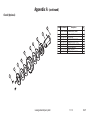
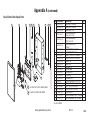
Section 10 Appendixes . . . . . . . . . . . . . . . . . . . . . . . . . . . . . . . . . 10.1-10.13
Appendix A ........................ . . . . . . . . . . . . 10.1-10.9
Operator Parts Breakdown . . . . . . . . . . . . . . . . . . 10.1-10.2
Section 11 Warranty . . . . . . . . . . . . . . . . . . . . . . . . . . . . . . . . . .
. . . . . . . 11.1
TOC
www.geniecompany.com 04-14
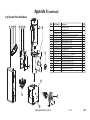
Wall Mount Kit (Chain Couple) .......... . . . . . . . . . 10.3
Hoist Shafts Parts Breakdown ........... . . . . . . . . . 10.4
Motor Options........................ . . . . . . . . . . . 10.5
Brake/Release Assemblies. . . . . . . . . . . . . . . . . . . . . . . . .10.6
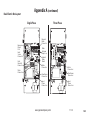
Base Electric Box Parts Breakdown ...... . . . . . . . . . 10.8
Electric Box Layout ..................... . . . . . . . . . 10.9
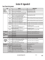
Appendix B . . . . . . . . . . . . . . . . . . . . . . . . . . . . . . . . . . . . . . . . 10.10
Screw Terminal Assignments........... . . . . . . . . . 10.10
Appendix C ........................ . . . . .
. . . . .
10.11-10.13
Run Codes.......................... . . . . . . . . . . . . 10.11
Error Codes ........................ . . . . . 10.12-10.13
Rolling Steel Wall Mount/Sectional Side Mount . . . . . . . . . 4.3
Optional Chain Couple Tension Bracket . . . . . . . . . . . . . . .
4.4
Manual Handwheel/Release Cord ............ . . . . . . . . . 4.5
Optional Clutch.......................... . . . . . . . . . . . . . 4.6
Clutch Option . . . . . . . . . . . . . . . . . . . . . . . . . . . . . . . . . . . 10.7
Monitored Reversing Devices ............... . . . . . . . . . 6.10

1.1
www.geniecompany.com 04-14
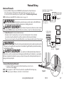
Section 1: How to use this manual
The 11 sections of this Installation Manual provide the information required to install, troubleshoot and maintain this commercial/industrial
door operator.
Section 2
Provides important defining information related to safety terminology used throughout this manual, as well as safety related instructions which
must be followed at all times while doing any steps/tasks/instructions detailed in this manual.
Section 3
Details pre-installation concerns/issues/decisions that are recommended to be considered and/or resolved prior to beginning any commercial door
operator installation.
Sections 4-6
Provides step by step installation and set-up instructions for this commercial door operator. Each section is written such that it must be
followed in a step by step order to complete a successful installation.
Sections 7-8
Details important features and troubleshooting information for typical installation and normal operations that may occur.
Sections 9-11
Provides related information on service and maintenance items, operator drawings for use in troubleshooting and service activities, along with
important warranty and returned goods policy information.
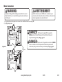
Failure to correctly perform all steps in sections 4-6 can result in serious injury or death.
WARNING
AVERTISSEMENT
Ne pas effectuer correctement toutes les étapes dans les sections 4-6 peut entraîner des
blessures graves voire la mort.

2.1
www.geniecompany.com 11-13
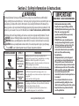
Section 2: Safety Information & Instructions
WARNING
Commercial/Industrial Sectional and Rolling Steel Doors are large, heavy objects that move with
the help of
springs under high tension and electric motors. Since moving objects, springs under tension, and electric motors can
cause injuries, your safety and the safety of others depends on you reading the information in this manual. If you
have any questions or do not understand the information presented, call your nea
rest service representative. For the
number of your local Genie® Dealer, call 800-OK-GENIE, and for Genie® Technical Service, call 800-843-4084.
In this Manual, the words Danger, Warning, and Caution are used to stress important safety information. The word:
DANGER
indicates an imminently hazardous situation which, if not avoided, will result in death or serious injury.
WARNING
indicates a potentially hazardous situation which, if not avoided, could result in death or serious injury.
CAUTION
indicates a potentially hazardous situation which, if not avoided, may result in injury or property damage.
The word NOTE is used to indicate important steps to be followed or important considerations.
IMPORTANT
READ PRIOR TO ANY DOOR OPERATION
POTENTIAL HAZARD EFFECT PREVENTION
Do Not operate unless the doorway is in sight and free of
obstructions. Keep people clear of opening while door is moving.
Do Not allow children to play with the door operator.
Do Not change operator control to momentary contact unless an
external reversing means is installed.
Do Not operate a door that jams or one that has a broken spring.
Could result in
Serious Injury
or Death
Turn off electrical power before removing operator cover.
When replacing the cover, make sure wires are not pinched or near
moving parts.
Operator must be electrically grounded.
Do Not try to remove, repair or adjust springs or anything to which
door spring parts are fastened, such as, wood block, steel bracket,
cable or any other structure or like item.
Repairs and adjustments must be made by a trained service
representative using proper tools and instructions.
HIGH SPRING TENSION
WARNING
MOVING DOOR
1. Read manual and warnings carefully.
2. Keep the door in good working condition.
Periodically lubricate all moving parts of door.
3. If door has a sensing edge, check
operations monthly. Make any necessary
repairs to keep it functional.
4. AT LEAST twice a year, manually operate
door by disconnecting it from the operator.
The Door should open and close freely. If it
does not, the door must be taken out of
service and a trained service representative
must correct the condition causing
the malfunction.
5. The Operator Motor is protected against
overheating by an internal thermal protector.
If the operator ceases to function because
motor protector has tripped, a trained service
technician may need to correct the condition
which caused the overheating. When moto
r
has cooled, thermal protector will
automatically reset and normal operation can
be resumed.
6. In case of power failure, the door can be
operated manually by pulling the release
cable to disconnect the operator drive system.
7. Keep instructions in a prominent location
near the pushbutton.
Could result in
Serious Injury
or Death
WARNING
Could result in
Serious Injury
or Death
WARNING
ELECTRICAL SHOCK

2.2
Section 2: Safety Information & Instructions
www.geniecompany.com 04-14
AVERTISSEMENT
Les portes de garage commerciales/industrielles à sections et en acier roulantes sont de gros objets lourds qui fonctionnent à l’aide de ressorts soumis à une haute tension et
de moteurs électriques. Dans la mesure où les objets en mouvement, les ressorts sous tension et les moteurs électriques peuvent entraîner des blessures, votre sécurité et celle
des autres exigent que vous preniez connaissance des informations stipulées dans ce manuel. Si vous avez des questions ou si vous ne comprenez pas les informations
ci-incluses, veuillez contacter le représentant de service le plus près. Pour obtenir le numéro du revendeur Genie® local, appelez le +1 (800)-OK-GENIE, et pour obtenir
des conseils techniques de l'usine Genie®, appelez le +1 (800)-843-4084.
Dans ce manuel, les mots Danger, Avertissement, et Attention sont utilisés pour faire ressortir d’importantes informations relatives à la sécurité. Le mot :
DANGER
signale une situation dangereuse imminente qui si elle n'est pas évitée, risque d'entraîner des blessures graves, voire mortelles.
Le terme REMARQUE est utilisé pour signaler les étapes importantes à suivre ou d’importants éléments à prendre en considération.
DANGER POTENTIEL
EFFET
PRÉVENTION
Utiliser uniquement si la porte est en vue et libre de tout obstacle. Ne laisser personne
se tenir dans l’ouverture de la porte pendant qu’elle est en mouvement.
Ne pas permettre aux enfants de jouer avec l’opérateur de la porte.
Ne pas modifier la commande de l'opérateur à contact momentané à moins qu'un moyen
d'inversion externe soit installé.
Ne pas faire fonctionner une porte qui bloque ou dont le ressort est cassé.
Pourrait entraîner
des blessures
graves voire la mort
AVERTISSEMENT
Pourrait entraîner
des blessures
graves voire la mort
CHOC ÉLECTRIQUE
TENSION ÉLEVÉE DU RESSORT
PORTE EN MOUVEMENT
ATTENTION
signale une situation potentiellement dangereuse qui, si elle n'est pas évitée, risque d'entraîner des blessures ou des dommages matériels.
AVERTISSEMENT
signale une situation potentiellement dangereuse qui, si elle n'est pas évitée, risque d'entraîner la mort ou des blessures graves.
Pourrait entraîner
des blessures
graves voire la mort
Couper le courant avant d’enlever le couvercle de l'opérateur.
Lorsque le couvercle doit être remplacé, s’assurer que les fils ne sont ni
coincés ni près des pièces mobiles.
L’opérateur doit être correctement mis à la terre.
Ne pas essayer d’enlever, réparer ni ajuster les ressorts ou toute autre pièce à laquelle le
ressort de la porte est attaché, y compris blocs de bois, supports en acier, câbles ou autres
articles semblables.
Les réparations et les réglages doivent être effectués par technicien qualifié qui se sert
d’outils appropriés et qui respecte les instructions.
AVERTISSEMENT
AVERTISSEMENT

3.1
www.geniecompany.com 04-14
Job
Site Issues to Consider/Concerns
The following list of items should be considered prior to selecting an operator for a given job site.
1-Available power supply.
2-Type of door.
3-Potential operator mounting obstructions. Items to consider include, but are not limited to: side room, room above door shaft,
room below door shaft, available mounting
surface integrity, power supply location, and convenient chain hoist and release cable positioning.
4-Size of door for appropriate
operator torque and door travel speed selection.
dustiness 5-Operator mounting environment. Items to consider include operator location and dampness,
and corrosiveness of the location.
6-Door activation needs/requirements. Examples include 3 button control stations, 1 button control stations, radio controls, pull
cords, loop detectors, photoelectric controls,
key switches, etc. See “Entrapment Protection” section below.
7-Interlock switches are required under certain conditions for doors with pass doors and door locks. See page 5.6.
8-
Accessory equipment. Examples are reversing edges and/or photocell beams (required for
doors set to operate as momentary contact,), auxiliary control relays, warning lights, etc.
Section
3:
Critical
Installation
Information
ENTRAPMENT PROTECTION
The installation of a fail safe external reversing device (such as a monitored reversing edge or photocell system, etc.) is required on all momentary contact electronically
operated commercial doors. If such a reversing device is not installed, the operator will revert to a constant contact control switch for operation (Closing only).
The Reversing Devices currently UL Approved are:
MillerEdge ME and MT series monitored edge sensors used in combination with Timer-Close Module P/N OPABTCGX.S
MillerEdge ME and MT series monitored edge sensors used in combination with MillerEdge Interface Module OPAKMEIGX.S. (Direct connect through STB inputs.)
4)
Residential Safe-T-Beam® Monitored Photocells - P/N 37220R (GSTB-BX) & 38176R.S (includes extension brackets).
5)
Series II Commercial Safe-T-Beam® Monitored Photocells - P/N OPAKPE.S and OPAKPEN4GX.S (NEMA 4).
1)
2)
6) Monitored Retro-Reflective Photoeye - P/N OPGAKRPEN4X.S
MillerEdge Wireless monitored edge sensor OPAKMMWE.S.
3)
WARNING:
DO NOT apply line voltage until instructed to do so.
AVERTISSEMENT:
NE PAS mettre sous tension tant que l'instruction n'est pas donnée de le faire.

3.2
www.geniecompany.com 04-14
Section
3: Critical Installation Information
CAUTION:
Check working condition of door before installing the operator. Door must be free from sticking and binding.
If equipped, deactivate any door locking device(s). Door repairs and adjustments, including cables and spring assemblies MUST
be made by a trained service representative using proper tools and instructions.
ATTENTION:
Vérifiez l'état de fonctionnement de la porte avant d'installer l'opérateur.
La porte doit pouvoir bouger librement et ne pas coincer. Désactivez tous les dispositifs de verrouillage de la porte (si équipés).
Les réparations et les réglages de porte, plus particulièrement pour les câbles et les ressorts DOIVENT être effectués par un
technicien qualifié qui se sert d’outils appropriés et qui respecte les instructions.
Mult
— Offers all (available) voltage combinations in both single, and 3-phase units.
EZ Limit
®
— Features patent pending electro-mechanical design that sets limits through the control panel that are maintainable even through a power outage.
New Features:
MultiVolt
®

3.3
www.geniecompany.com 04-14
Section 3: Critical Installation Information
ENTRAPMENT PROTECTION
The GCL-GH
™
.0102 ,92 tsuguA gnitrats evitca stnemeriuqer 523LU htiw ecnailpmoc ni secived tnempartne detsiL LU gniwollof eht htiw desu eb nac
UNTIL ONE OF THESE MONITORED EXTERNAL ENTRAPMENT DEVICES IS INSTALLED, THE OPERATOR WILL NOT ALLOW MOMENTARY CONTACT OPERATION IN THE CLOSE DIRECTION.
Type
Mounting
Max.
Door
Weight
(Lbs)
16GA.
Flush
Steel
16GA.
Flush
Steel
Insulated
20GA.
Ribbed
Steel
20GA.
Ribbed
Steel
Insulated
24GA.
Ribbed
Steel
24GA.
Ribbed
Steel
Insulated
Nominal
24GA.
Ribbed
Steel
Nominal
24GA.
Ribbed Steel
Insulated
Insulated
PU/FIP
Insulated
PU/FIP
1.38"
1/8" Glass
1.38"
Glass
1.38"
Insulated
PU/FIP
2"
Insulated
PU/FIP
2"
20GA.
Yes
Yes
Yes
S=Jackshaft,SideMount
C=Jackshaft,CenterMount
UL L is tedHPModel
T=Trolley
Aluminum
Door
S eries ->
Note: Total door weight, and not the square footage, is the critical factor in selecting the proper operator.
Square footage measurements are based on "square doors." (Example=16' x 16')
NOTE: Doors that require special windloading and wide doors, normally require increased strutting (reinforcement). Strutting doors can significantly increase door
weight beyond weight shown. Consult Customer Service for the impact of wind load andstrutting on square foot limits.
NOTE: "PU-FIP" stands for "polyurethane, foamed-in-place." If no notation is present, insulation is "polystyrene, layed-in-place."
Sectional Door Chart (sq. ft.)
GCL-GH™ 1/2
GCL-GH™ 3/4
GCL-GH™ 1
Yes
GCL-GH™ 3
216 216 ins. 220 220 ins. 2415 2415 ins. 2411 2411 ins. 125 150 200 200-20 5150 5200 451 452
CommercialSteelInsulated&Non-Insulated Thermospan Thermomark
Exterior
Insulated
PU/FIP
Raised
Panel
1.38"
Insulated
1/4" or 1/2"
PU/FIP
Raised
Panel
2"
Model HP
FireStar® 3” SLAT
FireStar® 3” SLAT
INSULATED
SHEET DOOR
16GA. 18GA. 20GA. 22GA. 24GA. 26GA. 18GA. 20GA. 22GA.
ALUM. STL/SST 20GA. 22GA.
270
N/A
220
355
STEEL, NON-INSULATED STEEL, INSULATED
UL
L is ted
FireStar® 2” SLATGRILLESCOUNTER DOOR
ALUM. STL/SST
126 126
Rolling Steel Door Chart (sq. ft.)
Note: Total door weight and not square footage is the critical factor in selecting the proper operator. These Sq.Ft. measurements are based on square doors, e.g. 16' x 16'.
Unbalanced Fire Shutters have a maximum square footage of 52 for 22GA. steel and 42 for 20GA. steel.
GCL-GH™ 1/2 YES
GCL-GH™ 3/4 YES
GCL-GH™ 1 YES
126 126
N/A N/A
16GA. 18GA. 20GA. 22GA.
128 144 166
20GA. 22GA. 26GA.
576
GCL-GH™ 3 YES
N/A N/A
TSC 1310 300 256 410 280 520 400 320 320 256 430 430 350 450 430 400 320
TSC 1450 340 256 450 320 540 410 320 320 256 450 450 400 480 460 400 350
TSC 1650 390 290 510 380 580 410 320 320 256 480 480 420 510 490 400 400
SC 3696 700 500 700 560 770 600 320 320 256 480 900 680 530 680 400 400
250 277 277 333 360 360 194 194 222
283 350 350 442 494 N/A 232 232 283
318 420 420 548 636 N/A 244 244 303
962 1035 1152 1152 1152 N/A 728 728 986
360 280 210
490 350 N/A
580 380 320
982 982 576
N/A
272
120 128 256
N/A N/A N/A
160 180 N/A
N/A N/A N/A
176 188 246
576
300 324 N/A
342 390 576
Miller Edge ME & MT series monitored edge sensors used in
combination with OPABTCGX.S Timer-Close Module or MillerEdge
Interface Module OPAKMEIGX.S. Miller Edge Wireless monitored edge sensor OPAKMMWE.S
ANY WIDTH
Residential Safe-T-Beams® P/N 37220R (GSTB-BX) and 38176R.S (includes ext. brkt’s)
Commercial Photoeye Kit P/N OPAKPE.S and OPAKPEN4GX.S (NEMA 4)
LISTED DEVICES
ALLOWABLE DOOR WIDTH
30 FEET
35 FEET
Monitored Retro-Refective Photoeye Kit P/N OPGAKRPEN4X.S

3.4
www.geniecompany.com 04-14
IMPORTANT
INSTALLATION INSTRUCTIONS
WARNING-
To reduce the risk of severe
injury or death:
READ AND FOLLOW ALL INSTALLATION INSTRUCTIONS.
Install only on a properly operating and balanced door. A door that is
operating improperly could cause severe injury. Have qualified service
personnel make repairs to cables, spring assemblies and other
hardware before installing the operator.
Remove all pull ropes and remove, or make inoperative, all locks
(unless mechanically and/or electronically interlocked to the power
unit) that are connected to the door before installing the operator.
Install the door operator at least 8 feet above the floor if the operator
has exposed moving parts.
Do not connect the door operator to the power source until
instructed to do so.
Locate the control station: (a) within sight of the door, (b) a minimum
of 5 feet above the floor so that small children cannot reach it, and
(c) away from all moving parts of the door.
Install the Entrapment Warning Placard next to the control station
and in a prominent location.
For products having a manual release, instruct the end user on the
operation of the manual release.
IMPORTANT
INSTRUCTIONS D’INSTALLATION
AVERTISSEMENT-
Pour réduire les risques de
blessures graves ou de mort :
1)
LIRE ET RESPECTER TOUTES LES INSTRUCTIONS D'INSTALLATION.
2)
Installez uniquement sur une porte fonctionnant correctement et bien
équilibrée. Une porte qui fonctionne mal peut provoquer des blessures
graves. Demandez à un technicien qualifié d'effectuer les réparations
des câbles, des ressorts et de toute autre quincaillerie avant de
procéder à l'installation de l'opérateur.
Retirez toutes les cordes de traction ainsi que tous les verrous ou
rendez-les inopérants (à moins qu'ils ne soient mécaniquement et/ou
électroniquement interverrouillés à l'unité motrices) qui sont connectés
à la porte avant de procéderà l'installation de l'opérateur.
Installez l'opérateur de la porte à 2,4 m minimum au-dessus du sol
lorsque des pièces mobiles de l'opérateur sont exposées.
Ne pas raccorder l'opérateur de la porte à la source d’alimentation
avant que l'instruction ne soit donnée de le faire.
Installez la station de commande : (a) en vue de la porte, (b) à 1,5 m
minimum au-dessus du sol pour que les jeunes enfants ne puissent
pas l'atteindre, et (c) à l'écart de toutes les pièces mobiles de la porte.
Installez le poster d'avertissement de pincement à côté de la station de
commande à un endroit bien en vue.
Pour les produits ayant un déclenchement manuel, indiquez à l'utilisateur
comment déclencher manuellement.
3)
4)
5)
6)
7)
8)
1)
2)
3)
4)
5)
6)
7)
8)
Section 3: Critical Installation Information

4.1
www.geniecompany.com 11-13
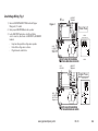
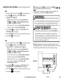
Section 4: Installation
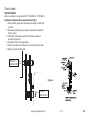
Rolling Steel
The Rolling Steel Door Operator can be assembled for right-hand or left-
hand
Front of Hood
mounting .dooH fo tnorF
Each model can also be wall mounted (See page 4.3).
1) Mount the powerhead to the headplate mounting bracket using
fasteners provided.
(Typical mounting arrangements shown in Figures 1 and 2.)
Figure 1
(1/2, 3/4 & 1 HP Operator)
Figure 2
(3 HP Operator)
3/8-16 HEX NUT W/LOCK WASHER
(QTY 4)
3/8 FLAT WASHER
(QTY 4)
3/8-16 X 1-1/2 BOLT
(QTY 4)
1/2-13 HEX NUT
(QTY 4)
1/2 LOCK WASHER
(QTY 4)
1/2 FLAT WASHER
(QTY 4)
1/2-13 X 2-1/2 BOLT
(QTY 4)
USE THE SET OF HOLES
CLOSEST TO THE BEND

4.2
www.geniecompany.com 11-13
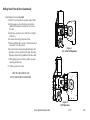
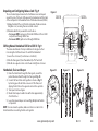
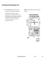
Rolling Steel Front of Hood (continued)
Attach Operator to Door: Fig. 3 & 4.
1) Attach 12 tooth sprocket to operator output shaft.
2) Align keyways and insert key into sprocket and
output shaft keyway. Do not tighten set screw at
this time.
3) Attach door sprocket to door shaft. Do not tighten
at this time.
4) Assemble chain using chain master link.
5) Place assembled chain over door shaft sprocket and
around the 12 tooth sprocket.
6) Using the slots in the mounting bracket, adjust the
Operator to remove slack from the chain. Be certain
Operator output shaft is parallel with the door shaft.
7) While applying tension to chain, tighten operator
mounting bracket nuts.
8) Tighten sprocket set screws.
REFER TO SHOP DRAWINGS FOR
SPECIFIC DIMENSIONING INFORMATION.
Figure
3
(1/2, 3/4 & 1 HP Operator)
Figure
4
(3 HP Operator)

4.3
www.geniecompany.com 11-13
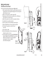
Rolling Steel/Sectional
Wall Mount/Side Mount
4-3/4”
(1/2, 3/4, 1HP)
5-1/2”
(1/2, 3/4, 1HP)
Figure 6
EDGE OF
LOCK DOWN
HOLES
OPENING
Figure 7
.deriuqer nehw detnuom llaw eb nac tinu tsioH ehT Fig. 5, 6 & 7.
4 eht gnisu )lanoitpo( rotarepo ot tekcarb tnuom llaw lanoitpo hcattA )1
mounting bolts and nuts supplied. Fully tighten. Position the operator
with the bracket as shown.
2) Attach 12 tooth sprocket to operator output shaft.
3) Align keyways and insert key into sprocket and door shaft keyway.
Do not tighten set screw at this time.
4) Attach door sprocket to door shaft. Do not tighten at this time.
5) Assemble chain using chain master link.
6) Position operator near door shaft with sprockets aligned.
7) Place assembled chain over door and operator sprockets.
8) Lift or lower the operator as needed to tension
drive chain.
9) Secure operator to wall.
10) Check
11) Lock the operator in place using the LOCK DOWN HOLES
indicated in Fig. 5. These MUST BE USED to prevent any
shifting of the operator due to the torque applied
during operation. (These are in addition
to the slotted mounting holes.)
vertical alignment of the drive chain/sprockets
and tighten sprocket set screws.
Figure 5
Optional Bracket
9-1/16”
(3 HP)
3-1/2”
(3 HP)
5-1/2”
(1/2, 3/4, 1HP)
9-1/16”
(3 HP)
4-3/4”
(1/2, 3/4, 1HP)
3-1/2”
(3 HP)

Bracket is available as an optional kit, P/N 111005.0001.S & 111005.0002.S
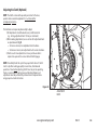
Installation of optional chain spreader bracket: Fig 8.
1) Place sprocket, upper plate and bearing assembly on door shaft
as shown.
2) Place lower plate, bearing assembly and sprocket on operator
shaft as shown.
3) Install door and operator sprockets and chain assembly as
described on page 4.3.
4) Install bolts and nuts through plates.
5) Tighten and align chain and plate and secure operator to wall.
6) Tighten spreader bracket bolts.
Tension Bracket
OPERATOR
SHAFT
DOOR
SHAFT
SPROCKET
GOES ON FIRST
SPROCKET
GOES ON LAST
Figure 8
www.geniecompany.com
4.4
11-13
Chain Couple

4.5
www.geniecompany.com 06-12
Figure 10
1) Route the hand chain through the chain guide, around the
pocket wheel and back through the chain guide. Fig. 10.
2) Connect the hand chain ends together as shown in Fig. 11.
by twisting open the last link on one end of the chain, and
slipping the last link on the opposite end onto the open link.
3) Twist open link closed again.
4) Mount chain keeper to wall in line with chain approximately
4 feet from floor.
5) Loop chain around keeper as shown. Fig. 12. Optional Padlock
not provided.
Handwheel, Chain and Keeper
NOTE: To insure smooth operation, make sure there is no twist in the
hand chain before connecting the link ends together.
Figure 11 Figure 12
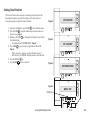
Shifting Manual Handwheel SIDE A to SIDE B: Fig. 9
The release mechanism is factory installed and is designed so that
it can be right or left-hand mount. To switch the handwheel:
1) Loosen the set screws (1) and remove set collar (2).
2) Slide the chain guard (3) and handwheel (4) off of hoist shaft.
3) Slide all onto opposite side in order shown and tighten set screws.
Figure 9
2
1
3
4
Unpacking and Configuring Release Cord: Fig. 9
The cord comes shipped connected to the Release Lever and looped
around the end of the hoist shaft opposite the handwheel, with the bulk
of the cord taped to the handwheel side of the brake enclosure (SIDE A).
1) Untape the bulk of the cord from the side panel of brake enclosure.
Straighten cord , ensuring there are no kinks or knots.
2)
Determine which side you want the cord to be on.
— For use on SIDE A, unloop cord from the SIDE B end of hoist shaft
and pull it out through SIDE A hole.
— For use on SIDE B, pull cord out through SIDE B hole.
SIDE ASIDE B

4.6
www.geniecompany.com 06-12
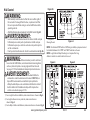
Adjusting the Clutch (Optional)
NOTE: The clutch is intended to provide protection for the door,
operator and associated equipment. It is not intended for
entrapment protection.
The clutch does not require any disassembly to adjust.
1) All adjustments should be made in very small increments
(e.g. turning adjustment bolts 1/4 turn per increment).
2) When making adjustments, be sure to turn all 3 adjustment bolts
an equal amount. Fig 13.
— To increase tension, turn adjustment bolts clockwise.
— To decrease tension, turn adjustment bolts counter-clockwise.
3) Clutch needs to be adjusted to a tension just above what is
required to open and close door without clutch slippage.
NOTE: Periodically check the system for proper clutch action. If clutch
starts to slip after working properly for some time, check manual
operation of door before adjusting clutch. Door may not be operating
freely or counter-balance spring may need adjusting. Repairs and
adjustments must be performed by a trained service representative
using proper tools and instructions.
ADJUSTMENT
BOLTS
Figure 13

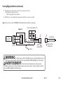
5.1
Section 5: Wiring
www.geniecompany.com 04-14
WARNING
• DO NOT apply power to operator until instructed to do so.
•
It is strongly recommended, and may be required by law
in some areas, that line voltage wiring be performed by
a qualified electrician.
• Be sure that electrical power has been disconnected from
the input power wires being connected to the operator
prior to handling these wires. An appropriate lock-out/
tag-out procedure is recommended.
•
Line voltage wiring must meet all local building codes.
•
Make sure operator voltage, phase and frequency nameplate
ratings are identical to the job site line voltage ratings.
•
Input power wiring must be properly sized for the operators
amperage rating located on the nameplate.
•
To reduce the risk of electric shock, make sure the chassis of
this unit is properly grounded.
AVERTISSEMENT
• NE PAS mettre sous tension tant que l'instruction n'est
pas donnée de le faire.
•
Il est fortement recommandé voire même exigé par la loi dans
certaines régions, de contacter un électricien qualifié pour
l'acheminement du fil électrique.
• Assurez-vous que l'alimentation électrique a été déconnectée
des câbles d'alimentation d'entrée connectés à l'opérateur
avant de manipuler ces câbles. Une procédure de verrouillage/
étiquetage appropriée est recommandée.
•
Le câblage au secteur doit satisfaire à tous les codes de
construction locaux.
•
Assurez-vous que les valeurs nominales de la plaque
signalétique pour tension, phase et fréquence de l'opérateur
correspondent à celles des tensions de l'alimentation sur site.
•
La capacité d'entrée doit correspondre à la valeur nominale de
l'ampérage des opérateurs indiquée sur la plaque signalétique.
•
Pour réduire le risque de choc électrique, assurez-vous que le
châssis de l'unité est correctement mis à la terre.

5.2
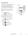
www.geniecompany.com
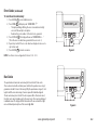
1) Remove LINE VOLTAGE INPUT PLUG and install proper
fittings and 1/2”conduit.
2) Route proper LINE VOLTAGE wires into operator.
3) Locate LINE INPUT terminals on circuit board. Using
correct connectors, attach wires to LINE INPUTS, and GROUND
terminal.
•
Keep low voltage and line voltage wires separate.
• Route all line voltage wires as shown.
• Plug all unused conduit holes.
P
HIGH
VOLTAGE
INPUT PLUGS
(Right & Left)
ROUTE HIGH VOLTAGE WIRING
IN THE SHADED AREA AS SHOWN
LINE INPUT
TERMINALS
LINE
GROUND
LINE INPUT
TERMINALS
LINE
GROUND
ROUTE HIGH VOLTAGE WIRING
IN THE SHADED AREA AS SHOWN
N/ L2L1/ L1
GND
LINE IN
POWER CONNECTIONS
LINE IN
POWER CONNECTIONS
LINE
(HOT)
NEUTRAL
LINE 1
LINE 2
GND
LINE 1
Three Phase
Single Phase
115V
208V
230V
HIGH
VOLTAGE
INPUT PLUGS
(Right & Left)
Figure 1
Line Voltage Wiring Fig. 1
04-14
L1 L2 L3
LINE 2 LINE 3

5.3
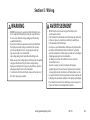
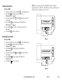
www.geniecompany.com
1) Connect all LOW VOLTAGE control circuit wires to this side
of unit using 1/2” conduit or flexible convoluted tubing.
• Keep low voltage and line voltage wires separate.
• Route all low voltage control wiring as shown. This includes
all control circuit wires such as wall controls, timers and single
button input devices as well as radio control and safety
circuit wiring. See Figs 2 through 13 in this section.
• Plug all unused conduit holes.
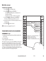
Low Voltage Control Wiring (general) Fig. 2
ROUTE LOW VOLTAGE WIRING
IN THE SHADED AREA AS SHOWN
LOW
VOLTAGE
INPUT
PLUGS
(Left &
Right)
LOW VOLTAGE
CONTROL WIRE
TERMINALS
Optional
Accessory
Modules
Figure 2
NOTE: For a detailed description of control wire terminals see
Appendix B.
06-12

5.4
www.geniecompany.com 04-14
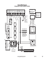
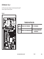
External Wire Diagram
See Appendix B for detailed description of terminals.
1-BTN
STATION
KEY
SWITCH
STATION
CARD
READER
O/C
PULL
SWITCH
N/O
N/O
N/O
N/O
REMOVE
JUMPER
WHEN
INSTALLING
EXTERNAL
INTERLOCK
MULTIPLE
3-BUTTON
STATION
INSTALLATIONS
REQUIRE THE
STOP BUTTON
TO BE WIRED
IN SERIES.
See Fig. 5, pg 5.5
*
EXT
INTLK
EXT
INTLK
N-O
REVERSE
N-O
REVERSE
ODC
STB
ODC
STB
1-BTNGNDSTOPCLOSEOPEN
EXT RADIO CONNECTOR
SENSING EDGE SWITCH
(DO NOT CONNECT
2-WIRE MONITORED
SENSING EDGE SWITCH
TO THESE INPUTS)
THRU-BEAM PHOTOCELLS
+
-
+
-
PWR
20-40 VDC @ 250mA
MAX CURRENT
RELAY
GND
NOM
+ 24VDC
RADIO
SERIES II SAFE-T-BEAM
®
(STB)
(
*
CONNECT STB WIRES
TO EITHER TERMINAL)
*
OPEN
CLOSE
STOP
REMOVE
JUMPER
IF STOP
BUTTON
IS USED
3-BUTTON
STATION
*
BLUE
ORANGE
YELLOW
Located inside
Electrical Box
2-WIRE MONITORED SENSING EDGE SWITCH
INTERFACE
MODULE
La page est en cours de chargement...
La page est en cours de chargement...
La page est en cours de chargement...
La page est en cours de chargement...
La page est en cours de chargement...
La page est en cours de chargement...
La page est en cours de chargement...
La page est en cours de chargement...
La page est en cours de chargement...
La page est en cours de chargement...
La page est en cours de chargement...
La page est en cours de chargement...
La page est en cours de chargement...
La page est en cours de chargement...
La page est en cours de chargement...
La page est en cours de chargement...
La page est en cours de chargement...
La page est en cours de chargement...
La page est en cours de chargement...
La page est en cours de chargement...
La page est en cours de chargement...
La page est en cours de chargement...
La page est en cours de chargement...
La page est en cours de chargement...
La page est en cours de chargement...
La page est en cours de chargement...
La page est en cours de chargement...
La page est en cours de chargement...
La page est en cours de chargement...
La page est en cours de chargement...
La page est en cours de chargement...
La page est en cours de chargement...
La page est en cours de chargement...
La page est en cours de chargement...
La page est en cours de chargement...
La page est en cours de chargement...
La page est en cours de chargement...
La page est en cours de chargement...
La page est en cours de chargement...
La page est en cours de chargement...
La page est en cours de chargement...
La page est en cours de chargement...
La page est en cours de chargement...
La page est en cours de chargement...
-
 1
1
-
 2
2
-
 3
3
-
 4
4
-
 5
5
-
 6
6
-
 7
7
-
 8
8
-
 9
9
-
 10
10
-
 11
11
-
 12
12
-
 13
13
-
 14
14
-
 15
15
-
 16
16
-
 17
17
-
 18
18
-
 19
19
-
 20
20
-
 21
21
-
 22
22
-
 23
23
-
 24
24
-
 25
25
-
 26
26
-
 27
27
-
 28
28
-
 29
29
-
 30
30
-
 31
31
-
 32
32
-
 33
33
-
 34
34
-
 35
35
-
 36
36
-
 37
37
-
 38
38
-
 39
39
-
 40
40
-
 41
41
-
 42
42
-
 43
43
-
 44
44
-
 45
45
-
 46
46
-
 47
47
-
 48
48
-
 49
49
-
 50
50
-
 51
51
-
 52
52
-
 53
53
-
 54
54
-
 55
55
-
 56
56
-
 57
57
-
 58
58
-
 59
59
-
 60
60
-
 61
61
-
 62
62
-
 63
63
-
 64
64


Genie GCL-GH Operator / Installation Manual
- Catégorie
- Porte de garage
- Taper
- Operator / Installation Manual
dans d''autres langues
- English: Genie GCL-GH
Documents connexes
-
Genie GCL-J&H 1HP Guide d'installation
-
Genie GCL-T Operator / Installation Manual
-
Genie GCL-GCX Operator / Installation Manual
-
Genie GCL-GT Operator / Installation Manual
-
-
-
-
-
-