Genie GCL Fire Door Operator / Installation Manual
- Catégorie
- Porte de garage
- Taper
- Operator / Installation Manual

03/2018112606.503918
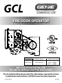
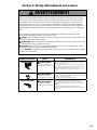
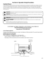
This Installation Manual provides the information required to install,
troubleshoot and maintain a OPGSX Series Fire Door Operator.
FIRE DOOR OPERATOR
NOT FOR RESIDENTIAL USE
For use on Rolling Steel Fire Doors Only
GCL
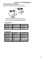
PROPER APPLICATIONS:
Door Type(s) Operator Type(s) HP/MAX. Door Weight
Rolling Steel Hoist Model Only 1/2HP = 998lbs.
Fire Door Only FOH mount only 3/4HP = 1220lbs.
1HP = 1440lbs.

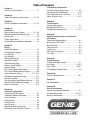
Table of Contents
Section 1:
How to use this manual ........................................1.1
Section 2:
Safety Information & Instructions ..............2.1-2.2
Section 3:
Critical Installation Information ..................3.1-3.3
Section 4:
Installation:
Rolling Steel Front of Hood ..........................4.1-4.2
Manual Handwheel/Release Cord .................... 4.3
Fusible Link ................................................................ 4.4
Clutch Adjustment ................................................. 4.5
Auxiliary Board Installation (optional) ............. 4.5
Section 5:
Wiring:
Safety Information .................................................. 5.1
External Wire Diagram ...........................................5.2
Line Voltage .............................................................. 5.3
Low Voltage .............................................................. 5.4
Wall Control Wiring .................................................5.5
Interlock Switches .................................................. 5.6
Wired Sensing Edge............................................... 5.7
Wireless Sensing Edge .......................................... 5.8
External Radio ........................................................... 5.9
FDO Control Board Information .........................5.9
FDO Control Board Wiring Diagram ...............5.10
Smoke Detector Wiring .............................5.11-5.12
Notication Appliance Wiring...........................5.13
Remote Test Plate ..................................................5.13
Fire Alarm Relay Input/Battery Wiring ...........5.14
Alarm/Trouble Indication Outputs ..................5.15
Motor Connection ................................................. 5.15
Section 6:
Operator Conguration:
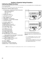
Control Panel Information .................................... 6.1
Calibration Mode Information ............................6.2
Close Direction ......................................................... 6.3
Braking Rate .............................................................. 6.4
Setting Limits ........................................................... 6.5
Limit Overrun ........................................................... 6.6
Monitored Reversing Devices .............................6.7
Momentary and Constant Contact .................. 6.8
FDO Module Conguration:
Fire Alarm Delay/Safety Timer ........................... 6.9
Obstruction Cycles/Behavior ............................6.10
Auto Open/Alarm Loss of Power .....................6.11
Alarm at Down Limit ............................................6.12
Section 7:
Test Procedures:
General Information ............................................... 7.1
Mechanical Drop Test ............................................. 7.2
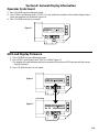
Standard & Automatic Test ...........................7.3-7.4
Section 8:
Optional Setup Procedures and General
Information:
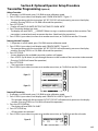
Transmitter Programming .................................... 8.1
Mid-Stop -DO NOT USE ......................................... 8.2
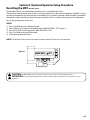
Max Run Timer .......................................................... 8.3
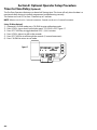
Timer to Close ...........................................................8.4
Cycle Count................................................................8.4
GDO Version/Firmware ..........................................8.5
GDO Type ................................................................... 8.5
Section 9:
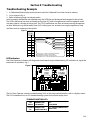
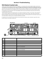
Troubleshooting:
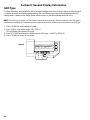
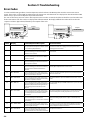
Troubleshooting Example .................................... 9.1
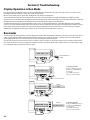
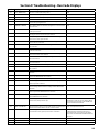
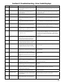
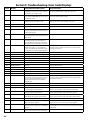
Run Codes ...........................................................9.2-9.3
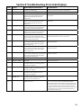
Error Codes ......................................................... 9.4.9.7
FDO Module Trouble Codes ................................9.8
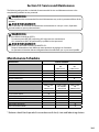
Section 10:
Service & Maintenance ....................................... 10.1
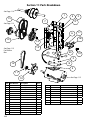
Section 11:
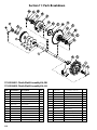
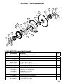
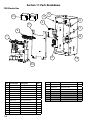
Parts Breakdown: ........................................ 11.1-11.3
Section 12:
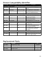
General Information:
Device Compatibility Identier ........................12.1
Test Recording Sheet .................................12.2-12.3
Warranty Information ..........................................12.4

1.1
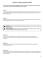
Section 1: How to use this manual
Section 2
Provides important dening information related to safety terminology used throughout this manual, as well
as safety related instructions which must be followed at all times while doing any steps/tasks/instructions
detailed in this manual.
The 12 sections of this Installation Manual provide the information required to install, troubleshoot
and maintain a Fire Door Commercial/Industrial door operator.
Section 3
Details pre-installation concerns/issues/decisions that are recommended to be considered and/or resolved
prior to beginning any commercial door operator installation.
Sections 4-6
Provides step by step installation and set-up instructions for the re door commercial operator.
Each section is written such that it must be followed in a step by step order to complete a successful
installation.
Section 7-8
Details important test features and troubleshooting information for typical installation and normal
operations that may occur.
Sections 9-12
Provides related information on troubleshooting, service and maintenance items, operator drawings for use
in troubleshooting and service activities, test recording, along with important warranty and returned goods
policy information.
WARNING: Failure to correctly perform all steps in sections 4-6 can result in serious
injury or death.
AVERTISSEMENT: Ne pas eectuer correctement toutes les étapes dans les sections
4-6 peut entraîner des blessures graves voire la mort.
!
!

2.1
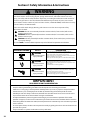
Section 2: Safety Information & Instructions
WARNING
!
Overhead Doors are large, heavy objects that move with the help of springs under high tension
and electric motors. Since moving objects, springs under tension, and electric motors can cause
injury, your safety and the safety of others depend on you reading the information in this manual. If
you have any questions or do not understand the information presented, call your nearest service
representative. For the number of your local Genie® Dealer, call 800-OK-GENIE, and for Genie® Factory
Technical Advice, call 800-843-4084.
In this manual the words Danger, Warning, and Caution are used to stress important safety
information. The word:
DANGER indicates an imminently hazardous situation which, if not avoided, will result in
death or serious injury.
WARNING indicates a potentially hazardous situation which, if not avoided, could result in
death or serious injury.
CAUTION indicates potentially hazardous situation which, if not avoided, may result in injury
or property damage.
The word NOTE, is used to indicate important steps to be followed or important considerations.
!
!
!
POTENTIAL HAZARD EFFECT PREVENTION
MOVING DOOR
WARNING
Could result in Serious
Injury of Death
Do Not operate unless the doorway is in sight and free of
obstructions. Keep people clear of opening while door is moving.
Do Not allow children to play with the door operator.
Do Not change operator control to momentary contact unless and
external reversing means is installed.
Do Not operate a door that jambs or one that has a broken spring.
ELECTRICAL SHOCK
WARNING
Could cause Serious
Injury or Death
Turn o electrical poser before removing operator cover.
When replacing the cover, make sure wires are not pinched or near
moving parts.
Operator must be electrically grounded.
HIGH SPRING TENSION
WARNING
Could cause Serious
Injury or Death
Do Not try to remove, repair or adjust springs or anything to which
door spring parts are fastened, such as wood block, steel bracket,
cable or any other structure or like item.
Repairs and adjustments must be made by trained service
representative using proper tools and instructions.
!
!
!
IMPORTANT
READ PRIOR TO ANY DOOR OPERATION
1. Read manual and warnings carefully.
2. Keep the door in good working condition. Periodically lubricate all moving parts of door.
3. If door has a sensing edge, check operations monthly. Make any necessary repairs to keep it functional.
4. AT LEAST twice a year, manually operate the door by disconnecting it from the operator. The Door
should open and close freely. If it does not, the door must be taken out of service and a trained service
representative must correct the condition causing the malfunction.
5. The Operator Motor is protected against overheating by an internal thermal protector. If the motor
protector is tripped, a trained service technical may be needed to correct the condition which caused the
overheating. When the motor has cooled, thermal protector will automatically reset and normal operation
can be resumed.
6. In case of power failure, the door can be operated manually by pulling the release cable to disconnect the
operator drive system.
7. Keep instructions in a prominent location near the pushbutton.

2.2
Les portes basculantes sont de gros objets lourds qui fonctionnent à l’aide de ressorts soumis à une
haute tension et de moteurs électriques. Dans la mesure où les objets en mouvement, les ressorts
sous tension et les moteurs électriques peuvent entraîner des blessures, votre sécurité et celle des
autres exigent que vous preniez connaissance des informations stipulées dans ce manuel. Si vous
avez des questions ou si vous ne comprenez pas les informations ci-incluses, veuillez contacter le
représentant de service le plus près. Pour obtenir le numéro du revendeur Genie® local, appelez le +1
(800)-OK-GENIE, et pour obtenir des conseils techniques de l’usine Genie®, appelez le +1 (800)-843-
4084.
Dans ce manuel, les mots Danger, Avertissement, et Attention sont utilisés pour faire ressortir
d’importantes informations relatives à la sécurité. Le mot :
DANGER signale une situation dangereuse imminente qui si elle n’est pas évitée, risque d’entraîner
des blessures graves, voire mortelles.
AVERTISSEMENT signale une situation potentiellement dangereuse qui, si elle n’est pas évitée, risque
d’entraîner la mort ou des blessures graves.
ATTENTION signale une situation potentiellement dangereuse qui, si elle n’est pas évitée, risque
d’entraîner des blessures ou des dommages matériels.
Le terme REMARQUE est utilisé pour signaler les étapes importantes à suivre ou d’importants éléments
à prendre en considération.
AVERTISSEMENT
!
!
!
!
DANGER POTENTIEL EFFET PRÉVENTION
PORTE EN MOUVEMENT
AVERTISSEMENT
Pourrait entraîner des
blessures graves voire la mort
Utiliser uniquement si la porte est en vue et libre de tout obstacle.
Ne laisser personne se tenir dans l’ouverture de la porte pendant
qu’elle est en mouvement.
Ne pas permettre aux enfants de jouer avec l’opérateur de la porte.
Ne pas modier la commande de l’opérateur à contact momentané
à moins qu’un moyen d’inversion externe soit installé.
Ne pas faire fonctionner une porte qui bloque ou dont le ressort
est cassé.
CHOC ÉLECTRIQUE
AVERTISSEMENT
Pourrait entraîner des
blessures graves voire la mort
Couper le courant avant d’enlever le couvercle de l’opérateur.
Lorsque le couvercle doit être remplacé, s’assurer que les ls ne sont
ni coincés ni près des pièces mobiles.
L’opérateur doit être correctement mis à la terre.
TENSION ÉLEVÉE RESSORT
AVERTISSEMENT
Pourrait entraîner des
blessures graves voire la mort
Ne pas essayer d’enlever, réparer ni ajuster les ressorts ou
toute autre pièce à laquelle le ressort de la porte est attaché, y
compris blocs de bois, supports en acier, câbles ou autres articles
semblables.
Les réparations et les réglages doivent être eectués par
technicien qualié qui se sert d’outils appropriés et qui respecte les
instructions.
!
!
!
Section 2: Safety Information & Instructions

3.1
Section 3: Critical Installation Information
Job Site Issues to Consider/Concerns
The following list of items should be considered prior to selecting an operator for a given job
site.
1. Available power supply.
2. Type of door.
3. Potential operator mounting obstructions. Items to consider include, but are not limited to: side
room, room above door shaft, room below door shaft, available mounting surface integrity,
power supply location, and convenient chain hoist and release cable positioning.
4. Size of door for appropriate operator torque and door travel speed selection.
5. Operator mounting environment. Items to consider include operator location, dampness of
location, dustiness of the location and corrosiveness of the location.
6. Door activation needs/requirements. Examples include 3 button control stations, 1 button control
stations, radio controls, pull cords, loop detectors, photoelectric controls, key switches, etc. See
“Entrapment Protection” section below.
7. Interlock switches are required under certain conditions for doors with pass doors and door locks.
See Section 5.6.
8. Accessory equipment. Examples include reversing edges which are required for doors set to
operate as momentary contact, auxiliary control relays, warning lights, etc. See “Entrapment
Protection” section below.
WARNING: DO NOT apply line voltage until instructed to do so.
AVERTISSEMENT: NE PAS mettre sous tension tant que
l’instruction n’est pas donnée de le faire.
!
!
ENTRAPMENT PROTECTION
The installation of a fail safe external reversing device (such as a monitored reversing edge.) is
required on all momentary contact electronically operated commercial doors. If such a reversing
device is not installed, the operator will revert to a constant contact control switch for operation
(Closing only).
The Reversing Devices currently UL Approved are:
1). MillerEdge ME and MT series monitored edge sensors used in combination with Timer-Close
Module P/N OPABTCX.S
2). MillerEdge ME and MT series monitored edge sensors used in combination with MillerEdge
Interface Module OPAKMEIX.S. (Direct connect through STB inputs.)
3). MillerEdge Wireless monitored edge sensor OPAKMMWE.S.
These Monitored Sensing Edges are available in any door width.
NOTE: DO NOT use take up reels in conjunction with the Monitored Sensing Edge system. Use Coil Cords
Only.

3.2
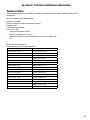
The following information will help the installer and electrician fully understand all aspects of this
installation.
Technical Data
Section 3: Critical Installation Information
This unit contains the following parts:
Operator assembly.
Owners manual and warning/caution placards.
Hardware box.
3-button control station.
Drive Chain. #50
• Output Shaft Speed: 46 RPM
• Motor is continuous duty type
• Control wiring: Maximum of 1000 feet of 22-24 ga. stranded wire
run.
1 Phase 1/2HP Operators: 3 Phase 1/2HP Operators:
115VAC - 60Hz - 5 FLA 208VAC - 60Hz - 3 FLA
208VAC - 60Hz - 5 FLA 230VAC - 60Hz - 3 FLA
230VAC - 60Hz - 5 FLA 460VAC - 60Hz - 3 FLA
575VAC - 60Hz - 2 FLA
1 Phase 3/4HP Operators:
115VAC - 60Hz - 10 FLA 3 Phase 3/4HP Operators:
208VAC - 60Hz - 5 FLA 208VAC - 60Hz - 3 FLA
230VAC - 60Hz - 6 FLA 230VAC - 60Hz - 3 FLA
460VAC - 60Hz - 4 FLA
1 Phase 1HP Operators: 575VAC - 60Hz - 2 FLA
115VAC - 60Hz - 12 FLA
208VAC - 60Hz - 5 FLA 3 Phase 1HP Operators:
230VAC - 60Hz - 6 FLA 208VAC - 60Hz - 3 FLA
230VAC - 60Hz - 4 FLA
460VAC - 60Hz - 4 FLA
575VAC - 60Hz - 2 FLA
Electrical Load Information:
Amperage draw in Full Load Amps (FLA)

3.3
Section 3: Critical Installation Information
IMPORTANT
INSTALLATION INSTRUCTIONS
WARNING
To reduce the risk of severe
injury or death:
1. READ AND FOLLOW ALL INSTALLATION
INSTRUCTIONS.
2. Install only on a properly operating and balanced
door. A door that is operating improperly could
cause severe injury. Have qualied service personnel
make repairs to cables, spring assemblies and other
hardware before installing the operator.
3. Remove all pull ropes and remove, or make
inoperative, all locks (unless mechanically and/or
electronically interlocked to the power unit) that are
connected to the door before installing the operator.
4. Install the door operator at least 8 feet above the
oor if the operator has exposed moving parts.
5. Do not connect the door operator to the power
source until instructed to do so.
6. Locate the control station: (a) within sight of the door,
(b) a minimum of 5 feet above the oor so that small
children cannot reach it, and (c) away from all moving
parts of the door.
7. Install the Entrapment Warning Placard next to the
control station and in a prominent location.
8. For products having a manual release, instruct the
end user on the operation of the manual release.
!
!
CAUTION: Check working condition of door before installing the operator. Door must be free from sticking and
binding. If equipped, deactivate any door locking device(s). Door repairs and adjustments, including cables and spring
assemblies MUST be made by a trained service representative using proper tools and instructions.
ATTENTION: Vériez l’état de fonctionnement de la porte avant d’installer l’opérateur. La porte doit pouvoir
bouger librement et ne pas coincer. Désactivez tous les dispositifs de verrouillage de la porte (si équipés). Les
réparations et les réglages de porte, plus particulièrement pour les câbles et les ressorts DOIVENT être eectués par un
technicien qualié qui se sert d’outils appropriés et qui respecte les instructions.
AVERTISSEMENT
Pour réduire les risques de
blessures graves ou de mort :
1. LIRE ET RESPECTER TOUTES LES INSTRUCTIONS
D’INSTALLATION.
2. Installez uniquement sur une porte fonctionnant
correctement et bien équilibrée. Une porte qui
fonctionne mal peut provoquer des blessures graves.
Demandez à un technicien qualié d’eectuer les
réparations des câbles, des ressorts et de toute autre
quincaillerie avant de procéder à l’installation de
l’opérateur.
3. Retirez toutes les cordes de traction ainsi que tous
les verrous ou rendez-les inopérants (à moins qu’ils
ne soient mécaniquement et/ou électroniquement
interverrouillés à l’unité motrices) qui sont connectés à
la porte avant de procéderà l’installation de l’opérateur.
4. Installez l’opérateur de la porte à 2,4 m minimum au-
dessus du sol lorsque des pièces mobiles de l’opérateur
sont exposées.
5. Ne pas raccorder l’opérateur de la porte à la source
d’alimentation avant que l’instruction ne soit donnée de
le faire.
6. Installez la station de commande : (a) en vue de la porte,
(b) à 1,5 m minimum au-dessus du sol pour que les
jeunes enfants ne puissent pas l’atteindre, et (c) à l’écart
de toutes les pièces mobiles de la porte.
7. Installez le poster d’avertissement de pincement à côté
de la station de commande à un endroit bien en vue.
8. Pour les produits ayant un déclenchement manuel,
indiquez à l’utilisateur comment déclencher
manuellement.
IMPORTANT
INSTRUCTIONS
D’INSTALLATION

4.1
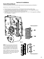
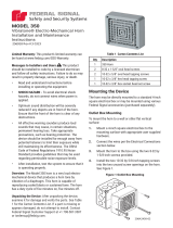
Front of Hood Mount
The Fire Door Operator can be assembled for right-hand or left-hand mounting Front of Hood Fig. 1.
Right hand view is shown, left hand mount is mirror image.
1) Determine operator mounting location, including desired hoist release cable routing.
2) Install two attachment brackets to operator using the six 5/16”-18 x 3/4” carriage bolts and nuts
provided. The attachment brackets must be turned inward. Fig 1.
3) Attach operator to main mounting bracket using the four 5/16”- 18 X 1-1/4” carriage bolts and ange
nuts using option 1 or option 2.
Section 4: Installation
NOTE: The operator output shaft extends
3-7/8” on each side of the operator frame.
It can be adjusted side to side, to increase/
decrease the eective shaft length. Adjust
by loosening the set screws in the shaft set
collars and sprocket, moving the shaft and re-
tightening the set screws. Be sure the bearings
are fully seated in the side frames before re-
tightening the set screws.
Mounting Option 1
Mounting Option 2
Figure 1

4.2
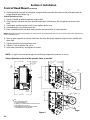
Front of Hood Mount (Continued)
4) Attach operator assembly to head plate using hardware provided. Note the position of bracket slots for
proper bracket orientation. Fig. 2.
Attach Operator to Door.
1) Attach 12 tooth sprocket to operator output shaft.
2) Align keyways and insert key into sprocket and output shaft keyway. Do not tighten set screw at this
time.
3) Attach door sprocket to door shaft. Do not tighten at this time.
4) Assemble chain using chain master link.
5) Place assembled chain over door shaft sprocket and around the 12 tooth sprocket.
6) Raise or lower operator to remove slack from the chain. Be certain operator output shaft is parallel with
door shaft.
7) Tighten operator mounting bracket nuts.
8) Tighten 12 tooth sprocket set screws.
9) Insert door sprocket key and tighten set screws.
Section 4: Installation
NOTE: Hand tighten bracket with head plate nuts. Adjusting the mounting plate position to tension the drive chain will be required later
in the installation process.
Figure 2
NOTES:
1. VERIFY VOLTAGE, PHASE & MOUNTING.
2. ALL OPTIONS ARE AN ADDED COST.
3. A CLEARANCE OF 6" SHOULD BE ALLOWED FOR ACCESS TO ELECTRIC BOX.
4. CONTROL VOLTAGE IS A NEC CLASS 2 CIRCUIT.
5. IT IS RECOMMENDED THAT THE OPERATOR BE BRACED TO THE WALL
FOR STABILIZING AND A SAFETY CABLE ATTACHED.
22 3/8"
(OPERATOR HEIGHT)
3 1/2"
14 1/8"
15 3/16"
14 3/16"
5 1/8"
6 13/16"
MOUNTING
OPTION 1
#347372
POWER SUPPORT
BRACKET
16"
(OUTPUT SHAFT LENGTH)
16 13/16"
(OPERATOR WIDTH)
4 11/16"
(OPERATOR
SIDE ROOM)
STANDARD FUSE LINK SWITCH
LOCATION (SEE MANUAL
FOR INSTALLATION OF
SASH CHAIN)
OPTIONAL
FUSE LINK
SWITCH
LOCATION
8 9/16"
MOUNTING
OPTION 2
#347372
POWER SUPPORT
BRACKET
* Mount Sprockets as close to the operator frame as possible.
NOTE: It is highly recommended to apply thread locking compound to sprocket set screws.

4.3
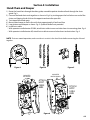
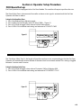
Hand Chain and Keeper
1) Route the hand chain through the chain guide, around the pocket wheel and back through the chain
guide. Fig.3.
2) Connect the hand chain ends together as shown in Fig 4. by twisting open the last link on one end of the
chain, and slipping the last link on the opposite end onto the open link.
3) Twist open link closed again.
4) Mount chain keeper to wall in line with chain approximately 4 feet from oor.
5) Loop chain around keeper as shown. Fig. 5. Optional Padlock not provided.
6) Install hoist cable.
• With operator installed motor DOWN, attach hoist cable to cam arm hole closest to mounting plate. Fig. 6.
• With operator installed motor UP, attach hoist cable to cam arm hole closest to electric box. Fig. 6.
Section 4: Installation
NOTE: To insure smooth operation, make sure there is no twist in the hand chain before connecting the link ends
together.
MOUNTED
MOTOR UP
MOUNTED
MOTOR DOWN
ATTACH
HOIST
CABLE
HERE
ATTACH
HOIST
CABLE
HERE
Figure 3 Figure 4 Figure 5
Figure 6

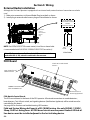
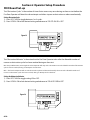
4.4
1) Move Fusible Link Switch from top of Electric Box to Side if necessary depending on installation of
operator direction or side. FIG. 1.
2) Remove E-Ring to remove switch assembly.
3) Remove plug and insert into hole where fuse link switch was removed.
4) Install fuse link switch assembly into desired connection point and install E-Ring.
5) Follow all recommendations for release chain installation per NFPA 80. Note direction of pull on switch.
FIG. 3.
6) Remove fuse link switch pin to tension chain. Ensure switch holds tension on chain and does not contact
internal switch. FIG. 3.
The Fire Door Operator provides a connection for the Fusible Link from the Fire Door. If tension is lost from chain,
operator will release its clutch and door will drop.
Fusible Link Switch
Section 4: Installation
E-Ring
Plug
Fuse Link
Switch
Assembly
Fuse Link
Switch Pin
Switch Mount
Top
Switch Mount
Either Side
Tensional Direction
FIG. 1
FIG. 2
Wall Mount Bracket
Fusible Link
Turnbuckle
Sash
Chain
Example
Remove
Pin
FIG. 3
NOTE: If operator and headplate sway during door operation, bracing is necessary. Using
structural angle, diagonally brace from operator mounting bracket or from front portion of
headplate back to wall.

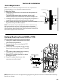
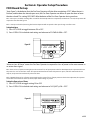
4.5
Clutch Adjustment
To Adjust the Clutch
1) Decrease the compression on the clutch until the operator will
not lift the door.
• Turning the adjustment castle nut counter-clockwise will
decrease compression and clockwise will increase compression.
2) Gradually increase compression until the operator will perform a
complete open and close cycle without clutch slippage.
3) Insert a cotter pin through the adjustment castle nut and bend a
leg of the cotter pin to hold it in place.
Section 4: Installation
NOTE: The clutch is intended to provide protection for the door, the operator and
associated equipment. It is not intended for entrapment protection.
NOTE: Periodically check the system for proper clutch action. If clutch starts to slip
after working properly for some time , check manual operation of door BEFORE
adjusting clutch. The door may not be operating freely or the counterbalance spring
may need adjusting. Repairs and adjustments must be performed by a trained service
representative using proper tools and instructions.
CLUTCH PULLEY
WASHER
COTTER PIN
ADJUSTING NUT
CLUTCH
PAD
CLUTCH
PLATE
SPRING
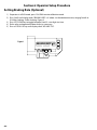
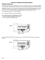
1) Unplug FDO module ribbon harness from main
control board plug connector.
2) Remove the two screws mounting the FDO
module to plate.
3) Use the two screws included with the auxiliary
board and mount to plate where FDO module
was.
4) Plug auxiliary board ribbon harness into plug
connector on main control board.
5) Reinstall FDO module onto plate just above
the auxiliary board.
6) Plug FDO module ribbon harness into
connector on auxiliary board.
Only one auxiliary board can be used with this opener.
Optional Auxiliary Board (AOM or TCM)
FDO Module
AUX Board
Ribbon
Harness
Plug
NOTE: Additional menu items will appear during programming. See the instructions included with the Auxiliary
board to see changes.

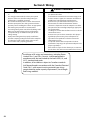
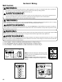
5.1
Section 5: Wiring
WARNING
• DO NOT apply power to operator until instructed to do
so.
• It is strongly recommended, and may be required
by law in some areas, that line voltage wiring be
performed by a qualied electrician.
• Be sure that electrical power has been disconnected
from the input power wires being connected to the
operator prior to handling these wires. An appropriate
lock-out/tag-out procedure is recommended.
• Line voltage wiring must meet all local building codes.
• Make sure operator voltage, phase and frequency
nameplate ratings are identical to the job site line
voltage ratings.
• Input power wiring must be properly sized for the
operators amperage rating located on the nameplate.
• To reduce the risk of electric shock, make sure the
chassis of this unit is properly grounded.
!
• NE PAS mettre sous tension tant que l’instruction n’est
pas donnée de le faire.
• Il est fortement recommandé voire même exigé par la
loi dans certaines régions, de contacter un électricien
qualié pour l’acheminement du l électrique.
• Assurez-vous que l’alimentation électrique a été
déconnectée des câbles d’alimentation d’entrée
connectés à l’opérateur avant de manipuler ces câbles.
Une procédure de verrouillage/étiquetage appropriée
est recommandée.
• Le câblage au secteur doit satisfaire à tous les codes de
construction locaux.
• Assurez-vous que les valeurs nominales de la plaque
signalétique pour tension, phase et fréquence de
l’opérateur correspondent à celles des tensions de
l’alimentation sur site.
• La capacité d’entrée doit correspondre à la valeur
nominale de l’ampérage des opérateurs indiquée sur la
plaque signalétique.
• Pour réduire le risque de choc électrique, assurez-vous
que le châssis de l’unité est correctement mis à la terre.
AVERTISSEMENT
!
Installation of all wiring and connections, including Power
Limited Class 1 and Class 2 circuits, shall be performed in
accordance with, but not limited to, the latest NFPA, UL, and
N.E.C. standards and codes.
In addition, all installations subject to Canadian standards
shall be performed in accordance with the Canadian Electrical
Code, Part 1, with respect to wiring material type, wiring
gauge related to power capacity requirements, circuit length
and wiring methods.

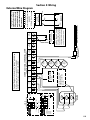
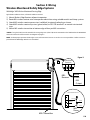
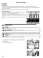
5.2
External Wire Diagram
Section 5: Wiring
OPEN CLOSE
N-O
REVERSE
N-O
REVERSE
ODC
STB
ODC
STB
EXT
INTLK
EXT
INTLK
OPEN
CLOSE
STOP
1-BTN
STATION
KEY
SWITCH
STATION
CARD
READER
O/C
PULL
SWITCH
RELAY
GND
NOM
+ 24VDC
N/O
N/O
N/O
N/O
3-BUTTON
STATION
MONITORED SENSING EDGEINTERFACE MODULE
(OPAKMEIX.S)
RADIO
REMOVE JUMPER
WHEN INSTALLING
EXTERNAL INTERLOCK
CONTROL SIGNAL TERMINAL STRIP
MULTIPLE 3-BUTTON
STATION INSTALLATIONS
REQUIRE THE STOP
BUTTON TO BE WIRED
IN SERIES
REMOVE JUMPER
IF STOP BUTTON
IS USED
EXT
RADIO
CONNECTOR
PIGTAIL
LINE IN
POWER CONNECTIONS
L1/ L1
N/ L2
GND
120V
208/230V
LINE
(HOT)
NEUTRAL
LINE 1
LINE 2
L1/ L1
L1/ L2
GND
L3/ L3
(HOT)
(HOT)
(HOT)
SINGLE
PHASE
3
PHASE
STOP GND 1-BTN
Blue
Orange
Yellow
Chassis
208/230
460
575
Special Application
External Radio Terminal
0-40 VDC
250mA. Max Current
Power-Limited Class 2 Supply 0-40VDC
External Radio connections
are Non-Power-Limited.
All connections are to be
made within 20ft. (6.1M),
enclosed in conduit and in
the same room.
OPEN, CLOSE, STOP and 1-BTN terminals are 40VDC,
20mA MAX. ODC STB Terminals are 40VDC, 150mA MAX.
N/O Reverse Terminals are 40VDC, 10mA MAX.
EXT INTLK Terminals are 40VDC, 2.5mA MAX.
EXT INTLK connections
are Non-Powered-Limited.
All connections are to be
made within 20 ft. (6.1M)
and enclosed in conduit
and in the same room.

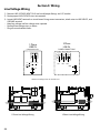
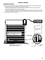
5.3
1) Remove LINE VOLTAGE INPUT PLUG and install proper ttings and 1/2”conduit.
2) Route proper LINE VOLTAGE wires into operator.
3) Locate LINE INPUT terminals on circuit board. Using correct connectors, attach wires to LINE INPUTS, and
GROUND terminal.
• Keep low voltage and line voltage wires separate.
• Route all line voltage wires as shown.
• Plug all unused conduit holes.
Line Voltage Wiring
Section 5: Wiring
1 Phase Line Voltage Wiring 3 Phase Line Voltage Wiring
Route Line Voltage wires in shaded areas
L1/L1
N/L2
GND
POWER CONNECTIONS
LINE
(HOT)
NEUTRAL
LINE 1
LINE 2
115V
208V
230V
1 Phase
LINE IN
3 Phase
LINE IN
POWER CONNECTIONS
L1
L2
GND
LINE 1
LINE 2 LINE 3
L3

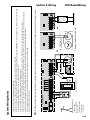
5.4
1) Connect all LOW VOLTAGE control circuit wires using 1/2” conduit or exible convoluted tubing.
• Keep low voltage and line voltage wires separate.
• Route all low voltage control wiring as shown. This includes all control circuit wires such as wall
controls, timers and single button input devices as well as safety circuit wiring.
• Route FDO Control Board wires through opposite side of unit.
• Plug all unused conduit holes.
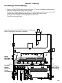
Low Voltage Control Wiring
Section 5: Wiring
Route Low Voltage Control & FDO Board wires in shaded areas.
Keep FDO Board and Control Wires separated.
FDO
BOARD
Low Voltage
Power Limited
Circuit Wiring
Fire Door
Module
Non-Power
limited
Circuit Wiring

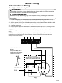
5.5
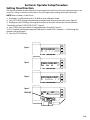
1) For a single 3 - button installation, make connections as shown in Fig. 3.
2) For single button accessory controls, make connections as shown in Fig. 4.
3) For a multiple 3 - button installations, make connections as shown in Fig. 5.
Wall Controls
Section 5: Wiring
OPEN
CLOSE
STOP
CONTROL SIGNAL TERMINAL STRIP
NOTE
JUMPER BETWEEN
STOP AND GND
TERMINALS MUST
BE REMOVED
OPEN CLOSE STOP GND
3-BTN
Station
Entrapment Warning
Placard
CONTROL SIGNAL TERMINAL STRIP
1-BTN
Station
Key
Switch
Station
Card
Reader
Open/Close
Pull Switch
STOP GND 1-BTN
ODC
STB
CONTROL SIGNAL TERMINAL STRIP
OPEN
CLOSE
STOP
OPEN
CLOSE
STOP
OPEN CLOSE STOP GND
NOTE: JUMPER
BETWEEN STOP
AND GND TERMINALS
MUST BE REMOVED
3-BTN
STATION
3-BTN
STATION
NOTE: If an External STOP button is NOT being installed,
a jumper wire must be installed between the “STOP” and
“GND” terminals as shown.
NOTE: Low voltage wiring can be run a maximum of
1000 feet. DO NOT use long distance wiring kits on this
operator.
WARNING:
Single button input will reverse the door to the up limit. A timer will resume downward travel if set. Single button input will NOT
stop the door. Use of an emergency stop button is strongly recommended for single button input applications.
!
AVERTISSEMENT:
Une entrée à bouton unique inversera la porte vers la limite supérieure. Une minuterie reprendra le parcours vers le bas, si réglé.
Une entrée à bouton unique N’ARRÊTERA PAS la porte. L’utilisation d’un bouton d’arrêt d’urgence est fortement recommandée
pour les applications d’entrée à bouton unique.
!
!
!
WARNING:
AVERTISSEMENT:
Before momentary contact control can be used on the CLOSE button, a monitored external reversing device such as a sensing
edge switch must be used. See pages 5.7-5.8 for installation of entrapment protection devices.
Avant d’utiliser la commande à contact momentané sur le bouton FERMETURE, un dispositif d’inversion externe surveillée tel
qu’un système de un commutateur de détection de bord doit être utilisé. Voir l’installation des dispositifs de protection contre
le coincement en pages 5.7-5.8.
WARNING:
!
AVERTISSEMENT:
!
• Wall Control(s) must be located so that the door is within sight of the user and is far enough from the door, or positioned
such that the user is prevented from coming in contact with the door while operating controls.
• Attach the Warning placard adjacent to the Wall Control. Fig. 3A.
• La ou les commandes murales doivent être situées de telle sorte que l’utilisateur puisse voir la porte et positionnées de
telle sorte que l’utilisateur ne puisse pas entrer en contact avec la porte lorsqu’il se sert des commandes.
• Fixez le poster d’avertissement à côté de la commande murale. Fig. 3A.

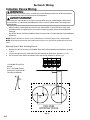
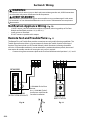
5.6
Interlock Switches
Section 5: Wiring
INSTALLING EXTERNAL
INTERLOCK
CONTROL SIGNAL TERMINAL STRIP
* REMOVE JUMPER WHEN
*
NOTE: If External Interlock is used, THE
JUMPER WIRE BETWEEN THE EXT INTLK
TERMINALS MUST BE REMOVED.
STANDARD
SLIDELOCK
TRACK
SWITCH
(N.C.)
Switches must
be set in
the field.
Side lock interlock:
Should be open when door is locked.
Closed when door is unlocked.
A
ODC
STB
ODC
STB
N-O
REVERSE
N-O
REVERSE
EXT
INTLK
EXT
INTLK
1) Optional external interlock switches are required with some Rolling Steel Doors to prevent the door
from operating under certain conditions including the following:
• If the door is equipped with a functioning door lock, an interlock switch (A) must be installed to
prevent electric operation when the lock is engaged.
• If the door is equipped with a pedestrian pass-through door, an interlock switch (B) must be installed
at the pass-through door in order to prevent electrical operation when the pass-through door is open.
2) The switches must be set in the eld.

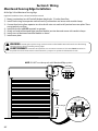
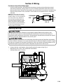
5.7
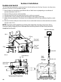
1/2 Door Height
+ 12in.
COIL
CORD
Monitored
Safety Edge
Red Wires
MillerEdge®
Interface Module
Install
Black
White
Control Wire
Terminals
ODC
STB
ODC
STB
Junction
Box
1) Mount junction box to wall One half the door height plus 12 inches from oor.
2) Install Hard-wiring from operator and coil cord to junction box and secure with conduit clamps.
3) Connect hard-wiring from operator to coil cord with wire nuts and install junction box cover plate. These
are not polarity sensitive.
4) Install hard-wires to ODC STB terminals in operator.
5) Attach coil cord to Monitored Edge Interface Module junction box and secure with conduit clamps.
6) Install wires to Monitored Interface Module as shown.
7) Install cover plate.
Right hand installation shown, Left hand installation mirrored
MillerEdge® Wired Monitored Sensing Edge
Monitored Sensing Edge Installation
Section 5: Wiring
WARNING: Actuating the operator using constant contact on the CLOSE button will override non-functioning
external reversing devices, including sensing edges.
AVERTISSEMENT: L’activation de l’opérateur avec un contact constant sur le bouton FERMER annulera les
dispositifs de renversement externes non fonctionnels, y compris les systèmes de détection des bords.
!
!
NOTE: DO NOT use take up reels with Monitored Edge systems
La page est en cours de chargement...
La page est en cours de chargement...
La page est en cours de chargement...
La page est en cours de chargement...
La page est en cours de chargement...
La page est en cours de chargement...
La page est en cours de chargement...
La page est en cours de chargement...
La page est en cours de chargement...
La page est en cours de chargement...
La page est en cours de chargement...
La page est en cours de chargement...
La page est en cours de chargement...
La page est en cours de chargement...
La page est en cours de chargement...
La page est en cours de chargement...
La page est en cours de chargement...
La page est en cours de chargement...
La page est en cours de chargement...
La page est en cours de chargement...
La page est en cours de chargement...
La page est en cours de chargement...
La page est en cours de chargement...
La page est en cours de chargement...
La page est en cours de chargement...
La page est en cours de chargement...
La page est en cours de chargement...
La page est en cours de chargement...
La page est en cours de chargement...
La page est en cours de chargement...
La page est en cours de chargement...
La page est en cours de chargement...
La page est en cours de chargement...
La page est en cours de chargement...
La page est en cours de chargement...
La page est en cours de chargement...
La page est en cours de chargement...
La page est en cours de chargement...
La page est en cours de chargement...
La page est en cours de chargement...
La page est en cours de chargement...
La page est en cours de chargement...
La page est en cours de chargement...
La page est en cours de chargement...
La page est en cours de chargement...
La page est en cours de chargement...
La page est en cours de chargement...
La page est en cours de chargement...
-
 1
1
-
 2
2
-
 3
3
-
 4
4
-
 5
5
-
 6
6
-
 7
7
-
 8
8
-
 9
9
-
 10
10
-
 11
11
-
 12
12
-
 13
13
-
 14
14
-
 15
15
-
 16
16
-
 17
17
-
 18
18
-
 19
19
-
 20
20
-
 21
21
-
 22
22
-
 23
23
-
 24
24
-
 25
25
-
 26
26
-
 27
27
-
 28
28
-
 29
29
-
 30
30
-
 31
31
-
 32
32
-
 33
33
-
 34
34
-
 35
35
-
 36
36
-
 37
37
-
 38
38
-
 39
39
-
 40
40
-
 41
41
-
 42
42
-
 43
43
-
 44
44
-
 45
45
-
 46
46
-
 47
47
-
 48
48
-
 49
49
-
 50
50
-
 51
51
-
 52
52
-
 53
53
-
 54
54
-
 55
55
-
 56
56
-
 57
57
-
 58
58
-
 59
59
-
 60
60
-
 61
61
-
 62
62
-
 63
63
-
 64
64
-
 65
65
-
 66
66
-
 67
67
-
 68
68


Genie GCL Fire Door Operator / Installation Manual
- Catégorie
- Porte de garage
- Taper
- Operator / Installation Manual
dans d''autres langues
- English: Genie GCL Fire Door
Documents connexes
-
Genie TCM Manuel utilisateur
-
-
-
-
Genie GCL-J&H 1HP Guide d'installation
-
Genie GCL-GT Operator / Installation Manual
-
-
Genie GCL-MT Manuel utilisateur
-
Genie GCL-T Operator / Installation Manual
-
Autres documents
-
LiftMaster LMWEKITU Manuel utilisateur
-
 Federal Signal 350 Vibratone® Horn Manuel utilisateur
-
Grizzly G8696 Le manuel du propriétaire
-
LiftMaster LC36M Manuel utilisateur
-
 Nice HySecurity SlideSmart CNX Slide Gate Operator Guide d'installation
-
Honeywell Modutrol IV M6294F1009-F Information produit
-
Blodgett MT2136E/AB Mode d'emploi
-
Dormakaba LA GARD 700 Series Mode d'emploi
-
Gentex WGESA24 Series Manuel utilisateur
-
BEA UL LISTED MAGLOCKS Mode d'emploi

