Honeywell Modutrol IV M6294F1009-F Information produit
- Taper
- Information produit

PRODUCT DATA
Put Bar Code Here
63-2629EF-01
Series 61 and Series 62
Modutrol IV™ Motors
APPLICATION
The Series 61 and Series 62 Modutrol IV™ Motors are
three-wire spring return and non-spring return floating control
motors. Use these motors with controllers that provide a
switched spdt or floating output to operate dampers or valves.
The Series 62 motors have an internal electrically isolated
feedback potentiometer that provides indication of the motor
shaft position and can be used for slaving Series 90 Motors or
rebalancing an external control circuit.
FEATURES
• Replaces M644, M944B,E,G,H,J,K,R,S and
M945B,C,G,K,L,AD Motors.
• Integral junction box provides NEMA 3 weather
protection.
• Integral spring return returns motor to normal position
upon power failure.
• Motor and circuitry operate from 24 Vac. Models
available with factory installed transformer, or a field
added internal transformer.
• Quick-connect terminals are standard—screw terminal
adapter is available.
• Adapter bracket for matching shaft height of older
motors is available.
• Motors have field adjustable stroke (90° to 160°).
• Die-cast aluminum housing.
• Integral auxiliary switches are available factory
mounted, or can be field added.
• Nominal timing standard of 30 seconds (90° stroke),
and 60 seconds (160° stroke). Other timings available.
• Spring return motors can operate valve linkages from
power end or auxiliary end shafts for normally closed
or normally open valve applications.
• All models have dual shafts (slotted and tapped on
both ends).
• All models have auxiliary switch cams.
• Fixed torque throughout the entire voltage range.
• Motors are designed for either normally open or
normally closed valves and dampers.
• Series 62 models include electrically isolated
potentiometer that provides shaft position indication.
• Series 62 TRADELINE models have linear feedback,
configurable for slaving Series 90 Motors.
SPECIFICATIONS
Models: TRADELINE models are selected and packaged to
provide ease of stocking, ease of handling and maximum
replacement value. TRADELINE model specifications are the
same as those of standard models unless specified otherwise.

SERIES 61 AND SERIES 62 MODUTROL IV™ MOTORS
63-2629EF—01 2
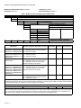
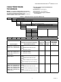
Modutrol IV Order Number Guide: See Table 1.
Dimensions: See Fig. 2.
Feedback See Table 2.
Electrical Ratings: See Table 4.
Table 1. Modutrol IV Series 2 Version Order Number Guide.
Table 2. Series 62 Feedback Characteristics
NOTE: Limited models available in Europe, check your local representative for the availability.
M Motor
61 Floating Control
62 Floating Control with feedback
8 60 lb-in. Spring Return 150 lb-in. Non-Spring Return
9 — 300 lb-in. Non-Spring Return
2 Dual-ended shaft Normally Closed Spring Return
4 Non-Spring Return
5 Normally Closed Spring Return
A 0 Auxiliary Switches Adjustable Stroke Normally Closed
B 1 Auxiliary Switch
C 2 Auxiliary Switches
D 0 Auxiliary Switch
E 1 Auxiliary Switch
F 2 Auxiliary Switches
M 61 8 4 A XXXX See Catalog for Complete O.S. Number
OS Number
Feedback Resistance
(Resistance between terminals T, G, and Y)
Sensitivity
Adjustment
Linear
Feedback
Series 90 Slaving
Shunt Resistor
M6284D1000-S, M6284D1026-S,
M6284D4004-S, M6285A1005-S,
M6285A1054-S, M6285A4009-S
TG = 370-2400-920 ohm curve (non-linear)
TY = 920-2400-370 ohm curve (non-linear)
YG = 600 ohms constant
No No 187 Ohm
M6274F1009-F, M6284F1070-F,
M6284F1078-F, M6285F1001-F,
M6294F1009-F, M6294F1017-F,
M6284D1032-F
TG = 0-10K ohm (linear)
TY = 10-0K ohm (linear)
YG = 10K ohms constant
No Yes Not Available
M6284A1071-S, M6284A1089-S,
M6284C1028-S
TG = 370-2350-630 ohm curve (non-linear)
TY = 630-2350-370 ohm curve (non-linear)
YG = 196 ohms constant for 160° stroke,
346 ohms constant for 90° stroke.
Yes No 274 Ohm
M6284A1030-S, M6284A1055-S,
M6284A1097-S, M6284B1004-S,
M6284C1010-S, M6284C1044-S,
M6284F1013-S, M6284F1039-S,
M6285A1039-S, M6285A1047-S,
M6285C1001-S, M6294B1036-S,
M6294D1008-S
TG = 370-2300-550 ohm curve (non-linear)
TY = 550-2300-370 ohm curve (non-linear)
YG = 119 ohms constant for 160° stroke,
224 ohms constant for 90° stroke.
Yes No Not Necessary
M6284F1062-S TG = 370-2800-1990 ohm curve (non-linear)
TY = 1990-2800-370 ohm curve (non-linear)
YG = 1800 ohms constant
No No Not Available
* All resistance ranges given in the "Feedback Resistance" column are for 160° motors. For a 90° motor that range will be
truncated to either the first half if it’s an asymmetrical motor (for example, a -F would go from 0-5K) or truncated to the middle half
if it's a symmetrical motor (for example, a -F motor would go from 2.5-7.5K).
“-S” Non-linear Feedback for Slaving Series 90 Mod IV Motor
“-F” 0-10K Feedback
Both the "-S" and the "-F" can be used as a voltage divider. When a constant voltage is applied to YG, a voltage signal can be
read over TG that varies linearly with the stroke of the motor from 4-96% of the constant voltage applied to YG, for a 160° motor
only. For 90° asymmetrical motor the signal from TG varies from 4-56% and for a 90° symmetrical motor the signal from TG
varies from 24-76%. A signal can also be read from TY which is the opposite of the signal from TG.

SERIES 61 AND SERIES 62 MODUTROL IV™ MOTORS
3 63-2629EF—01
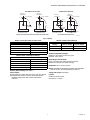
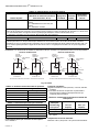
Fig. 1. Stroke
Table 3. Primary 50017460-001 Color Code.
Table 4. Power Consumption Ratings.
Auxiliary Switch Ratings: See Table 5.
Control Inputs:
Floating three-wire (Series 60): drive open, hold, drive closed.
Series 62 models include an internal, electrically isolated
feedback potentiometer that provides shaft position
indication.
Table 5. Auxiliary Switch Ratings.
Ambient Temperature Ratings:
Maximum: 150°F (66°C) at 25% duty cycle.
Minimum: -40°F (-40°C).
Dead Weight Load On Shaft:
Power or Auxiliary End: 200 lb (90.8 kg) maximum.
Maximum Combined Load: 300 lb (136 kg).
Crankshaft: 3/8 in. (9.5 mm) square.
Stroke: Adjustable Stroke Models: Available field-adjustable
from 90° to 160°. (See Stroke Setting procedure.)
Timing And Torque: See Table 6.
Lifetime
60,000 Full Stroke Cycles
Repositions: 1.5 million
FULLY OPEN
90 DEGREE STROKE 160 DEGREE STROKE
M31079
VERTICAL
REFERENCE
FULLY CLOSED
160
10
VERTICAL
REFERENCE
FULLY CLOSED
90
10
FULLY OPEN
VERTICAL
REFERENCE
VERTICAL
REFERENCE
FULLY CLOSED
FULLY OPEN
FULLY
CLOSED
FULLY
OPEN
90 DEGREE STROKE 160 DEGREE STROKE
NON-SPRING RETURN MOTORS
160
10
90
45
SPRING RETURN MOTORS AND NON-SPRING RETURN MOTORS
ASYMMETRICAL MOTORS
SYMMETRICAL MOTORS
Power Consumption
Lead Color Primary Voltage
Brown 24 VAC
White 120 VAC
Blue 230 VAC
Black Common
Power Consumption
Model Number VA Rating
M6184A 15
M6184B 10
M6184D 15
M6184F 15
Single Contact
Rating
a
120V (in Amps) 240V (in Amps)
Full Load 7.2 3.6
Locked Rotor 43.2 21.6
a
40 VA pilot duty, 120/240 Vac on opposite contact.

SERIES 61 AND SERIES 62 MODUTROL IV™ MOTORS
63-2629EF—01 4
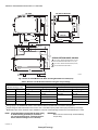
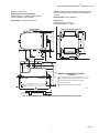
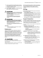
Fig. 2. Series 61 and 62 Modutrol IV Motor mounting dimensions in inches (mm).
Table 6. Series 61 and 62 Modutrol IV Motor Timing and Torque Ratings.
NOTE: Torque designation corresponds to torque rating
at standard timing (nominally 60 seconds for
160° and 30 seconds for 90° except for 300 lb-in.
motors that have timings of 2 or 4 minutes).
IMPORTANT
Never use motor continuously at the Breakaway
Torque rating.
Nominal Timing
a
in sec
Rated Torque in lb-in. (N•m)
b
Normal Running Torque Breakaway Torque
c
90° Stroke 160° Stroke Spring Return Non-Spring Return Spring Return Non-Spring Return
15 30 — 75 (8.5) — 150 (17.0)
30 60 60 (6.8) 35 (4.0) 120 (13.6) 70 (7.9)
150 (17.0) 300 (34.0)
60 120 300 (34.0) 600 (68.0)
120 240 —
—
150 (17.0) 300 (34.0)
a
Timings apply to all TRADELINE models. Some OEM models are available with non-standard timing/torque.
b
Torque ratings for dual-ended shaft motors are the sum of the shaft torques (power-end torque plus auxiliary-end torque).
c
Breakaway torque is the maximum torque available to overcome occasional large loads such as a seized damper or valve.
M18998B
4-7/8
(124)
5-1/2
(140)
13/16
(20)
4-1/16 (103)
1/4
(7)
1-1/2 (37)
4-1/16 (103)
JUNCTION
BOX
MOTOR
AUXILARY
END
POWER
END
ADAPTER
BRACKET
2-9/16
(66)
5-3/8
(137)
6-7/16
(164)
9/16 (15)
3/4
(19)
TOP VIEW OF BRACKET TOP VIEW
4-5/8
(116)
4-1/4
(107)
2-5/16
(58)
11/16
(17)
4-7/8 (124)
5-9/16 (141)
1/4 (7)
5-13/16
(148)
1
POWER END
2
3
1-1/2 (37)
3/4
(19)
SPRING RETURN MODEL SHOWN
FOR 60 LB-IN. SPRING RETURN MODELS 8-3/4 (222).
FOR NON-SPRING RETUIRN MODELS 7-5/16 (185).
FOR 60 LB-IN. SPRING RETURN MODELS (SHOWN).
FOR NON-SPRING RETURN MODELS.
1
2
3
13/16
(20)
honeyvell.energy

SERIES 61 AND SERIES 62 MODUTROL IV™ MOTORS
5 63-2629EF—01
Feedback Potentiometer (Series 62 Models Only):
TRADELINE Models (Can be shunted for slaving a
Series 90 Motor).
Approvals:
Underwriters Laboratories Inc. Listed: File No. E4436, Guide
No. XAPX. For USA and Canada.
U.S. Patents: pending
Accessories:
220736A Internal Auxiliary Switch Kit; one switch, can be
field-installed.
220736B Internal Auxiliary Switch Kit; two switches, can be
field-installed.
220738A Adapter Bracket raises motor shaft height by 3/4
inch (19 mm) to match that of previous Modutrol Motor
models.
220741A Screw Terminal Adapter converts the standard
quick-connect terminals to screw terminals.
221455A Infinitely Adjustable Crank Arm, can rotate through
downward position and clear motor base without requiring
an adapter bracket.
4074ERU Weatherproofing Kit provides NEMA 3 rating for
Modutrol IV Motors mounted in position other than upright.
50017460-001 Internal Transformer; 24/120/230 Vac 50/60 Hz
primary, 24 Vac secondary, quick connect terminals.
50017460-003 Internal Transformer; 120 Vac 50/60 Hz pri-
mary, 24 Vac secondary, quick connect terminals.
7617ADW Crank Arm, can rotate through downward position
and clear motor base without requiring an adapter bracket.
Q100 Linkage connects Modutrol Motor to V51 Butterfly
Valve. Requires the 220738A Adapter Bracket.
Q181 Auxiliary Potentiometer for sequence or unison control
of 1 to 4 additional modulating (Series 90) motors.
Q5001 Bracket and Linkage Assembly connects Modutrol IV
Motor to water or steam valve.
Q605 Damper Linkage connects motor to damper. Includes
motor crank arm.
Q607 External Auxiliary Switch controls auxiliary equipment
as a function of motor position.
ES650-117 Explosion-Proof Housing encloses motor for use
in explosive atmospheres. Not for use with Q5001 (or any
other valve linkages). Order separately from Nelson Enclo-
sures. To order, contact:
EGS Enclosures in Houston, TX
Karen Barfield 281-774-3763
http://appletonelec.com
Part number ES-650-117
You need to order a 7617DM coupling assembly from
Honeywell to use with the cover.
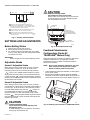
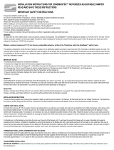
INSTALLATION
When Installing this Product...
1. Read these instructions carefully. Failure to follow them
could damage the product or cause a hazardous
condition.
2. Check the ratings given in the instructions and on the
product to make sure the product is suitable for your
application.
3. Installer must be a trained, experienced service
technician.
4. After installation is complete, check out product
operation as provided in these instructions.
CAUTION
Electrical Shock or Equipment Damage Hazard.
Can shock individuals or short equipment
circuitry.
Disconnect all power supplies before installation.
Motors with auxiliary switches can have more than one
disconnect.
CAUTION
Equipment Damage Hazard.
Can damage the motor beyond repair.
Never turn the motor shaft by hand or with a wrench.
Forcibly turning the motor shaft damages the gear
train and stroke limit contacts.
IMPORTANT
Always conduct a thorough checkout when
installation is complete.
Location
Allow enough clearance for accessory installation and motor
servicing when selecting a location (see Fig. 2). If located
outdoors, use liquid-tight conduit connectors with the junction
box to provide NEMA 3 weather protection. If mounted
outdoors in a position other than upright, install a 4074ERU
Weatherproofing Kit and liquid-tight connectors to provide
NEMA 3 protection.
CAUTION
Motor Damage Hazard.
Deteriorating vapors and acid fumes can damage
metal parts.
Install motor in areas free of acid fumes and other
deteriorating vapors.
In excessive salt environments, mounting base and screws
should be zinc or cadmium plated, not stainless steel or brass.
Use the 220738A Adapter Bracket for mounting on these
surfaces.
Mounting
Use the following guidelines for proper motor mounting:
• Always install motors with the crankshaft horizontal.
• Mounting flanges extending from motor housing base are
drilled for 1/4 inch (6.4 mm) machine screws or bolts.
• Non-Spring Return Motors are shipped from the factory in
the closed position (at the limit of counterclockwise
rotation, as viewed from the power end of the motor).
Adapter Bracket
The 220738A Adapter Bracket, positioned between the motor
and the equipment, raises motor shaft height by 0.75 in.
(19 mm) to match that of previous Modutrol Motor models.
The following applications require this bracket:
• Q607 External Auxiliary Switch.
• Damper linkage applications require added clearance to
allow:

SERIES 61 AND SERIES 62 MODUTROL IV™ MOTORS
63-2629EF—01 6
— Crank arm rotation through the downward position.
— Sufficient damper linkage to reach the motor shaft.
• All valve linkages except the Q5001.
NOTE: When the bracket is not used in a replacement
application, the damper linkage requires adjust-
ment for the new shaft position.
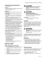
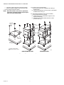
To mount the motor with the bracket:
1. Mount the bracket to the equipment with existing or
standard bolts.
2. Using the provided bolts, mount the motor to the bracket
threaded holes. See Fig. 3.
For valve linkage applications (other than the Q5001):
1. Mount the bracket to the linkage.
2. Position the motor on the bracket to align the motor
shaft with the linkage.
3. Attach the motor to the bracket with the four bolts
provided. See Fig. 4.
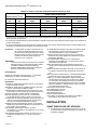
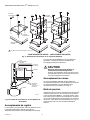
Fig. 3. Mounting the motor with an adapter bracket.
M18999
EQUIPMENT
BASE
ADAPTER
BRACKET
STANDARD
BOLTS (4)
MOTOR
BOLTS
PROVIDED (4)
WIRING
BOX
NON-SPRING RETURN
SPRING RETURN
1 #12 OR 1/4" ZINC PLATED
MACHINE SCREWS OR BOLTS
1
PO
W
ER
END
POW
ER
END
POW
ER
END

SERIES 61 AND SERIES 62 MODUTROL IV™ MOTORS
7 63-2629EF—01
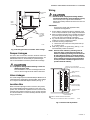
Fig. 4. Mounting the motor on a Q5001 Valve Linkage.
Damper Linkages
The motor does not include a crank arm. Order the crank arm
separately (see Accessories in the Specifications section). For
detailed instructions on the assembly of specific linkages,
refer to the Installation Instructions packed with the linkage.
CAUTION
Equipment Damage Hazard. Stalling a motor can
damage the drive shaft.
Ensure installation of motors and linkages allows the
motor to drive through full stroke without obstruction.
Valve Linkages
The Q100 Linkage requires a 220738A Adapter Bracket for all
valve applications. Applications with the Q5001 Valve Linkage
do not require the 220738A Adapter Bracket (see Fig. 4).
Junction Box
When used with liquid-tight conduit connectors, the junction
box provides NEMA 3 weather protection for the motor. The
junction box, standard with replacement motors, encloses the
terminals and provides knockouts for wiring conduits. Housing
an internal transformer or internal auxiliary switches requires
using a junction box.
Wiring
CAUTION
Electrical Shock or Equipment Damage Hazard.
Can shock individuals or short equipment circuitry.
Disconnect all power supplies before installation.
Motors with auxiliary switches can have more than one
disconnect.
IMPORTANT
All wiring must agree with applicable codes,
ordinances and regulations.
1. Ensure that the voltage and frequency stamped on the
motor correspond with the power supply characteristics.
2. When connecting several motors in parallel, ensure that
the power supply VA rating is large enough to provide
power to all motors used without overloading.
3. Fig. 5 shows that motor terminals are quick-connects
located on top of the printed circuit board.
4. To access the wiring compartment:
a. Remove the four screws from the junction box top.
b. Lift off the cover.
5. Refer to Fig. 6 and 7 for typical wiring, and Fig. 11 for
internal auxiliary switch connections.
NOTE: Reverse motor rotation by switching wires at
either the motor or panel. Reverse rotation on
Series 61 models by reversing wires at terminals
W and B. Reverse rotation on Series 62 models
by reversing wires at terminals 1 and 2 (to correct
motor rotation) and reverse wires at terminals Y
and G (to maintain a feedback signal that corre-
sponds with shaft rotation),
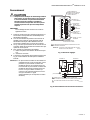
Fig. 5. Terminals and adjustments.
1/4-20 UNC
1 in. LONG
MOUNTING
BOLTS
Q5001
VALVE
LINKAGE
M18994
MOTOR
JUNCTION
BOX
POWER
END OF
MOTOR
VALVE
INNER AUXILIARY
SWITCH
INNER AUXILIARY
SWITCH CAM (BLUE)
POWER
END
OUTER AUXILIARY
SWITCH CAM (RED)
OUTER AUXILIARY
SWITCH
ADJUSTABLE STROKE
POTENTIOMETER
SERIES 62 TERMINAL DESIGNATIONS SHOWN.
NOTE: NOT ALL FEATURES AVAILABLE ON ALL MODELS.
M13600B
Y
T
G
R
4
2
1
3
1
1
SENSITIVITY POTENTIOMETER
(ON SOME SERIES 62 MODELS, SEE TABLE 5)

SERIES 61 AND SERIES 62 MODUTROL IV™ MOTORS
63-2629EF—01 8
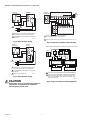
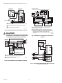
Fig. 6. Series 61 motor wiring.
Fig. 7. Series 62 motor wiring.
CAUTION
Ensure that L1(hot) on the transformer matches 4
(internal hot) on the motor and L2 matches 3
(internal ground) on the motor.
Fig. 8. Connections to R927C or R9107A Relay.
Fig. 9. Series 1 and Series 2 Parallel Application
R
B
W
R
W
B
T2
T1
(HOT) L1
L2
POWER SUPPLY. PROVIDE DISCONNECT MEANS
AND OVERLOAD PROTECTION AS REQUIRED.
TRANSFORMER MAY BE INTERNAL OR EXTERNAL
TO MOTOR.
M17095B
SERIES 60
CONTROLLER
SERIES 61
MOTOR
1
2
1
2
R
B
W
R
1
2
T
G
Y
4
3
(HOT) L1
L2
POWER SUPPLY. PROVIDE DISCONNECT MEANS
AND OVERLOAD PROTECTION AS REQUIRED.
TRANSFORMER MAY BE INTERNAL OR EXTERNAL
TO MOTOR.
FEEDBACK POTENTIOMETER.
M17096A
SERIES 60
CONTROLLER
SERIES 62
MOTOR
1
2
3
1
2
3
W
R
B
G
Y
T
POWER SUPPLY. PROVIDE DISCONNECT MEANS
AND OVERLOAD PROTECTION AS REQUIRED.
CONNECTION REQUIRED ONLY FOR SPRING RETURN MOTORS.
M17098A
SERIES 90
CONTROLLER
R927C OR R9107A RELAY
160 STROKE SERIES 62 MOTOR
Q181A
2
1
T
1
2
2
L1 (HOT)
L2
1
R
W
Y
T
G
2
B
R
W
B
1
4
3
M27044
TRANS
R
C
M62 S2
M62 S1
3
4
R1
T
2
G
Y
3
4
R1
T
2
G
Y
R
W
B
K1
K2
WIRING DIAGRAM M62XX SERIES 1 AND SERIES 2 PARALLEL APPLICATION
SIZE RELAYS AND TRANSFORMER PER SYSTEM REQUIREMENTS.
ADDITIONAL SERIES 2 OR SERIES 1 MOTORS CAN BE ADDED IN
PARALLEL. DO NOT MIX SERIES 1 AND SERIES 2 IN THE SAME
LINE. ONLY WIRE SERIES 1 WITH SERIES 1 AND SERIES 2 WITH
SERIES 2 IN PARALLEL.
1
2
2
2
1
1
M62 S2
M62 S1
3
1
2
3
1
2

SERIES 61 AND SERIES 62 MODUTROL IV™ MOTORS
9 63-2629EF—01
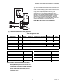
Fig. 10. Series 60 and Series 90 in Slaving Application
The motors in the application need to be all symmetrical or all
asymmetrical. The M62 motor needs to be a “-S” slaving
model, as listed in Table 2. In order to get the correct response
the Series 62 needs the appropriate shunt resistor from Table
2. The motors' potentiometer settings are given in the
configuration table (Table 7) below. When slaving more than
one Series 90 motor use the appropriate resistor table as
indicated by the configuration table and install two resistors to
ONE of the motors (Table 8 and 9). If the motor is the M62
master connect one resistor from terminals T to G and one
from T to Y. If the motor is one of the M90 slaves connect one
resistor from terminals R to B and one from R to W.
NOTE: More than 6 slaves is not recommended.
Table 7. Configuration Table
Table 8. Resistor Table 1 Table 9. Resistor Table 2
NOTE: Vibration does not affect Modutrol IV Motor
performance (as it did in earlier Modutrol
Motors). When replacing a motor that was con-
nected to an R927C or R9107A Relay, Honeywell
recommends performing a retrofit to remove the
relay and the old motor. Replace both with one
Series 90 Modutrol IV motor (that is, do not
replace the relay).
M27035
R
1
2
T
G
Y
3
4
M6284
W
R
B
T1
T2
M9184
R (HOT)
C
R (HOT)
R
B
W
SERIES 60
CONTROLLER
C
Symmetrical or
Asymmetrical
Master
Stroke
Slave
Stroke
Master
Stroke Pot
Master
Sensitivity Pot
Slave
Stroke Pot
Slave
Sensitivity Pot
Resistor
Table
Symmetrical 160 160 CW CW CW CW 1
Symmetrical 90 90 CCW CCW CCW CCW 2
Symmetrical 160 90 CCW CW CCW CCW 1
Symmetrical 90 160 Configuration not recommended
Asymmetrical 160 160 CW CW CW CW 1
Asymmetrical 90 90 CCW CW CW CW 1
Asymmetrical 160 90 Configuration not recommended
Asymmetrical 90 160 Configuration not recommended
Number of Slaves in Parallel Resistor Value
1NONE
2 3500 Ohms
3 2000 Ohms
4 1300 Ohms
5 1000 Ohms
6 800 Ohms
Number of Slaves in Parallel Resistor Value
1NONE
2 5000 Ohms
3 2400 Ohms
4 1700 Ohms
5 1400 Ohms
6 1200 Ohms

SERIES 61 AND SERIES 62 MODUTROL IV™ MOTORS
63-2629EF—01 10
.
Fig. 11. Auxiliary switch schematic.
SETTINGS AND ADJUSTMENTS
Before Setting Stroke
1. Remove the top cover from the motor.
2. Disconnect the controller from the motor.
3. For models with an internal transformer (line voltage
motors), ensure that power (and nothing else) remains
connected to the motor.
IMPORTANT
Detach linkage from motor before adjusting stroke.
Adjustable Stroke
Series 61 Adjustable Stroke
When viewing from the power end of the motor, the stroke
potentiometer is to the far left. To set the stroke to 160°
(maximum position) turn the potentiometer fully clockwise
, using a 1/8 in. straight-blade screwdriver. To set the
stroke at 90° (minimum position) turn the potentiometer fully
counter-clockwise . Setting the potentiometer anywhere
between fully clockwise and fully counter-clockwise will set the
stroke between 160° and 90°.
Series 62 Adjustable Stroke
When viewing from the power end of the motor, the stroke
potentiometer is to the far left. The sensitivity potentiometer is
to the far right. To set the stroke to 160° (maximum position)
turn both potentiometers fully clockwise , using a 1/8
inch straight-blade screwdriver. To set the stroke at 90°
(minimum position) turn both potentiometers fully counter-
clockwise . Setting the potentiometer anywhere between
fully clockwise and fully counter-clockwise will set the stroke
between 160° and 90°.
CAUTION
Careless Installation Hazard.
Use of excessive force while adjusting cams
damages the motor.
To avoid damaging motor end switches, set cams by
moving only the screwdriver top.
CAUTION
Equipment Damage Hazard.
Can damage the motor beyond repair.
Never turn the motor shaft by hand or with a wrench.
Forcibly turning the motor shaft damages the gear
train and stroke limit contacts.
Fig. 12. Stroke adjustments setup.
Feedback Potentiometer
Configuration (Series 62
TRADELINE
®
Motors Only)
Select and install a shunt resistors to obtain the appropriate
feedback characteristic for your application. See the
Specifications section for details on feedback resistance
without a shunt resistor.
NOTE: Due to circuit protection components, the resis-
tance cannot be read directly, use a voltage
divider to read the position of the motor.
• Linear feedback provides linear indication of shaft position
with no shunt resistor.
• Slaving a Series 90 Motor requires full-stroke feedback
resistance of 142 ohms. Select and attach the proper shunt
resistor across terminals Y and G (see Table 2 and Fig. 13).
Fig. 13. Attaching a shunt resistor to TRADELINE motors.
BLUE LEAD
YELLOW LEAD
RED LEAD
USE NEC CLASS 1 WIRING UNLESS POWER SUPPLY
MEETS CLASS 2 REQUIREMENTS. TAPE UNUSED LEADS.
ENSURE THE CURRENT DRAW OF THE EXTERNAL CIRCUIT
IS LESS THAN SWITCH CONTACT RATING.
ON TWO-SWITCH MOTORS, SECOND SWITCH HAS BLACK
LEADS WITH BLUE, YELLOW, AND RED TRACERS.
SOME AUXILIARY SWITCH ASSEMBLIES INCLUDE ONLY
RED AND YELLOW LEADS. SOME OTHERS DO NOT INCLUDE
THE YELLOW LEAD.
M17099
1
1
1
2
2
2
2
3
3
M13601
POWER END
OF MOTOR
AUXILIARY
SWITCH CAMS
SENSITIVITY
POTENTIOMETER
(ON SOME SERIES 62
MODELS, SEE TABLE 5)
ADJUSTABLE
STROKE
POTENTIOMETER
3
4
R
1
2
G
Y
M652

SERIES 61 AND SERIES 62 MODUTROL IV™ MOTORS
11 63-2629EF—01
Auxiliary Switches
Adjustable cams actuate the auxiliary switches. These cams
can be set to actuate the switches at any angle within the
motor stroke. Select switch differential of 1° or 10°.
Motors with factory-added auxiliary switches are shipped in
the closed position (fully counterclockwise, as viewed from the
power end). Auxiliary cam default actuates the switches 30°
from fully open with a 1° differential. With the motor in the
closed (fully counterclockwise) position, the auxiliary switch
breaks contacts R-B. See Fig. 11 (or the auxiliary switch
Installation Instructions) for auxiliary switch wiring.
NOTE: Series 2 Motors are shipped with auxiliary switch
cams that permit acceptance of 220736A,B Inter-
nal Auxiliary Switch Kits. Refer to Form no. 63-
2228 for 220736A,B Installation Instructions.
Auxiliary Switch Adjustment
IMPORTANT
When adjusting the auxiliary switch cams use the
following procedure:
1.Insert 1/8 in. screwdriver blade into a slot on cam
and move the screwdriver top as far as possible in
the required direction. See Fig. 14.
2.Repeat step 1 in successive cam slots until the
cam is in the required position.
Use the following procedure to obtain the desired auxiliary
switch settings:
1. Remove the top cover from the motor to gain access to
the motor terminals and auxiliary cams.
2. Disconnect the controller from the motor.
3. Drive the motor to the position where the auxiliary
equipment is to be switched as follows:
a. For Non-Spring Return models without a transformer,
connect 24 Vac to terminals 2 and 3 to drive motor
open (clockwise as viewed from the power end), or to
terminals 1 and 3 to drive motor closed
(counterclockwise).
b. For Non-Spring Return models with a transformer,
jumper across terminals R and 2 to drive motor
open (clockwise as viewed from the power end), or
across terminals R and 1 to drive motor closed
(counterclockwise).
c. For Spring Return models, connect a jumper across
terminals 2 and 4 to drive the motor open, or across
terminals 1 and 4 to drive the motor closed.
4. Once motor reaches correct position, disconnect the
jumper.
5. For a switch differential of 1°, check continuity of auxiliary
switch contacts R-B and rotate the cam as follows:
a. If the contacts are open, rotate the cam clockwise
until the R-B contacts close.
b. If the contacts are closed, rotate the cam
counterclockwise until the R-B contacts open.
6. For a switch differential of 10°:
a. For Spring Return models, rotate the cam
approximately 180° so the slow-rise portion of the
cam actuates the switch. Then check continuity of
the auxiliary switch contacts R-B.
b. For Non-Spring Return models, check continuity of
the auxiliary switch contacts R-B.
7. Rotate the cam as follows:
a. If the contacts are open, rotate the cam
counterclockwise until the R-B contacts close.
b. If the contacts are closed, rotate the cam clockwise
until the R-B contacts open.
8. Check for the proper differential and switching of the
auxiliary equipment by driving the motor though the full
stroke in both directions.
9. Disconnect the jumper, reconnect the controller, and
replace the top cover on the motor.
NOTE: Changing the differential from 1° to 10° reverses
the switching action. For example, with a 10° dif-
ferential, switch contacts R-B make and R-W
break on a
counterclockwise (closed) rotation. With a 1°
differential, switch contacts R-W make and R-B
break on a counterclockwise (closed) rotation.

SERIES 61 AND SERIES 62 MODUTROL IV™ MOTORS
63-2629EF—01 12
Fig. 14. Auxiliary switch adjustment.
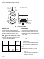
OPERATION
Use Series 61 and 62 Modutrol IV Motors for standard Series
60 operation (drive open, hold, drive closed). Series 62
motors can also be used with the feedback potentiometer as
an input to the controller.
See Table 10 for details on motor response to controller
signals.
NOTE: Reverse the wires at either the motor or control-
ler.
To reverse the rotation direction of a non-spring return motor:
• Reverse the wires at terminals W and B.
Table 10. Modutrol IV Motor Operation.
CHECKOUT
After the installation and linkage adjustment, check the entire
motor and control hookup. Proper checkout ensures that:
• The motor operates the load (damper or valve) properly.
• The motor responds properly to the controller as the input
varies. See Table 10.
• The auxiliary switch, if used, operates at the desired point
of motor rotation.
1. Inspect motor, linkage, and valve or damper to ensure
all mechanical connections are correct and secure.
NOTE: In damper installations, the pushrod should not
extend more than a few inches past the ball
joints.
2. Ensure that there is adequate clearance for the linkage
throughout the entire motor stroke without binding or
striking other objects.
3. Drive the motor fully open and fully closed. See Table
10.
NOTE: Refer to controller or system instructions for
additional checkout procedures.
M62 Checkout
The following procedure will verify that the M62 external
feedback potentiometer is working for a -F or -S model.
• Connect 24 VAC to terminals 3 and 4.
• Connect 5-10 VDC to terminals Y and G (connect +
to Y and - to G).
• Connect either a voltmeter or an oscilloscope to
terminals T and G (connect + to T and - to G).
• Connect terminal R to terminal 1 to drive the motor
towards the fully closed position.
RIGHT/INNER
AUXILIARY
SWITCH
FAST RISE
PORTION
(APPROX.
1 DIFF.)
SLOW RISE
PORTION
(APPROX.
10 DIFF.)
INNER
AUXILIARY
CAM
(BLUE)
NOTE: CAMS ARE OFFSET VERTICALLY TO
PROVIDE BETTER VIEW OF BACK CAM.
FAST RISE
PORTION
(APPROX.
1 DIFF.)
SLOW RISE
PORTION
(APPROX.
10 DIFF.)
MOTOR
OPEN
MOTOR
CLOSE
POWER
END
OUTER
AUXILIARY
CAM
(RED)
LEFT/OUTER
AUXILIARY
SWITCH
M13700
POWER END
OF MOTOR
OUTER AUXILIARY
CAM (RED)
INNER AUXILIARY
CAM (BLUE)
RIGHT/INNER
AUXILIARY SWITCH
LEFT/OUTER
AUXILIARY
SWITCH
MOVE SCREWDRIVER AT
TOP ONLY TO ADJUST CAM.
1/8 INCH
STRAIGHT-BLADE
SCREWDRIVER
Motor Type
Terminal Connection
Resulting
ActionSeries 61 Series 62
Non-Spring Return
or Spring Return
R-W R-1 ccw (closed)
R-B R-2 cw (open)
Non-Spring Return
or Spring Return
R-nothing R-nothing stops driving
Non-Spring Return Power
Failure
Power
Failure
stops (none)
Spring Return Only Upon
Power
Failure
Only Upon
Power
Failure
spring return
(closed)

SERIES 61 AND SERIES 62 MODUTROL IV™ MOTORS
Automation and Control Solutions
Honeywell International Inc.
1985 Douglas Drive North
Golden Valley, MN 55422
customer.honeywell.com
® U.S. Registered Trademark
© 2011 Honeywell International Inc.
63-2629EF—01 M.S. 10-11
Printed in United States
• Connect terminal R to terminal 2 to drive the motor
towards the fully open position.
• Using the voltmeter or the oscilloscope, make sure
the DC voltage is linearly increasing throughout its
entire range.
• The range of Vout for a 90 degree asymmetrical
motor is 5-55% of Vin from closed to open.
• The range of Vout for a 90 degree symmetrical motor
is 25-75% of Vin from closed to open.
• The range of Vout for a 160 degree motor is 5-95% of
Vin from closed to open.
4. For spring return motors, ensure that the valve or
damper returns to its normal position upon power fail-
ure.
5. Return controller to the desired setting before leaving
the job.
REPLACEMENT
Damper Application
1. Turn off power and remove wiring from the old motor.
2. Remove the crank arm from the shaft of the old motor
and remove the old motor.
3. Determine mounting bracket necessity. If the linkage
can reach the new motor shaft position and the crank
arm has clearance for the necessary rotation, the
bracket is not required. Use the 220738A Adapter
Bracket or the 221455A Crank Arm if the crank arm
must rotate through the bottom plane of the motor.
a. If no bracket is required, mount the new motor
directly to the equipment and refer to the
Installation, Settings and Adjustments, and the
Operation and Checkout sections.
b. If the bracket is required, refer to the Adapter
Bracket section and Fig. 3 in addition to the
Installation, Settings and Adjustments, and the
Operation and Checkout sections.
4. Use No. 12 or 1/4 inch machine screws or bolts to
mount the new motor.
5. Mount damper crank arm and linkage to the new motor
shaft.
6. Use the Checkout procedures to test the crank arm and
linkage adjustment.
Valve Application
When replacing a motor in a valve application, the linkage
type determines the necessity for the 220738A Adapter
Bracket. With Q100, Q601 or Q618 Linkages, it is necessary
to use the 220738A to raise the motor shaft to the appropriate
height. Valve applications with a Q5001 Linkage do not
require the 220738A Adapter Bracket. To operate Honeywell
V5011 Two-way or V5013 Three-way Valves through full
stroke, use a 160° stroke motor.

NOTICE TECHNIQUE
Put Bar Code Here
63-2629EF-01
Servomoteurs Modutrol IV
MC
Séries 61 et 62
APPLICATION
Les servomoteurs Modutrol IV
MC
de séries 61 et 62 sont des
appareils trifilaires à régulation flottante, avec ou sans ressort
de rappel. Ils sont destinés à des régulateurs qui assurent la
commutation à sortie flottante, unipolaire et bidirectionnelle de
vannes ou de registres. Les servomoteurs de série 62 sont
équipés d'un potentiomètre d'asservissement électriquement
isolé qui indique la position de l'arbre et peut asservir d'autres
servomoteurs de série 90 ou rééquilibrer un circuit de
commande externe.
CARACTÉRISTIQUES
• Remplacent les servomoteurs M644, M944B, E, G, H, J,
K, R, S et M945B, C, G, K, L, AD.
• Boîte de jonction intégrée assurant une protection
contre les intempéries selon la norme NEMA 3.
• Le ressort de rappel intégré ramène le moteur à la
position normale en cas de coupure de courant.
• Servomoteur et circuit alimentés en courant 24 V c.a. Il
existe des modèles comportant un transformateur
installé en usine et des modèles auxquels on peut
ajouter un transformateur interne sur place.
• Bornes standards à connexion rapide; adaptateur pour
bornes à vis également offert.
• Support d'adaptation permettant d'ajuster la hauteur
de l'arbre des anciens servomoteurs.
• Modèles à course réglable sur place (90
o
à 160
o
).
• Boîtier en aluminium moulé.
• Interrupteurs auxiliaires intégrés (installation en usine)
ou pouvant être ajoutés sur place.
• Durée nominale standard de la course de 30 secondes
à 90
o
et de 60 secondes à 160
o
. Autres durées
également offertes.
• Les servomoteurs à ressort de rappel peuvent
commander des accouplements de vanne du côté
commande ou du côté auxiliaire des arbres dans les
applications de vannes normalement ouvertes ou
normalement fermées.
• Tous les modèles possèdent des arbres doubles
(taraudés et à créneaux à chaque bout).
• Tous les modèles sont équipés de cames
d'interrupteurs auxiliaires.
• Couple uniforme sur toute la plage de tension.
• Servomoteurs conçus pour des vannes et des
registres normalement ouverts ou normalement
fermés.
• Les modèles de série 62 comprennent un
potentiomètre d'asservissement électriquement isolé
qui indique la position de l'arbre.
• Les modèles TRADELINE de série 62 comportent un
potentiomètre d'asservissement linéaire qui peut
asservir des servomoteurs de série 90.

SERVOMOTEURS MODUTROL IV
MC
SÉRIES 61 ET 62
15 63-2629EF—01
CARACTÉRISTIQUES
TECHNIQUES
Modèles : Les modèles TRADELINE® ont été choisis et
emballés pour faciliter le stockage et la manutention et offrir
une valeur de remplacement maximale. Leurs
caractéristiques techniques sont les mêmes que celles des
modèles standards, à moins d'avis contraire.
Guide des numéros de pièce des Modutrol IV :
Voir le Tableau 1.
Encombrement : Voir la Figure 2.
Asservissement : Voir le Tableau 2.
Caractéristiques électriques nominales :
Voir le Tableau 3.
Tableau 11. Guide des numéros de pièce des Modutrol IV.
M Servomoteur
61 Régulation flottante
62 Régulation flottante avec asservissement
8 60 lb-po avec ressort de
rappel
150 lb-po sans ressort de rappel
9 — 300 lb-po sans ressort de rappel
2 Arbre à deux extrémités Normalement fermé à ressort de rappel
4 Sans ressort de rappel
5 Normalement fermé à ressort de rappel
A 0 interr. aux. Course réglable Normalement fermé
B 1 interr. aux.
C 2 interr. aux.
D 0 interr. aux.
E 1 interr. aux.
F 2 interr. aux.
M 61 8 4 A XXXX Voir le catalogue pour le numéro complet du produit
Tableau 12. Caractéristiques de rétroaction Série 62
Numéro de pièce
Résistance de rétroaction (résistance
entre les bornes T, G et Y)
Réglage de la
sensibilité
Rétroaction
linéaire
Résistance de
shunt asserv.
servomoteur
série 90
M6284D1000-S, M6284D1026-S,
M6284D4004-S, M6285A1005-S,
M6285A1054-S, M6285A4009-S
TG = 370-2400-920 Courbe ohm (non
linéaire)
TY = 920-2400-370 Courbe ohm (non
linéaire)
YG = 600 Ohms constant
Non Non 187 Ohm
M6274F1009-F, M6284F1070-F,
M6284F1078-F, M6285F1001-F,
M6294F1009-F, M6294F1017-F,
M6284D1032-F
TG = 0-10K Ohm linéaire
TY = 10-0K Ohm linéaire
YG = 10K Ohms constant
Non Oui Non disponible
M6284A1071-S, M6284A1089-S,
M6284C1028-S
TG = 370-2350-630 Courbe ohm (non
linéaire)
TY = 630-2350-370 Courbe ohm (non
linéaire)
YG = Ohms constants pour une course de
160°,
346 Ohms constants pour une course de
90°.
Oui Non 274 Ohm
M6284A1030-S, M6284A1055-S,
M6284A1097-S, M6284B1004-S,
M6284C1010-S, M6284C1044-S,
M6284F1013-S, M6284F1039-S,
M6285A1039-S, M6285A1047-S,
M6285C1001-S, M6294B1036-S,
M6294D1008-S
TG = 370-2300-550 Courbe ohm (non
linéaire)
TY = 550-2300-370 Courbe ohm (non
linéaire)
YG = 119 Ohms constants pour une course
de 160°,
224 Ohms constants pour une course de
90°.
Oui Non Non nécessaire

SERVOMOTEURS MODUTROL IV
MC
SÉRIES 61 ET 62
63-2629EF—01 16
REMARQUE : Un nombre limité de modèles est disponible en Europe; consultez vos représentants locaux pour les disponibilités.
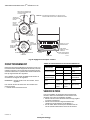
Fig. 15. Course
Tableau 13. Codes de couleurs 50017460-001 primaires.
Tableau 14. Caractéristiques électriques nominales.
Caractéristiques électriques nominales des interrupteurs :
Voir le Tableau 4
Entrées de commande :
Régulation flottante à trois fils (série 60) : ouverture, maintien,
fermeture.
Les modèles de série 62 comprennent un potentiomètre
d'asservissement intégré et électriquement isolé qui
indique la position de l'arbre.
Tableau 15. Caractéristiques électriques nominales des
interrupteurs.
Températures de service nominales :
Maximum : 66°C (150°F) à 25 % du cycle de fonctionnement.
M6284F1062-S TG = 370-2800-1990 Courbe ohm (non
linéaire)
TY = 1990-2800-370 Courbe ohm (non
linéaire)
YG = 1800 Ohms constant
Non Non Non disponible
* Toutes les plages de résistance listées dans la colonne « Résistance de rétroaction » sont pour des moteurs à 160°. Pour un
moteur de 90° la plage sera tronquée ou à la première moitié s'il s'agit d'un moteur asymétrique (par exemple un -F irait de 0 à 5
K) ou à la moitié du milieu s'il s'agit d'un moteur symétrique (par exemple un moteur F irait de 2,5 à 7,5 K).
-S : Rétroaction non-linéaire pour servomoteur Mod IV série 90 à asservissement
-F : Rétroaction 0 à 10 K
-S et -F peuvent tous deux être utilisé comme réducteur de tension. Lorsqu'une tension constante est appliquée à YG, un signal
de tension peut être lu sur TG qui varie de façon linéaire avec une course du moteur de 4 à 96 % de la tension constante
appliquée à YG, pour un moteur de 160° uniquement. Pour un moteur asymétrique de 90° le signal de TG varie de 4 à 56 % et
pour un moteur symétrique de 90° le signal de TG varie de 24 à 76 %. Un signal peut aussi être lu de TY qui est l'opposé du
signal TG.
Tableau 12. Caractéristiques de rétroaction Série 62
Numéro de pièce
Résistance de rétroaction (résistance
entre les bornes T, G et Y)
Réglage de la
sensibilité
Rétroaction
linéaire
Résistance de
shunt asserv.
servomoteur
série 90
COURSE DE 90° COURSE DE 160°
MF31079
LIGNE DE
RÉFÉRENCE
VERTICALE
LIGNE DE
RÉFÉRENCE
VERTICALE
LIGNE DE
RÉFÉRENCE
VERTICALE
LIGNE DE
RÉFÉRENCE
VERTICALE
160
10
90
10
COMPLÈTEMENT
OUVERT
COMPLÈTE-
MENT
OUVERT
COMPLÈTE-
MENT
OUVERT
COMPLÈTE-
MENT
OUVERT
COMPLÈTEMENT
FERMÉ
COMPLÈTEMENT
FERMÉ
COMPLÈTEMENT
FERMÉ
COMPLÈTEMENT
FERMÉ
COURSE DE 90° COURSE DE 160°E
MOTEURS SYMÉTRIQUES MOTEURS SANS RESSORT DE RAPPEL
160
10
90
45
MOTEURS AVEC RESSORTS DE RAPPEL ET SANS RESSORT DE RAPPEL
MOTEURS ASYMÉTRIQUES
MOTEURS SYMÉTRIQUES
Consommation d'énergie
Couleur du fil Tension primaire
Marron 24 V c.a.
Blanc 120 V c.a.
Bleu 230 V c.a.
Noir Commun
Consommation de courant
Numéro de modèle VA nominal
M6184A 15
M6184B 10
M6184D 15
M6184F 15
Caractéristiques
électriques
nominales des
interrupteurs
a
120 V (en
ampères)
240 V (en
ampères)
Pleine charge 7,2 3,6
Rotor bloqué 43,2 21,6
a
Circuit de commande de 40 VA, 120/240 V c.a. à l'interrup-
teur opposé

SERVOMOTEURS MODUTROL IV
MC
SÉRIES 61 ET 62
17 63-2629EF—01
Minimum : -40°C (-40°F).
Poids neutre sur l'arbre (maximum) :
Côté commande ou auxiliaire : 90,8 kg (200 lb).
Charge combinée : 136 kg (300 lb).
Arbre moteur : 9,5 mm (3/8 po) carré.
Course : Modèles à course réglable : réglable sur place de
90° à 160° (Voir la marche à suivre pour le réglage de la
course).
Durée et couple : Voir le Tableau 5.
Durée de vie
60 000 cycles à pleine course
Repositionnements : 1,5 millions
Fig. 16. Encombrement des servomoteurs Modutrol IV de séries 61 et 62 en po (mm).
MF18998C
4-7/8
(124)
5-1/2
(140)
13/16
(20)
4-1/16 (103)
1/4
(7)
1-1/2 (37)
4-1/16 (103)
BOÎTE DE
JONCTION
MOTEUR
CÔTÉ
AUXILIAIRE
CÔTÉ
COMMANDE
SUPPORT
D'ADAPTATION
2-9/16
(66)
5-3/8
(137)
6-7/16
(164)
9/16 (15)
3/4
(19)
VUE DU DESSUS DU SUPPORT VUE DU DESSUS
4-5/8
(116)
4-1/4
(107)
2-5/16
(58)
11/16
(17)
4-7/8 (124)
5-9/16 (141)
1/4 (7)
5-13/16
(148)
1
CÔTÉ COMMANDE
2
3
1-1/2 (37)
3/4
(19)
MODÈLE À RESSORT DE RAPPEL
ILLUSTRÉ
POUR MODÈLES 60 LB-PO À RESSORT DE RAPPEL, 8 ¾ (222);
POUR MODÈLES SANS RESSORT DE RAPPEL, 7 5/16 (185).
POUR MODÈLES 60 LB-PO À RESSORT DE RAPPEL
(MODÈLE ILLUSTRÉ).
POUR MODÈLES SANS RESSORT DE RAPPEL.
1
2
3
13/16
(20)

SERVOMOTEURS MODUTROL IV
MC
SÉRIES 61 ET 62
63-2629EF—01 18
Tableau 16. Durée et couple des servomoteurs Modutrol de série 61 et 62.
REMARQUE : La désignation du couple correspond au cou-
ple nominal à la durée standard de la course
(course nominale de 60 secondes pour 160
o
et
de 30 secondes pour 90
o
à l'exception des ser-
vomoteurs de 34 N.m (300 lb-po) dont la
course dure 2 ou 4 minutes).
IMPORTANT
Il ne faut jamais utiliser le servomoteur au couple de
décollage de façon continue.Potentiomètre d'asser-
vissement (modèles de série 62 seulement):
Modèles TRADELINE (peuvent être shuntés pour
asservir un servomoteur de série 90).
Homologations :
Répertorié Underwriters Laboratories Inc. : n
o
de dossier
E4436, guide n
o
XAPX. (Canada et États-Unis).
En instance de brevet aux États-Unis.
Accessoires :
220736A Jeu d'interrupteur auxiliaire interne; un interrupteur,
peut être installé sur place.
220736B Jeu d'interrupteurs auxiliaires internes; deux inter-
rupteurs, peuvent être installés sur place.
220738A Support d'adaptation servant à augmenter la hau-
teur de l'arbre du servomoteur de 19 mm pour qu'elle cor-
responde à celle des modèles antérieurs de Modutrol.
220741A Adaptateur pour bornes à vis - transforme les
bornes standards à connexion rapide en bornes à vis.
221455A Bras de manivelle réglable à l'infini; il peut faire une
rotation vers le bas et dégager la base du servomoteur
sans qu'il soit nécessaire d'installer un support.
4074ERU Trousse d'étanchéisation, assure une protection
NEMA 3 aux servomoteurs Modutrol IV montés dans une
autre position qu'à la verticale.
50017460-001 Transformateur interne : primaire
24/120/230 V c.a., 50/60 Hz; secondaire 24 V c.a.; bornes
à connexion rapide.
50017460-003 Transformateur interne : primaire 120 V c.a.,
50/60 Hz; secondaire 24 V c.a.; bornes à connexion
rapide.
7617ADW Bras de manivelle, il peut faire une rotation vers le
bas et dégager la base du servomoteur sans qu'il soit
nécessaire d'installer un support d'adaptation.
Q100 Accouplement servant à raccorder un servomoteur
Modutrol à une vanne papillon V51. Nécessite un support
d'adaptation 220738A.
Q181 Potentiomètre auxiliaire pour la commande en
séquence ou en parallèle de 1 à 4 servomoteurs modu-
lants additionnels (série 90).
Q5001 Ensemble support et accouplement servant à rac-
corder un servomoteur Modutrol IV à une vanne à eau ou à
vapeur.
Q605 Accouplement de registre; raccorde un servomoteur à
un registre; comprend le bras de manivelle du servomo-
teur.
Q607 Interrupteur auxiliaire externe - commande l'équipement
auxiliaire en fonction de la position du servomoteur.
ES650-117 Le boîtier antidéflagrant protège le moteur dans
les atmosphères explosives. Ne convient pas au Q5001
(ou à tout autre accouplement de vanne). Commander
séparément auprès de EGS Enclosures. Pour commander,
prière de s'adresser à : EGS Enclosures, (281) 774-3763;
ou communiquer par écrit avec :
EGS Enclosures de Houston, au Texas
Karen Barfield 281-774-3763
http://appletonelec.com/
Numéro de pièce ES-650-117
Il faut obtenir un ensemble d'accouplement 7617DM de
Honeywell qui sera utilisé avec le couvercle.
INSTALLATION
AVANT D'INSTALLER CET APPAREIL…
7. Lire attentivement les présentes instructions. Le fait de
ne pas les suivre risque d'endommager le produit ou de
constituer un danger
Durée nominale
a
en sec
Couple nominal en N.m (lb-po)
b
Couple normal de service Couple de décollage
c
Course de
90
o
Course de
160
o
Avec ressort de
rappel
Sans ressort de
rappel
Avec ressort de
rappel
Sans ressort de
rappel
15 30 — 8,5 (75) — 17,0 (150)
30 60 6,8 (60) 4,0 (35) 13,6 (120) 7,9 (70)
17,0 (150) 34,0 (300)
60 120 34,0 (300) 68,0 (600)
120 240 —
—17,0 (150) 34,0 (300)
a
La durée de la course est la même pour tous les modèles TRADELINE. Certains modèles pour fabricants sont offerts avec
durée
et couple non standards
.
b
Le couple des modèles à arbre aux deux extrémités correspond à la somme des couples de l'arbre (couple côté commande et
couple côté auxiliaire).
c
Le couple de décollage est le couple maximum possible servant à surmonter les charges importantes et occasionnelles qui se
produisent par exemple lorsque le registre ou la vanne est coincé.

SERVOMOTEURS MODUTROL IV
MC
SÉRIES 61 ET 62
19 63-2629EF—01
8. Vérifier les caractéristiques spécifiées dans les instruc-
tions et indiquées sur le produit, et s'assurer que celui-ci
correspond à l'application prévue.
9. L'installateur doit être un technicien d'expérience ayant
reçu une formation pertinente.
10. Après l'installation, vérifier le fonctionnement du produit
comme indiqué aux présentes instructions.
CAUTION
Risque de choc électrique et de dommage matériel
Peut donner un choc électrique ou court-circuiter
le circuit du matériel.
Couper toute alimentation électrique avant de
procéder à l'installation.
Les servomoteurs comportant des interrupteurs
auxiliaires peuvent avoir plus d'un dispositif de
coupure.
CAUTION
Risque de dommage matériel.Peut endommager le
servomoteur au point de le rendre inutilisable.
Ne jamais faire tourner l'arbre du servomoteur à la
main ou à l'aide d'une clé.
Faire tourner de force l'arbre du servomoteur
endommage le train d'engrenages et les interrupteurs
de fin de course.
IMPORTANT
Il faut toujours effectuer une vérification complète
une fois l'installation terminée.
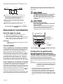
Emplacement
Choisir un emplacement offrant suffisamment d'espace de
dégagement pour l'installation des accessoires et pour
l'entretien du servomoteur (voir la Fig. 2). Si le servomoteur
doit être installé à l'extérieur, utiliser des raccords de conduit
étanches aux liquides avec la boîte de jonction pour assurer
une protection anti-intempéries NEMA 3. Si le servomoteur
doit être installé à l'extérieur autrement qu'à la verticale,
installer une trousse d'étanchéisation 4074ERU et des
raccords étanches aux liquides pour procurer une protection
NEMA 3.
CAUTION
Risque de dommage au servomoteur.
Les vapeurs corrosives et acides peuvent endommager les
pièces métalliques.
Installer le servomoteur dans un endroit où on ne retrouve pas
de vapeurs acides et autres vapeurs corrosives.
Dans les atmosphères très salines, la plaque de montage et
les vis devraient être plaquées au zinc ou au cadmium et non
en acier inoxydable ou en laiton. Utiliser le support
d'adaptation 220738A pour l'installation dans de telles
conditions.
Montage
Respecter les directives suivantes pour que le servomoteur
soit correctement installé :
• Toujours installer le servomoteur de façon à ce que l'arbre
de manivelle soit à l'horizontale.
• Les brides de fixation qui font saillie à la base du boîtier du
servomoteur sont percées pour recevoir des vis à métal ou
des boulons de 6,4 mm (1/4 po).
• Les servomoteurs sans ressort de rappel sont expédiés de
l'usine en position fermée (à la limite de la rotation dans le
sens antihoraire, vu du côté commande du servomoteur).
Support d'adaptation
Le support d'adaptation 220738A, placé entre le servomoteur
et le matériel, augmente la hauteur de l'arbre du servomoteur
de 19 mm (0,75 po) pour qu'elle corresponde à celle des
modèles antérieurs de servomoteurs Modutrol.
Le support d'adaptation doit être installé dans les applications
suivantes:
• Interrupteur auxiliaire externe Q607
• Les applications d'accouplement de registre exigent un
dégagement supplémentaire pour :
— La rotation du bras de manivelle jusqu'à la position
vers le bas.
— Permettre à l'accouplement de registre d'atteindre
l'arbre du servomoteur
• Tous les accouplements de vanne sauf le Q5001
REMARQUE : Lorsque le support n'est pas utilisé dans une
installation de rechange, il faut ajuster l'accou-
plement de registre pour qu'il corresponde à la
nouvelle position du registre.
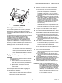
Pour installer le servomoteur avec le support :
1. Fixer le support au matériel en utilisant des boulons
standards ou ceux qui sont déjà en place.
2. À l'aide des boulons fournis, fixer le servomoteur aux
ouvertures filetées du support. Voir la Fig. 3.
Installations avec accouplement de vanne (sauf le Q5001) :
1. Fixer le support sur l'accouplement
2. Placer le servomoteur sur le support et aligner l'arbre
avec l'accouplement
3. Fixer le servomoteur au support avec les quatre bou-
lons fournis. Voir la Fig. 4.

SERVOMOTEURS MODUTROL IV
MC
SÉRIES 61 ET 62
63-2629EF—01 20
Fig. 17. Installation du servomoteur sur un support d'adaptation.
Fig. 18. Fixation du servomoteur à un accouplement de
vanne Q5001.
Accouplements de registre
Le servomoteur ne comporte pas d'arbre de manivelle. Il faut
commander séparément le bras de manivelle (voir
Accessoires dans la section des caractéristiques techniques).
Pour des instructions détaillées sur les accouplements
particuliers, consulter les directives d'installation qui
accompagnent chaque accouplement.
CAUTION
Risque de dommage matériel. Bloquer un
servomoteur peut endommager l'arbre.
S'assurer que l'installation des servomoteurs et des
accouplements permet au servomoteur de parcourir
sa course complète sans obstruction.
Accouplement de vannes
Le support d'adaptation 220738A doit être utilisé avec
l'accouplement Q100 dans toutes les applications de vannes.
Le support d'adaptation n'est pas nécessaire avec
l'accouplement de vanne Q5001 (voir la Fig. 4).
Boîte de jonction
Utilisée avec des raccords de conduits étanches aux liquides,
la boîte de jonction procure au servomoteur une protection
contre les intempéries NEMA 3. La boîte de jonction, pièce
fournie avec les servomoteurs de remplacement, comprend
des ouvertures défonçables pour faire passer les conduits et
des bornes. Il faut utiliser une boîte électrique pour loger un
transformateur interne ou des interrupteurs auxiliaires
internes.
MF18999
BASE DE
L’APPAREIL
SUPPORT
D’ADAPTATION
BOULONS
STANDARDS (4)
MOTEUR
BOULONS
FOURNIS (4)
BOÎTE DE
JONCTION
SANS RESSORT DE RAPPEL
AVEC RESSORT DE RAPPEL
1 VIS À MÉTAL OU BOULONS ZINGUÉS Nº 12 OU ¼ PO
1
POWER
END
POWER
END
POW
ER
END
BOULONS DE
MONTAGE
1/4-20 UNC 1 PO
LONGUEUR
Q5001
ACCOUPLEMENT
DE VANNE
MF18994
MOTEUR
BOÎTE DE
JONCTION
CÔTÉ
COMMANDE
DU MOTEUR
VANNE
La page charge ...
La page charge ...
La page charge ...
La page charge ...
La page charge ...
La page charge ...
La page charge ...
La page charge ...
-
 1
1
-
 2
2
-
 3
3
-
 4
4
-
 5
5
-
 6
6
-
 7
7
-
 8
8
-
 9
9
-
 10
10
-
 11
11
-
 12
12
-
 13
13
-
 14
14
-
 15
15
-
 16
16
-
 17
17
-
 18
18
-
 19
19
-
 20
20
-
 21
21
-
 22
22
-
 23
23
-
 24
24
-
 25
25
-
 26
26
-
 27
27
-
 28
28


Honeywell Modutrol IV M6294F1009-F Information produit
- Taper
- Information produit
dans d''autres langues
Documents connexes
-
Honeywell Servomoteurs Modutrol IV Série 90 Mode d'emploi
-
-
-
Honeywell MN6105VAV Installation Instructions Manual
-
-
-
-
Autres documents
-
 Suncourt ZC206 Guide d'installation
-
Bernard Controls SQX Range INTELLI+ Installation & Operation Manual
-
AUMA Multi-turn actuators SAEx 25.1 Mode d'emploi
-
ESAB iCNC Performance CNC Controller Manuel utilisateur
-
Miller LA069205 Le manuel du propriétaire
-
Hobart Welding Products CONTRACTOR 40G Manuel utilisateur
-
-
-
Genie GCL Fire Door Operator / Installation Manual
-
Lincoln Electric Weldanpower 250 Mode d'emploi
