Federal Signal 350 Vibratone® Horn Manuel utilisateur
- Taper
- Manuel utilisateur

MODEL 350
Vibratone® Electro-Mechanical Horn
Installation and Maintenance
Instructions
Limited Warranty: This product’s limited warranty can
be found at www.fedsig.com/SSG-Warranty.
Messages to Installers and Users This product
should be installed to code by a licensed electrician
and follow all safety instructions. Failure to do so may
result in property damage, serious injury, or death.
• Read and understand instructions before
installing or operating the equipment.
• SHOCK HAZARD - To avoid electrical shock
hazards, do not connect wires when power is
applied.
• Optimum sound distribution will be severely
reduced if any objects are in front of the horn.
Ensure that the front of the horn is clear of any
obstructions.
• All effective warning sounders produce loud
sounds that may cause, in certain situations,
permanent hearing loss. Take appropriate
precautions, such as hearing protection. The
device should be installed far enough away from
potential listeners to limit their exposure while
still maintaining its effectiveness. The OSHA
Code of Federal Regulations 1910.95 Noise
Standard provides guidelines that may be used
regarding permissible noise exposure levels.
• After installation, test the system to ensure that it
is operating properly.
Overview: The Model 350 horn is a very loud electro-
mechanical device that produces a horn tone by
vibration of a diaphragm. This horn is capable of
reproducing coded blasts or sustained tone. The horn
has a duty cycle of ve minutes on, ve minutes off.
Unpacking the Device: After unpacking the device,
examine it for damage and verify the parts. See Table
1 for the Carton Contents List. If a part is missing or
appears damaged, do not attempt to install. Contact
Federal Signal Customer Support at +1 708-587-3587
Table 1 Carton Contents List
Qty Description
1 350 Horn
2 8-32 x 1-5/8" oval head screws
2 10-32 x 5/8" oval head tapping screws
1 10-32 x 3/8" hex head tapping screw
1 10-32 x 3/8" hex socket head set screw
Mounting the Device
The horn may be directly mounted to a standard 4-inch
square electrical box or may be mounted using various
FederalSignal accessories (purchased separately).
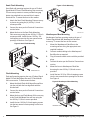
Outlet Box Mounting
To mount the horn to a wall or other at vertical
surface:
1. Mount a 4-inch square electrical box to the
mounting surface with appropriate user supplied
hardware.
2. Connect the wires per the Electrical Connections
section below.
3. Mount the horn to the box using the two 8-32 by
1-5/8-inch screws provided.
4. Install the two 10-32 by 5/8-inch tapping screws
into the two unused screw openings on the horn.
See Figure 1.
Figure 1 Outlet Box Mounting
290A2450-02
NB
256918 Rev K3 0323

2Federal Signal signaling.fedsig.com
Semi-Flush Mounting
Semi-ush wall mounting requires the use of Federal
Signal Model SF Semi-Flush Mounting Plate accessory.
This accessory mounts to a user-provided two-gang
plaster ring attached to a recessed 4-inch square
electrical box. To mount the horn in this manner:
1. Attach the Semi-Flush Mounting Plate accessory
to plaster ring using the (4) 6-32 by 1/4-inch
screws provided.
2. Connect the wires per the Electrical Connections
section below.
3. Mount the horn to the Semi-Flush Mounting
Plate accessory using the two 8-32 by 1-5/8-inch
screws provided. Install the two 10-32 by 5/8-
inch tapping screws into the two unused screw
openings on the horn. See Figure 2.
Figure 2 Semi-Flush Mounting
290A2450-04
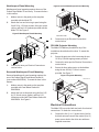
Flush Mounting
Flush wall mounting requires the use of Federal Signal
Model FB Flush Wall Mount Box and FG Flush Mount
Grille accessories. To ush mount the horn:
1. Mount the Model Flush Wall Mount Box wall box
into the wall with the box edge ush with the
nished wall.
2. Connect the wires per the Electrical Connections
section below.
3. Mount the horn and Flush Mount Grille accessory
to the Flush Wall Mount Box wall box using the
two 8-32 by 1-5/8-inch screws provided.
4. Install the two 10-32 by 5/8-inch tapping screws
into the two unused screw openings on the horn.
See Figure 3.
Figure 3 Flush Mounting
290A2450-08
FB
FG
Weatherproof Box Mounting
Weatherproof surface mounting requires the use of
Federal Signal Model WB Weatherproof Back Box
accessory. To mount the horn in this manner:
1. Mount the Weatherproof Back Box to the
mounting surface using the appropriate user-
supplied hardware.
2. Connect conduit/cabling to the Weatherproof
Back Box box as required.
3. Plug all unused conduit entries with the provided
plugs.
4. Connect the wires per the Electrical Connections
section.
5. Mount the horn to Weatherproof Back Box
box using the two 8-32 by 1-5/8-inch screws
provided.
6. Install the two 10-32 by 5/8-inch tapping screws
into the two unused screw openings on the horn.
See Figure 4.
Figure 4 Weatherproof Box Mounting
290A2450-03C

3
Federal Signal signaling.fedsig.com
Weatherproof Panel Mounting
Weatherproof panel mounting requires the use of the
Federal Signal Model TR accessory. To mount the horn
in this manner:
1. Make a cutout in the panel per the template
provided with the Model TR.
2. Attach the horn and trim ring to panel using the
four 8-32 by 1-5/8-inch screws, four nylon screw
collars, and four8-32 locknuts provided with the
Model TR. See Figure 5.
Figure 5 Weatherproof Panel Mounting
3. Connect the wires per Electrical Connections
section below.
Recessed Weatherproof Panel Mounting
Recessed weatherproof panel mounting requires the
use of the Federal Signal Panel Mount Gasket Kit
(part number K8435666A). To mount the horn in this
manner:
1. Make a cutout in the panel per the template
provided with Panel Mount Gasket Kit
K8435666A.
2. Attach the horn to the panel using the four 8-32
by 1-5/8-inch screws, gasket, and four 8-32
locknuts provided with Panel Mount Gasket Kit
K8435666A. See Figure 6.
Figure 6 Recessed Weatherproof Panel Mounting
290A2602-03B
3. Connect wires per Electrical Connections
section below.
PR2-NM Projector Mounting
The Model PR2-NM may be added to any of the
installations described on this sheet. To mount the
projector:
1. Secure the projector to the horn using the two
10-32 by 5/8-inch tapping screws provided.
2. Connect the wires per the Electrical Connections
section below.
3. Secure the horn and projector to the backbox
using the two 8-32 by 1-5/8-inch screws
provided. See Figure 7.
Figure 7 Projector Mounting
PR2
290A2450-06
Electrical Connections
The Model 350 is provided with two leads for electrical
connections.
To make the connections:
1. Connect the line (L or L1) power source lead to
the black wire and connect the neutral (N or L2)
power source lead to the white wire with user-
supplied connectors.

2. Connect the ground to the green ground screw
if required.
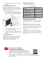
Optional Volume Control
The 350 horn is shipped with the volume set for
maximum sound output. However, you can reduce the
sound level with the provided 10-32 hex socket head
set screw. To adjust the volume:
1. Before installing the set screw, thread the
provided 10-32 hex head tapping screw into the
hole on the front of the horn shown in Figure 8.
Figure 8
290A7445
ALLEN-HEAD ADJUSTMENT SCREW:
For softer sound, turn clockwise
Tornillo de ajuste con cabeza allen
(para un nivel de sonido más suave, gire
en sentido horario)
Vis de réglage à tête allen (pour un niveau
sonore plus faible, tournez dans le sens des
aiguilles d'une montre)
SOUND HAZARD: Wear hearing protection when
working with this horn.
PELIGRO DE SONIDO: Lleve protección auditiva
cuando trabaje con la bocina.
DANGER DU SON : P
orter une protection auditive
lors de l’utilisation le klaxon.
2. Remove the tapping screw, and then thread the
set screw into the threaded hole.
3. Use a 3/32-inch hex key wrench to rotate the set
screw clockwise until the desired sound level is
reached.
Testing/Operating
After installation, test the system to verify that each
signal operates. Establish a program for periodic
testing of the device. Provide a copy of these
instructions to all operating personnel.
Ordering Accessories
See Table 2 for available accessories.
Table 2 Accessories
Description Model/Part Number
Semi-Flush Mounting Plate SF
Flush Wall Mount Box FB
Flush Mount Grille FG
Weatherproof Back Box WB
Panel Mount Trim Ring TR
Panel Mount Gasket Kit K835666A
Double Projector PR2-NM
Maintenance and Service
Technical Assistance: Contact our Technical Support
Team at +1 708-587-3587 or signalsupport@fedsig.
com.
Repair Service: A return authorization is required.
Contact your Authorized Distributor or Federal Signal
Customer Support. Defective products under warranty
will be repaired or replaced at Federal Signal’s
discretion.
Product Returns: Returns require authorization from
Federal Signal. Contact your Authorized Distributor for
more information on our return policy or to request a
return.
2645 Federal Signal Drive, University Park, Illinois 60484
Additional translations available at signaling.fedsig.com
Traducciones adicionales disponibles en signaling.fedsig.com
Customer Support 1-800-344-4634+1-708-534-4756, [email protected]
Technical Support 1-800-755-7621+1-708-587-3587, [email protected]
signaling.fedsig.com
-
 1
1
-
 2
2
-
 3
3
-
 4
4


Federal Signal 350 Vibratone® Horn Manuel utilisateur
- Taper
- Manuel utilisateur
dans d''autres langues
Documents connexes


Autres documents
-
Crown CTs 600 Manuel utilisateur
-
EDWARDS 867, 868 & 869 Guide d'installation
-
 Hangar 9 HAN4770 Le manuel du propriétaire
-
E-flite ALBATROS D.Va 25e Manuel utilisateur
-
E-flite Beast 60e ARF Manuel utilisateur
-
Genie GCL Fire Door Operator / Installation Manual
-
-
Hangar 9 HAN5015 Le manuel du propriétaire
-
Eaton 9395C-1100/1100 Mode d'emploi
-
Harris XL-185M Guide d'installation
