Faber MIRROR BK BRS X/V A90 LOGIC Le manuel du propriétaire
- Catégorie
- Hottes
- Taper
- Le manuel du propriétaire

Instructions Manual
Manuel d’Instructions
Bedienungsanleitung
Manual de instrucciones
Εγχειρίδιο οδηγιών
Руководство по эксплуатации
Felhasználói Kézikönyv

2
2
INDEX
SAFETY INFORMATION ......................................................................................................................................................... 4
CHARACTERISTICS ............................................................................................................................................................. 7
INSTALLATION ...................................................................................................................................................................... 9
USE ...................................................................................................................................................................................... 12
CARE AND CLEANING ......................................................................................................................................................... 14
SOMMAIRE
CONSIGNES DE SÉCURITÉ............................................................................................................................................ 16
CARACTERISTIQUES ......................................................................................................................................................... 19
INSTALLATION .................................................................................................................................................................... 21
UTILISATION ....................................................................................................................................................................... 24
NETTOYAGE ET ENTRETIEN .............................................................................................................................................. 26
INHALTSVERZEICHNIS
SICHERHEITSINFORMATIONEN ......................................................................................................................................... 28
CHARAKTERISTIKEN ......................................................................................................................................................... 31
MONTAGE ........................................................................................................................................................................... 33
BEDIENUNG ........................................................................................................................................................................ 36
REINIGUNG UND WARTUNG ............................................................................................................................................... 38
ÍNDICE
INFORMACIÓN DE SEGURIDAD .......................................................................................................................................... 40
CARACTERÍSTICAS ........................................................................................................................................................... 43
INSTALACIÓN ..................................................................................................................................................................... 45
USO ...................................................................................................................................................................................... 48
LIMPIEZA Y MANTENIMIENTO ............................................................................................................................................. 50
ΠΕΡΙΕΧΟΜΕΝΑ
ΣΥΜΒΟΥΛΕΣ ΚΑΙ ΣΥΣΤΑΣΕΙΣ ............................................................................................................................................ 52
ΧΑΡΑΚΤΗΡΙΣΤΙΚΑ ............................................................................................................................................................... 55
ΕΓΚΑΤΑΣΤΑΣΗ .................................................................................................................................................................... 57
ΧΡΗΣΗ ................................................................................................................................................................................. 60
ΚΑΘΑΡΙΣΜΟΣ ΚΑΙ ΣΥΝΤΗΡΗΣΗ ........................................................................................................................................... 62
УКАЗАТЕЛЬ
ИНФОРМАЦИЯ ПО БЕЗОПАСНОСТИ ................................................................................................................................ 64
ХАРАКТЕРИСТИКИ ............................................................................................................................................................ 67
УСТАНОВКА ........................................................................................................................................................................ 69
ЭКСПЛУАТАЦИЯ ................................................................................................................................................................ 72
ОЧИСТКА И ОБСЛУЖИВАНИЕ ........................................................................................................................................... 74
EN
FR
DE
ES
GR
RU

3
3
TÁRGYMUTATÓ
BIZTONSÁGI INFORMÁCIÓK ............................................................................................................................................... 76
JELLEMZŐK ........................................................................................................................................................................ 79
FELSZERELÉS .................................................................................................................................................................... 81
HASZNÁLAT ........................................................................................................................................................................ 84
ÁPOLÁS ÉS KARBANTARTÁS ............................................................................................................................................. 86
.............................................................................................................................. 88
...................................................................................................................................................... 91
........................................................................................................................................................ 93
........................................................................................................................................................ 96
!" ......................................................................................................................................... 98
HU
SA

EN
4
4
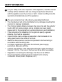
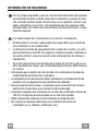
SAFETY INFORMATION
For your safety and correct operation of the appliance, read this manual
carefully before installation and use. Always keep these instructions
with the appliance even if you move or sell it. Users must fully know the
operation and safety features of the appliance.
The wire connection has to be done by specialized technician.
• The manufacturer will not be held liable for any damages resulting from
incorrect or improper installation.
• The minimum safety distance between the cooker top and the extractor
hood is 650 mm (some models can be installed at a lower height,
please refer to the paragraphs on working dimensions and installation).
• If the instructions for installation for the gas hob
specify a greater
distance, this must be respected.
• Check that the mains voltage corresponds to that indicated on the
rating plate fixed to the inside of the hood.
• Means for disconnection must be incorporated in the fixed wiring in
accordance with the wiring rules.
• For Class I appliances, check that the domestic power supply
guarantees adequate earthing.
• Connect the extractor to the exhaust flue through a pipe of minimum
diameter 120 mm. The route of the flue must be as short as possible.
• Regulations concerning the discharge of air have to be fulfilled.
• Do not connect the extractor hood to exhaust ducts carrying
combustion fumes (boilers, fireplaces, etc.).

EN
5
5
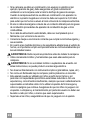
•
If the extractor is used in conjunction with non-electrical appliances
(e.g. gas burning appliances), a sufficient degree of aeration must be
guaranteed in the room in order to prevent the backflow of exhaust gas.
When the cooker hood is used in conjunction with appliances supplied
with energy other than electric, the negative pressure in the room must
not exceed 0,04 mbar to prevent fumes being drawn back into the room
by the cooker hood.
• The air must not be discharged into a flue that is used for exhausting
fumes from appliances burning gas or other fuels.
• If the supply cord is damaged, it must be replaced from the manufac-
turer or its service agent.
• Connect the plug to a socket complying with current regulations, locat-
ed in an accessible place.
• With regards to the technical and safety measures to
be adopted for
fume discharging it is important to closely follow the regulations provid-
ed by the local authorities.
WARNING: Before installing the Hood, remove the protective films.
• Use only screws and small parts in support of the hood.
WARNING: Failure to install the screws or fixing device in accordance
with these instructions may result in electrical hazards.
• Do not look directly at the light through optical devices (binoculars,
magnifying glasses…).
• Do not flambè under the range hood; risk of fire.
• This appliance can be used by children aged from 8 years and above
and persons with reduced physical, sensory or mental capabilities or
lack of experience and knowledge if they have been given supervision
or instruction concerning use of the appliance in a safe way and under-
stand the hazards involved. Children shall not play with the appliance.
Cleaning and user maintenance shall not be made by children without
supervision.
• Children should be supervised to ensure that they do
not play with the
appliance.

EN
6
6
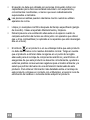
•
The appliance is not to be used by persons (including children) with re-
duced physical, sensory or mental capabilities, or lack of experience
and knowledge, unless they have been given supervision or instruction.
Accessible parts may become hot when used with cooking appliances.
• Clean and/or replace the Filters after the specified time period (Fire
hazard). See paragraph Care and Cleaning.
• There shall be adequate ventilation of the room when the range hood is
used at the same time as appliances burning gas or other fuels (not
applicable to appliances that only discharge the air back into the room).
• The symbol on the product or on its packaging indicates that this
product may not be treated as household waste. Instead it shall be
handed over to the applicable collection point for the recycling of elec-
trical and electronic equipment. By ensuring this product is disposed of
correctly, you will help prevent potential negative consequences for the
environment and human health, which could otherwise be caused by
inappropriate waste handling of this product. For more detailed infor-
mation about recycling of this product, please contact your local city of-
fice, your household waste disposal service or the shop where you pur-
chased the product.

EN
7
7
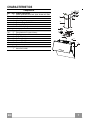
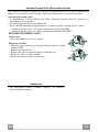
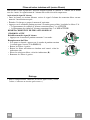
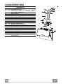
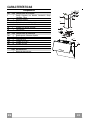
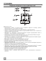
CHARACTERISTICS
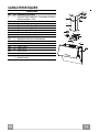
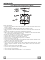
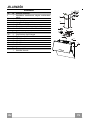
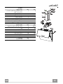
Components
Ref. Q.ty Product components
1 1 Cooker hood with control unit, lights, blower unit, filters
2.1 1 Upper chimney
2.2 1 Lower chimney
8 1 Air outlet grid
9 1 Reducer flange Ø 150-120
10 1 Damper (Optional)
16 1 Cover for recycling version
Ref. Q.ty Installation components
7.2.1 2 Fixing brackets for upper chimney
11 5 Plugs
11a 2 Plugs SB 12/10
12a 5 Screws 4,2 x 44,4
12c 10 Screws 2,9 x 6,5
12e 2 Screws 2,9 x 9,5
Q.ty Documentation
1 Instruction booklet
2.1
2.2
12c
12a
7.2.1 11
11
12a
10
9
1
16
12c
12d
8
11a

EN
8
8
Dimensions
The dimensions depend on the chosen version
50
649
MIN 530 MAX 990
463
339
800
749
500
91
898
570
300
200
50
649
MIN 330 MAX 590
463
339
800
749
300
91
898
570
300
200

EN
9
9
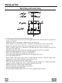
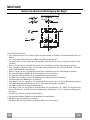
INSTALLATION
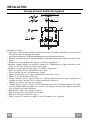
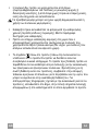
Wall drilling and bracket fixing
11a
1
1
11
12a
11
12a
2
2
249 249
960
X
1÷2
7.2.1
368
210 210
458
As a first step, proceed with the following drawings:
• a vertical line up to the ceiling or up to the upper limit, at the centre of the area in which the
hood is to be fitted;
• a horizontal line at a minimum 960 mm above the cooker top.
• Mark a point (1) on the horizontal line, 249 mm to the right of the vertical reference line.
• Repeat this operation on the other side, checking that the two marks are levelled.
• Mark a reference point (2) as indicated at 210 mm from the vertical reference line and 458
mm above the cooker top.
• Repeat this operation on the other side, checking that the two marks are levelled.
• Drill at the marked points (1), using a ø 12 mm drill bit.
• Drill at the marked point (2), using a ø 8 mm drill bit.
• Insert the bracket plugs 11a into the holes (1) and tighten the screws.
• Insert plug 11 into hole (2).
• Place bracket 7.2.1 on the wall, about 1-2 mm from the ceiling or from the upper limit,
aligning the centre (notch) with the vertical reference line.
• Mark the wall at the centres of the bracket holes.
• Place the bracket 7.2.1 on the wall at X mm below the first bracket (X = height of the upper
chimney section), aligning the centre (notch) with the vertical line.
• Mark the wall at the centres of the bracket holes.
• Drill ø 8 mm holes at all the marked centre points.
• Insert the wall plugs 11 in the holes.
• Fix the brackets using the 12a screws (4,2 x 44,4) supplied with the hood.

EN
1
0
10
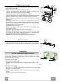
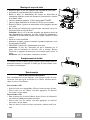
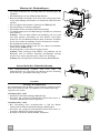
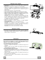
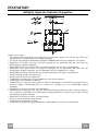
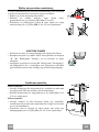
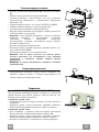
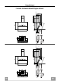
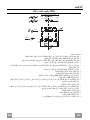
Fitting the Hood canopy
• Adjust the two screws Vr, in the brackets 11a,
so that they are at the
start of their travel (B).
• Hook the hood body to the two brackets 11a.
• Connect the Hood to the Mains Power Supply, inser
ting a bipolar
switch with a contact aperture of at least 3mm.
• Open the top panel. (See the paragraph on USE)
•
Open the Bottom Door by pulling it downwards with your hands.
• Remove the Metal Grease Filters using the handles provided.
• From the inside of the hood body, turn screws Vr
to level the hood
body itself.
Warning
: should the rear wall not be completely flat and cause
the two glass panels not to be aligned, pls turn on the two knobs in
the lower part inside the hood body until you reach the per
alignment of the two glass panels.
• Fasten the safety screw 11.
•
Replace the Metal Grease Filters, then shut the top panel. (See the
paragraph on USE)
• Disconnect the hood from the mains power supply.
Warning: Should the door encounter an obstacle
while opening
or closing it will block. When the obstacle is removed and the
button is pressed again the door will open.
Warning: In the event of a malfunction, check the fuse.
(B)
11a
Vr
11
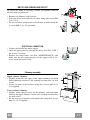
Replacing the fuser
• The fuser is placed up on the left side. Turn the fuser holder
as
indicated. Replace the fuser with one having the same features.
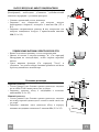
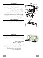
Connections
DUCTED VERSION AIR EXHAUST SYSTEM
When installing the ducted version, connect the hood to the chim
using either a flexible or rigid pipe ø 150 or 120mm, the choice
of
which is left to the installer.
To install a ø 150 pipe
• To install the dumper 10
• Fix the pipe in position using sufficient pipe clamps (not s
u
plied).
To install a ø 120 pipe
• To install a ø 120 mm air exhaust connection, insert the redu
cer
flange 9 on the dumper 10.
• Fix the pipe in position using sufficient pipe clamps (not s
u
plied).
•
Remove any activated charcoal filters.
ø 120
ø 150
10
10
9

EN
1
1
11
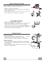
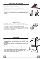
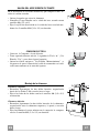
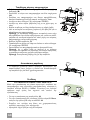
RECYCLING VERSION AIR OUTLET
To install the hood in recycling version, the optional charcoal
filter kit must be purchased.
• Remove the chimney angle bracket.
• Screw the filter cover onto the air outlet, using four screws 12c
(2.9 x 12.5).
• Fix the air outlet grid 8 on the recirculation air outlet using the
2 screws 12d (2,9 x 9,5) provided.
16
12c
12d
8
ELECTRICAL CONNECTION
• Connect the hood to the mains supply.
• Open the upper panel by pressing the A-key (See Part “USE” )
for at least 2 seconds.
• Remove the metal filters (See Part “MAINTENANCE”) and
make sure that the connector piece of the supply cable is cor-
rectly inside the hood socket.
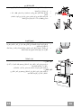
Chimney assembly
Upper exhaust Chimney
• Slightly widen the two sides of the upper chimney and hook
them behind the brackets 7.2.1, making sure that they are well
seated.
• Secure the sides to the brackets using the 4 screws 12c (2,9 x
9,5) supplied.
Lower exhaust Chimney
• Slightly widen the two sides of the chimney and hook them
between the upper chimney and the wall, making sure that they
are well seated.
• Fix the lower part laterally to the hood body using the 2 screws
12c (2,9 x 9,5) supplied.
12c
2.1
2.2
2
7.2.1
12c

EN
1
2
12
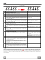
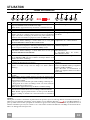
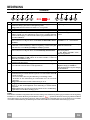
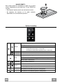
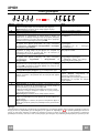
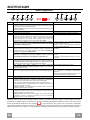
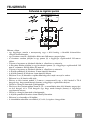
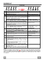
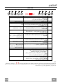
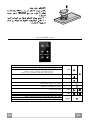
USE
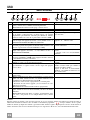
Control panel
Bu
t
ton
Function
Display
A
Door Closed
: Press and hold for approximately 2 Seconds to open the door and
turn the motor on at the last speed set.
Door Open: Press briefly to turn the motor Off or On.
Displays the set speed.
B
Decreases the working speed. The number of lighted segments decreases.
C
Increases the working speed. The number of lighted segments increases.
D
Activates/Deactivates Intensive speed
. This speed is timed to run for 10
minutes. At the end of this time the system will automatically return to the speed
set before. Suitable to deal with maximum levels of cooking fumes. Cannot be
activated when in 24H mode.
The indicator I flashes and all the segments on
the Display are lit.
Press and hold the button for approximately 5 seconds, with all the loads turned
off (Motor and Lights) and no alarms in progress, to turn the Activated
Charcoal Filter Alarm On / Off.
Button "
C
" flashes twice – Alarm On.
Button "C " flashes once – Alarm Off.
E
Activates/Deactivates 24H speed
. This starts the motor at a speed that allows
suction of 100 m3/h for 10 minutes every hour. This mode cannot be activated
if Intensive or Delay modes are active.
Displays 24 and the segments on the Display
light up in cycle.
Press and hold the button for approximately 5 seconds, with all the loads turned
off (Motor and Lights) and no alarms triggered, to turn the Remote control On
/ Off.
(Motor LED bar flashes twice) - Remote control
On.
(Motor LED bar flashes once) - Remote control
Off.
F
Activate / Deactivate Delay
. Can be activated with motor on (except for
Intensive and 24H mode). Activates automatic shutdown of the Motor and the
Lighting with a 30’ delay.
Displays a Clock symbol.
Press and hold for 5 Seconds to
Activate / Deactivate Lock Keyboard mode
for example in order to clean the Glass.
The Leds light up and run a start-up sequence.
G
Performs a Reset of the Filter saturation alarm when the button is pressed for
approximately 3 seconds when all the users (motor + lights) are turned off
After 100 hours in operation the
Drop
symbol is
displayed to indicate saturation of the Metal
Grease Filters.
After 200 hours in operation the letter C is
displayed to indicate saturation of the Activated
Charcoal filters.
H
Modifies the intensity of the Lighting each time the Button is pressed, in cycle.
-
I
Door Closed
: When pressed and held for approximately 2 seconds opens the
door half way and turns the lighting on to maximum intensity. The intensity can
be modified using button H.
- When the button is pressed again, the lighting turns off and the door closes.
- When button A is pressed, the Lights turn off and the motor only works at the
first two speeds.
Door Open
: Press briefly to turn the lighting On or Off.
-
L
Door Closed
: Press and hold for approximately 2 Seconds to open the door,
turn the motor on at speed three and turn the lighting on at maximum intensity.
Door Open: When pressed and held for approximately 2 seconds turns off the
motor and the lighting, cancelling any function that may be active and closing
the door.
-
Warning:
During the Opening and Closing phase the panel has a guard device that reverses the direction of movement in the event of blockage during
the movement itself. It performs a maximum of 6 attempts before the “
“ icon flashes to indicate actual blockage. At this point, remove
the obstacle preventing movement if possible, then press and hold button L for 2 seconds. The panel will once again make a maximum of 6
attempts to close or open before reverting to blocked status if movement is not successful. In this case it will be necessary to call the Technical
Service Department.
B
A
D
C
E
G
F
I
H
L

EN
1
3
13
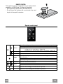
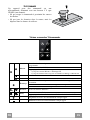
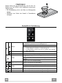
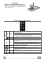
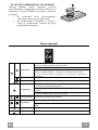
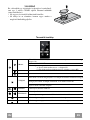
REMOTE CONTROL
This appliance can be commanded using a remote control,
powered by a CR2032 type 3 V battery (not supplied).
• Do not place the remote control near heat sources.
• Do not discard the batteries with normal waste, they must
be put into the specific containers.
Remote control panel
Motor
Door Closed: Opens the door and turns the motor on at the last speed set.
Door Open: Motor On / Off
Pressed for 2 Seconds:
a) If the door is open, Motor + Lights Off.
b) If the door is closed, Opens the door and Lights + M
o
tor On.
- -
- -
Light
Door Closed: Opens the door half way and turns the Lights on a Maxi-
mum Intensity.
Door open half way: Turns lights off and closes the door.
Door Open: Lights On / Off.
Intensive
Activates the Intensive function.
Delay
Activates the Delay function.
Pressed for 2 Seconds:
Activates / Deactivates the 24H function.
-
Increases the working speed each time it is pressed.
-
Decreases the working speed each time it is pressed.

EN
1
4
14
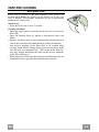
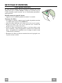
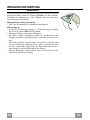
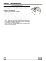
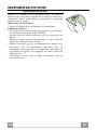
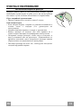
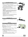
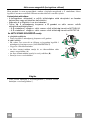
CARE AND CLEANING
Metal grease filters
Filters can be washed in the dish machine. They need to be
washed when Drop-sign appears on the display or in any case
every 2 months, or even more frequently in case of particularly
intensive use of the hood.
Alarm reset
• Press the G–key for at least 2 seconds.
Cleaning the filters
• Open the upper panel by pressing the A-key for 1 second (see
Part USE).
• Open the Bottom Door by pulling it downwards with your
hands.
• Remove the filters one by one pushing them towards the back
side of the hood unit and simultaneously pulling downwards.
• Any kind of bending of the filters has to be avoided when
washing them. Before fitting them again into the hood make
sure that they are completely dry. (The colour of the filter sur-
face may change throughout the time but this has no influence
to the filter efficiency).
• When fitting the filters into the hood pay attention that they are
mounted in correct position the handle facing outwards.

EN
1
5
15
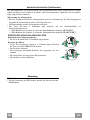
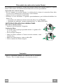
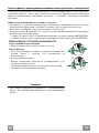
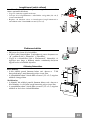
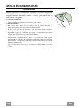
Activated Charcoal Filter (Recirculation Version)
This cannot be washed or regenerated, and must be changed when the C symbol on the display
appears, or at least once every 4 months. The Alarm signal must be activated in advance.
Activating the alarm signal
• In Recirculation Version Hoods, the Filter Saturation Alarm must be activated on
installation or at a later date.
• Turn the Lights and the Suction Motor off.
• Press and hold button D for approximately 5 seconds to enable / disable the A.C. Filters
• Symbol C flashes twice, A.C. Filter saturation alarm ACTIVATED
• Symbol C flashes once, A.C. Filter Saturation alarm DEACTIVATED
REPLACING THE CHARCOAL FILTER
Alarm reset
• Press the G-key for at least 2 seconds.
Replacing the filter
• Open the upper panel by pressing the A-key for about a second
(see Part USE).
• Remove the metal filters.
• Remove the saturated charcoal filter as indicated (A).
• Fit the new filters as indicated (B).
• Put the metal grease filters in their seats.
A
B
Lighting unit
• For replacement contact technical support ("To purchase
contact technical support").

FR
1
6
16
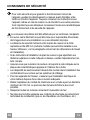
CONSIGNES DE SÉCURITÉ
Pour votre sécurité et pour garantir le fonctionnement correct de
l’appareil, veuillez lire attentivement ce manuel avant d’installer et de
mettre en fonction l’appareil. Toujours conserver ces instructions avec
l’appareil, même en cas de cession ou de transfert à une autre personne.
Il est important que les utilisateurs connaissent toutes les caractéristiques
de fonctionnement et de sécurité de l’appareil.
La connexion des câbles doit être effectuée par un technicien compétent.
• En aucun cas le fabricant ne peut être tenu pour responsable d’éventuels
dommages dus à une installation ou à une utilisation impropre.
• La distance de sécurité minimum entre le plan de cuiss
on et la hotte
aspirante est de 650 mm (certains modèles peuvent être installés à une
hauteur inférieure ; voir le paragraphe concernant les dimensions de travail
et l’installation).
• Si les instructions d’installation du plan de cuisson à gaz spécifient une
distance supérieure à celle indiquée ci-dessus, veuillez impérativement en
tenir compte.
• Assurez-vous que la tension du secteur correspond à celle indiquée sur la
plaque des caractéristiques apposée à l’intérieur de la hotte.
• Les dispositifs de sectionnement doivent être montés dans l’installation fixe
conformément aux normes sur les systèmes de câblage.
• Pour les appareils de Classe I, s’assurer que l’installation électrique de
votre intérieur dispose d’une mise à la terre adéquate.
• Reliez l’aspirateur du conduit de cheminée avec un tube ayant un diamètre
minimum de 120 mm. Le parcours des fumées doit être le plus court
possible.
• Respecter toutes les normes concernant l’évacuation de l’air.
• Ne reliez pas la hotte aspirante aux conduits de chemi
née qui acheminent
les fumées de combustion (par ex. de chaudières, de cheminées, etc.).

FR
1
7
17
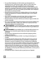
•
Si vous utilisez l’aspirateur en même temps que des appareils non
électriques (par ex. fonctionnant au gaz), veillez à ce que la pièce soit
adéquatement ventilée, afin d’empêcher le retour du flux des gaz
d’évacuation. Si vous utilisez la hotte de cuisine en même temps que des
appareils non alimentés à l’électricité, la pression négative dans la pièce ne
doit pas dépasser 0,04 mbar, afin d’éviter que les fumées soient réaspirées
dans la pièce où se trouve la hotte.
• Ne pas évacuer l’air à travers une conduite utilisée pour l’évacuation des
fumées des appareils de combustion alimentés au gaz ou avec d’autres
combustibles.
• Si le cordon d’alimentation est endommagé, faites-le remplacer par le
fabricant ou par un technicien d’un service après-vente agréé.
• Branchez la fiche à une prise conforme aux normes en vigueur et dans une
position accessible.
• En ce qui concerne les dimensions techniques et de sé
curité à adopter pour
l’évacuation des fumées, veuillez vous conformer scrupuleusement aux
règlements établis par les autorités locales.
AVERTISSEMENT : Avant d’installer la hotte, retirer les films de protection.
• Utilisez exclusivement des vis et des petites fournitures du type adapté pour
la hotte.
AVERTISSEMENT toute installation de vis et de dispositifs de fixation non
conformes à ces instructions peut entraîner des risques de décharges
électriques.
• Ne pas observer directement avec des instruments optiques (jumelles,
lentilles grossissantes...).
• Ne flambez pas des mets sous la hotte : sous risque de développer un
incendie.
• Cet appareil peut être utilisé par des enfants de plus de 8 ans et par des
personnes dont les capacités physiques, sensorielles ou mentales sont
diminuées ou ayant une expérience et des connaissances insuffisantes,
pourvu que ce soit sous la surveillance attentive d’une personne responsable
et après avoir reçu des instructions sur la manière d’utiliser cet appareil en
toute sécurité et sur les dangers que cela comporte. Assurez-vous que les
enfants ne jouent pas avec cet appareil. Le nettoyage et l’entretien de la part
de l’utilisateur ne doivent pas être effectués par des enfants, à moins qu’ils ne
soient surveillés.
• Surveillez les enfants. S’assurer qu’ils ne jouent pa
s avec l’appareil.

FR
1
8
18
•
Cet appareil n’est pas destiné à être utilisé par des personnes (enfants
compris) dont les capacités physiques, sensorielles ou mentales sont
diminuées ou ayant une expérience et des connaissances insuffisantes, à
moins que celles-ci ne soient attentivement surveillées et instruites.
Les parties accessibles peuvent devenir très chaudes durant l’utilisation
des appareils de cuisson.
• Nettoyer et/ou remplacer les filtres après le délai indiqué (danger
d’incendie). Voir le paragraphe Nettoyage et Entretien.
• Veillez à ce que la pièce bénéficie d’une ventilation adéquate lorsque la
hotte fonctionne en même temps que des appareils utilisant du gaz ou
d’autres combustibles (non applicable aux appareils qui évacuent l’air
uniquement dans la pièce).
• Le symbole
marqué sur le produit ou sur son emballage indique que ce
produit ne peut pas être éliminé comme déchet ménager normal. Lorsque
ce produit doit être éliminé, veuillez le remettre à un centre de collecte
prévu pour le recyclage du matériel électrique et électronique. En vous
assurant que cet appareil est éliminé correctement, vous participez à
prévenir des conséquences potentiellement négatives pour l'environnement
et pour la santé, qui risqueraient de se présenter en cas d’élimination
inappropriée. Pour toute information supplémentaire sur le recyclage de ce
produit, contactez votre municipalité, votre déchetterie locale ou le magasin
où vous avez acheté ce produit.

FR
1
9
19
CARACTERISTIQUES
Composants
Réf. Q.té Composants du produit
1 1 Corps de Hotte comprenant : Commandes, Éclairage,
Groupe Ventilation, Filtres
2.1 1 Conduit supérieur
2.2 1 Conduit inférieur
8 1 Grille orientable Sortie de l’Air
9 1 Buse de réduction 150--120
10 1 Buse avec clapet (Si fourni)
16 1 Couverture filtrante
Réf. Q.té Composants de l’installation
7.2.1 2 Équerre de fixation du conduit supérieur
11 5 Chevilles
11a 2 Chevilles SB 12/10
12a 5 Vis 4,2 x 44,4
12c 10 Vis 2,9 x 6,5
12e 2 Vis 2,9 x 9,5
Q.té Documentation
1 Notice d’emploi
2.1
2.2
12c
12a
7.2.1 11
11
12a
10
9
1
16
12c
12d
8
11a

FR
2
0
20
Encombrement
Les dimensions varient selon la version que vous allez choisir
50
649
MIN 530 MAX 990
463
339
800
749
500
91
898
570
300
200
50
649
MIN 330 MAX 590
463
339
800
749
300
91
898
570
300
200
La page est en cours de chargement...
La page est en cours de chargement...
La page est en cours de chargement...
La page est en cours de chargement...
La page est en cours de chargement...
La page est en cours de chargement...
La page est en cours de chargement...
La page est en cours de chargement...
La page est en cours de chargement...
La page est en cours de chargement...
La page est en cours de chargement...
La page est en cours de chargement...
La page est en cours de chargement...
La page est en cours de chargement...
La page est en cours de chargement...
La page est en cours de chargement...
La page est en cours de chargement...
La page est en cours de chargement...
La page est en cours de chargement...
La page est en cours de chargement...
La page est en cours de chargement...
La page est en cours de chargement...
La page est en cours de chargement...
La page est en cours de chargement...
La page est en cours de chargement...
La page est en cours de chargement...
La page est en cours de chargement...
La page est en cours de chargement...
La page est en cours de chargement...
La page est en cours de chargement...
La page est en cours de chargement...
La page est en cours de chargement...
La page est en cours de chargement...
La page est en cours de chargement...
La page est en cours de chargement...
La page est en cours de chargement...
La page est en cours de chargement...
La page est en cours de chargement...
La page est en cours de chargement...
La page est en cours de chargement...
La page est en cours de chargement...
La page est en cours de chargement...
La page est en cours de chargement...
La page est en cours de chargement...
La page est en cours de chargement...
La page est en cours de chargement...
La page est en cours de chargement...
La page est en cours de chargement...
La page est en cours de chargement...
La page est en cours de chargement...
La page est en cours de chargement...
La page est en cours de chargement...
La page est en cours de chargement...
La page est en cours de chargement...
La page est en cours de chargement...
La page est en cours de chargement...
La page est en cours de chargement...
La page est en cours de chargement...
La page est en cours de chargement...
La page est en cours de chargement...
La page est en cours de chargement...
La page est en cours de chargement...
La page est en cours de chargement...
La page est en cours de chargement...
La page est en cours de chargement...
La page est en cours de chargement...
La page est en cours de chargement...
La page est en cours de chargement...
La page est en cours de chargement...
La page est en cours de chargement...
La page est en cours de chargement...
La page est en cours de chargement...
La page est en cours de chargement...
La page est en cours de chargement...
La page est en cours de chargement...
La page est en cours de chargement...
La page est en cours de chargement...
La page est en cours de chargement...
La page est en cours de chargement...
La page est en cours de chargement...
-
 1
1
-
 2
2
-
 3
3
-
 4
4
-
 5
5
-
 6
6
-
 7
7
-
 8
8
-
 9
9
-
 10
10
-
 11
11
-
 12
12
-
 13
13
-
 14
14
-
 15
15
-
 16
16
-
 17
17
-
 18
18
-
 19
19
-
 20
20
-
 21
21
-
 22
22
-
 23
23
-
 24
24
-
 25
25
-
 26
26
-
 27
27
-
 28
28
-
 29
29
-
 30
30
-
 31
31
-
 32
32
-
 33
33
-
 34
34
-
 35
35
-
 36
36
-
 37
37
-
 38
38
-
 39
39
-
 40
40
-
 41
41
-
 42
42
-
 43
43
-
 44
44
-
 45
45
-
 46
46
-
 47
47
-
 48
48
-
 49
49
-
 50
50
-
 51
51
-
 52
52
-
 53
53
-
 54
54
-
 55
55
-
 56
56
-
 57
57
-
 58
58
-
 59
59
-
 60
60
-
 61
61
-
 62
62
-
 63
63
-
 64
64
-
 65
65
-
 66
66
-
 67
67
-
 68
68
-
 69
69
-
 70
70
-
 71
71
-
 72
72
-
 73
73
-
 74
74
-
 75
75
-
 76
76
-
 77
77
-
 78
78
-
 79
79
-
 80
80
-
 81
81
-
 82
82
-
 83
83
-
 84
84
-
 85
85
-
 86
86
-
 87
87
-
 88
88
-
 89
89
-
 90
90
-
 91
91
-
 92
92
-
 93
93
-
 94
94
-
 95
95
-
 96
96
-
 97
97
-
 98
98
-
 99
99
-
 100
100


Faber MIRROR BK BRS X/V A90 LOGIC Le manuel du propriétaire
- Catégorie
- Hottes
- Taper
- Le manuel du propriétaire
Autres documents
-
AEG DD9996-B Manuel utilisateur
-
-
-
-
ROBLIN Creatix 800 Le manuel du propriétaire
-
Aeg-Electrolux dd 9996 Le manuel du propriétaire
-
ROBLIN CREATIX BK Le manuel du propriétaire
-
-
-
Smeg KMN75AB Fiche technique