
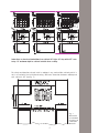
INSTRUCTION MANUAL
MANUEL D’INSTRUCTIONS
Cooktops - Table de cuisson
code:
7216 942
7217 942
7055 962
7245 962
7637 900
7647 900
7638 900
7648 900
7639 900
7649 900
7640 900
7650 900
EN p. 3
FR p. 21


COOKTOPS MODELS
index:
Installation instructions pag. 6
Maintenance pag. 18
Warranty pag. 19
EN

-4-
IMPORTANT SAFETY INSTRUCTIONS
Important: keep these instructions for future need.
Read and follow all instructions before using this appliance to prevent the potential risk of
re, electrical shock, personal injury or damage to the appliance as a result of improper
usage of the appliance.
IMPORTANT SAFEGUARDS
Proper installation. Be sure your appliance is properly installed and grounded by a qualied
technician.
Never use your appliance for warming or space heating. This information is based on safety
considerations.
Do not leave children and pets alone. Children and pets should not be left alone or unattended
in area where appliance is in use. They should never be allowed to sit or stand on any part of
the appliance.
Wear proper apparel. Loose tting or hanging garments should never be worn while using the
appliance. In the event that personal clothing catches on re, DROP AND ROLL IMMEDIA-
TELY to extinguish ames.
User servicing. Do not repair or replace any part of the appliance unless specically recom-
mended in the manual. All other servicing should be referred to a qualied technician.
Storage in or on appliance.
Flammable materials should not be stored on or near surface units.
Do not use water on grease res. SMOTHER FLAMES with a close-tting lid or other metal tray,
then turn off the gas burner. BE CAREFUL in order to prevent burns. If the ames do not go
out immediately, EVACUATE AND CALL THE FIRE DEPARTMENT. NEVER use water or a wet
dishcloth or towel on grease res: a violent steam explosion may result. Use dry chemical or
foam-type extinguisher.
Use a re extinguisher only if:
• you have a class ABC extinguisher, and know how to operate it;
• the re is small, and conned to the area where it origi
nally started;
• you can ght it with your back to the exit
• the Fire Department has already been called
Use only dry potholders. Moist or damp potholders on hot surfaces may result in burns from
steam. Do not let potholder touch heating elements. Do not use a towel or other bulky cloth.
Use proper pan size. This appliance is equipped with one or more gas burners of different
size. Select pans having at bottoms large enough to cover the burner ame area. The ame
should NOT extend beyond the bottom of the pan. Beware that direct contact with the ame
may result in ignition of clothing. Proper relationship of pan to burner size will also improve
efciency.

-5-
Never leave surface units unattended at high heat settings. Boilovers causes smoking and greasy
spillovers that may ignite.
Protective liners. Do not use aluminium foil to line surface unit drip bowls, except as sugge-
sted in the manual. Improper installation of these liners may result in a risk of electric shock,
or re.
Glazed cooking utensils. Only certain types of glass, glass/ceramic, ceramic, earthenware, or
other glaze utensils are suitable for cooktop service without breaking due to the sudden chan-
ge in temperature.
Utensils handles should be turned inward and not extended over adjacent surface units. To reduce
the risk of burns, ignition of ammable materials, and spillage due to unintentional contact
with the utensil, the handle of a utensil should be positioned so that it is turned inward, and
does not extend over adjacent surface units.
Do not touch surface units or areas near units. Surface units may be hot even though they are
dark in colour. Areas near surface units may become hot enough to cause burns. During and
after use, do not touch, or let clothing or other ammable materials contact surface units or
areas near units until they have had sufcient time to cool. Other surfaces of the appliance
may become hot enough to cause burns. Among these areas and surfaces are the cooktop and
surfaces facing the cooktop.
Do not heat unopened food containers. Build-up of pressure may cause container to burst result
in injury.
Clean ventilating hoods frequently. Grease should not be allowed to accumulate on hood or lter
(when a cooking hood is installed with appliance).
In case of re, if the hood is functioning TURN IT OFF. The fan, if operating, may spread the
ame.
CALIFORNIA PROPOSITION 65 - Warning: burning gas cooking fuel generates by-products which
are on the list of substances known by the State of California to cause cancer or reproductive
harm. In order to minimize exposure to these substances, be careful to always operate this
appliance in accordance with the instructions contained in this manual and provide proper
ventilation.
WARNING: This appliance should not be installed with a ventilation system that blows air
downward toward the appliance. This type of ventilation system may cause ignition and com-
bustion problems with the gas cooking appliance resulting in personal injury or unintended
operation.
WARNING Air curtain hoods or other overhead range hoods, which operate by blowing a
downward airow downward towards the appliance, shall not be used in conjunction with this
gas appliance unless the hood and range have been designed and tested in accordance with
the Standard for Domestic Gas Ranges ANSI Z21.1 – CSA1.1 and listed by an independent
testing laboratory for combination use.
CAUTION: Do not store items of interest to children in cabinets above cooktop or on
the backguard of a cooktop, children climbing on the cooktop to reach items could be
seriously injured.
!

-6-
INSTALLATION INSTRUCTIONS
SPECIAL WARNING:
Only qualied personnel should install or service this cooktop. Read “safety instructions”
in this book before using cooktop. Improper installation, adjustement, alteration, service,
maintenance or use of the appliance can result in serious injury or property damage.
Installation must conform with local codes or, in the absence of codes, the National Fuel
Gas Code, ANSI Z223.1 / NFPA 54 or latest edition. In Canada, installation must be in
accordance with the current CAN/CGA B149.1 & 2 Gas Installation Codes and/or local
codes.Electrical installation must be in accordance with local codes or, in the absence
of local codes, with the National Electric Code ANSI/NFPA n. 70 - latest edition. In
Canada, the current CSAC22.1 Canadian Electrical Code part 1 and/or local codes.
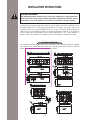
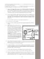
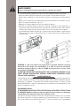
CLEARANCE DIMENSIONS
For complete information regarding the installation of wall cabinets above the cooktop
and clearances to combustible wall above the cooking top see the installation drawing
(allow 5” clearance under cooktop for gas connection):
!

-7-
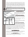
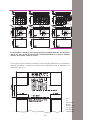
Instructions are based on Standard American cabinets 36” high x 24” deep with a 25” coun-
tertop. 13” maximum depth for cabinets installed above cooktop.
For safety considerations do not install a cooktop in any combustible cabinetry which is
not in accord with the installation drawing. Minimum dimension between cooktop and
wall cabinet is 30” (see g. 1).
Fig. 1
Dimensions
are minimum
clearances to
combustible
materials
Above counter 30” min.
to combustible surface
Depth from back wall
cabinet 13” max
hood depth 24” max

-8-
The 30 inch (76 cm) dimension may be reduced to not less than 24 in (61 cm) when
the wall cabinets in a domestic home are protected with reproof materials in accordan-
ce with American National Standards - National Fuel Gas Code. To eliminate the risk of
burns or re by reaching over heated surface units, cabinet storage space located above
the surface units should be avoided. If cabinet storage is to be provided, the risk can
be reduced by installing a range hood that projects horizontally a minimum of 5 in (13
cm) beyond the edge of the cabinets. Minimum distance between the cooktop and the
rear wall is 1” ¾. Minimum distance between the front edge of the counter and the
cooktop’s front edge is 2”.
CAUTION:
Some cabinets and building materials are not designed to withstand the heat
produced by the normal safe operation of a listed appliance. Discoloration or damage, such
as delamination, may occur.
LOCATING THE COOKTOP
Do not set cooktop on locations where it may be
subject to strong drafts. Any opening in the wall
behind the cooktop should be sealed. Make
sure the ow of combustion or ventilation air is
not obstructed.
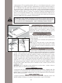
FIXING THE COOKTOP TO COUNTERTOP
A kit of sealing gasket is supplied within the
cooktop package. Install the sealing gasket
around the top surface of the cut-out perime-
ter.
This sealing gasket prevents liquids from
leaking under the cooktop.
NOTE: Do not use caulk or silicon to x cooktop
to countertop. The cooktop must be readily re-
movable for service.
COOKTOP CLAMP DOWN INFORMATION
Before unit is installed in counter opening, you
must apply supplied xing brackets to cooktop.
Insert bracket with offset side of angle into un-
derneath cover slot on front and back side of unit. Put in place xing screw, without
tightening, so the bracket can slide in and out. Keeping brackets slid-in, install cooktop
in counter opening. Once units is installed, clamp down cooktop by sliding out xing
brackets and placing its external tip on counter underneath surface, then tighten screws
slightly (over tightening may cause damage to cooktop) till unit is rmly blocked.
Once cooktop is xed in place, remove sealing gasket excess by using a cutter or a sharp
edge tool. IMPORTANT for solid surface material installation: please insert a wooden
block between the clamp and the bottom of the countertop.
VENTILATION
Ventilation must be in accordance with local installation code. The appliance must
be installed in a well-ventilated environment to guarantee a correct combustion gas
exchange, proper air circulation and working temperature within safety limits.
MODEL NUMBER PLATE
The model number plate is located on the bottom case of the cooktop. A second model
number plate is applied on the front page of the instruction booklet.
!

-9-
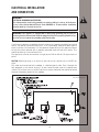
ELECTRICAL INSTALLATION
AND CONNECTION
WARNING.
ELECTRICAL GROUNDING INSTRUCTIONS
The cooktop must be electrically grounded in accordance with local codes or, in the absence
of local codes, with the National Electric Code ANSI/NFPA n. 70 latest edition. Installation
should be made by a licensed electrician.
WARNING
: This appliance is equipped with a (three-prong) grounding plug for your pro-
tection against shock hazard and should be plugged directly into a properly grounded recep-
tacle. Do not cut or remove the grounding prong from the plug.
!
If you have any doubt as to whether the wall receptacle is properly grounded, you should
have it checked by a qualied electrician. If an ungrounded, two-hole or other type of
electrical outlet is encountered, it is the personal responsibility of the appliance owner
to have the outlet replaced with a properly grounded three-hole electrical outlet. This
should be done by a licensed electrician.
The appliance must be connected to a single-phase 120 Vac 60 Hz 15 amps electrical
outlet.
CAUTION: Before you plug in an electrical cord, be sure all controls are in the OFF po-
sition.
The cable cord connected to the cooktop, is a exible type of cable. Pass it through the
hole prepared in the cabinet to plug it to wall socket located under the cooktop area
cabinet. To facilitate service, the ex cable must not be shortened and should be routed
to permit temporary removal of the cooktop.
!
Electrical diagrams

-10-
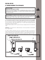
WARNING
Disconnect electrical supply before servicing the appliance.
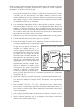
When the exible cord has to be changed it is necessary to follow the procedure descri-
bed hereafter:
- Turn off main gas shut-off valve and disconnect electrical supply
- Pull out entire cooktop from the counter by loosing the xing brackets
- Disconnect gas supply connector from cooktop manifold
- Open un connecting terminal block cover, see g. 2
- Open exible cord lock and loosen the old cord prongs from terminal block
- Connect new exible cord prongs to terminal block and x exible cord lock, remem-
bering that the earth wire (green) must be longer by one inch than the other ones. For
Line and Neutral wire connection, follow signs on terminal block
- The exible cord must be hold tight by the cord lock, in such a way that it may not
be pulled out. The exible cord path must not be in proximity or in contact with hot
surfaces that may damage the cord itself.
Fig. 2
ATTENTION: The exible cord must be in accordance with National Electrical Codes and
suitable for the hob technical characteristics electrical ratings. A 18 AWG three-prong groun-
ding plug exible cord, type SJT3x18AWG.
THE MANUFACTURER DECLINES ANY RESPONSIBILITY FOR IMPROPER INSTALLATION, ADJU-
STEMENT, ALTERATION, SERVICE, MAINTENANCE OR USE OF THE APPLIANCE, WHICH MAY
RESULT IN SERIOUS INJURY OR PROPERTY DAMAGE.
GAS SUPPLY
Installation of this cooktop must conform with local codes or, in the absence of local
codes, with the National Fuel Gas Code, ANSI Z223.1/NFPA 54 latest edition.
In Canada the cooktop must be installed in accordance with the current CGA Standard
CAN/CGA-B149 - Installation Codes for Gas Burning Appliances and Equipment and/or
local codes.
GAS SUPPLY CONNECTION:
A TRAINED SERVICEMAN OR GAS APPLIANCE INSTALLER MUST MAKE THE GAS SUPPLY CON-
NECTION.
Leak testing of the appliance shall be conducted by the installer according to the instructions
given in this section.
This appliance should be installed and used with the supplied pressure regulator. Inlet
!
Fig. 2

-11-
pressure to the regulator should not exceed 4 in. w.c. for use with natural gas, and 11
in. w.c. for use with LP gas.
Inlet pressure in excess of 14 in. w.c. can damage the appliance pressure regulator, or
other gas component in this appliance and can result in a gas leak.
a) A gas cut-off valve should be put in an accessible location in the supply line
ahead of the cooktop, for turning on and turning off gas supply. If cooktop is to
be connected to house piping with exible or semi-rigid metal connectors for gas
appliances, connectors nuts must not be connected directly to pipe threads. The
connectors must be installed with adapters provided with the connector.
b) The house piping and/or cooktop connector used to connect the cooktop to the
main gas supply must be clean, a free of metal shavings, rust, dirt and liquids
(oil or water). Dirt in the supply lines can work its way into the cooktop manifold
and in turn cause failure of the gas valves or controls and clog burners and/or
pilot orices.
c) Turn off all pilots and main gas valve of other gas appliances.
d) Turn off main gas valve at meter.
e) Before connecting cooktop apply pipe thread compound approved for LPG to all
threads.
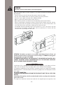
f) After installing a gas shut-off valve in an
easily accessible location under the unit
(see g. 3), install the pressure regulator
(supplied) to manifold pipe using Teon®
tape on threads of manifold pipe. To pre-
vent possible damage to the gas pressure
regulator, install it after the rough-in box
is in its permanent position.
CAUTION: do not attempt any adjustment
of the pressure regulator, except conver-
sion to propane. Connect the gas supply
line to the unit pressure regulator using a
1/2” ex gas line connector between wall
shut-off valve and pressure regulator (see
complete procedure in g. 3).
g) After installing the pressure regulator, the installer must check the manifold
pressure; this can be done by connecting a proper metering device to the 1/8
NPT thread directly on the pressure regulator.
h) For model 7216 942 - 7217 942: this cooktop has two manifold gas inlet (one
on the far right and one on the far left of the cooktop): two separate pressure re-
gulators are supplied, and must be installed, one on each side, as per procedure
described in point f) of this paragraph.
i) See rating plate for type of gas the cooktop has been manufactured for.
j) Turn on main gas valve at meter, and relight pilots at other gas appliances.
k) Apply a non-corrosive leak detection uid to all joints and ttings in the gas
connection between the supply line shut-off valve and the cooktop. This inclu-
des gas ttings and joints in the cooktop if connections were disturbed during
Fig. 3
Fig. 3

-12-
installation. Check for leaks! Bubbles appearing around ttings and connections
will indicate a leak. If a leak appears, turn off supply line gas shut off valve, and
retest for leaks.
CAUTION: NEVER CHECK FOR LEAKS WITH A FLAME. WHEN LEAK CHECK IS
COMPLETE, WIPE OFF ALL RESIDUE
l) Remove shipping polystyrene from ALL cooktop burners. The polystyrene is
meant to hold the burners in place on the burners’ base, and should be used for
shipping purposes only.
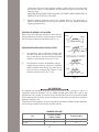
CHECKING THE BURNERS’ INSTALLATION
Make sure that the burners and burner covers are pro-
perly positioned, that they t into each-other securely,
and that they are perfectly horizontal (see g. 4).
CHECKING PRESSURE OF HOUSE PIPING SYSTEM
1) The appliance and its individual shutoff valve
must be disconnected from the gas supply pi-
ping system during any pressure testing of that
system at test pressure in excess of ½ psi.
2) The appliance must be isolated from the gas
supply piping system by closing its individual
manual shutoff valve during any pressure te-
sting of the gas supply piping system at test
pressure equal to or less than ½ psi.
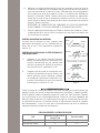
GAS CONVERSION
All cooktops are equipped with both Natural Gas and LP gas injectors as well as a
convertible pressure regulator. The unit model number plate states which gas it was
adjusted for at the factory. To convert the unit to either Natural gas or LP gas one should
t the proper burner injectors, adjust the burners for low ame and adjust the pressure
regulator converter cap.
Inlet pressure to the appliance pressure regulator should be as follows for both operation
and checking of appliance pressure regulator setting:
MANIFOLD PRESSURE
Fig. 4
Gas
Pressure in inches
of water column
Pressure in kPa
Natural gas 4 1
LP gas 11 2.7

-13-
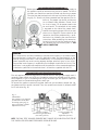
GAS BURNER INJECTOR CONVERSION
Before proceeding with the conversion, shut off the gas supply to
the appliance prior to disconnecting electrical power. To switch
injectors, one should unscrew the installed injector using a proper
7mm hex. key tool and replace it with new injector for new gas set-
ting (g. 5). Save the injectors removed from the appliance for fu-
ture use. The proper injector for each burner
has a different hole diameter. Please check
the chart at page 15 for proper nozzle size
for each burner. The diameter of the nozzle
is engraved on the side of the nozzle itself.
Should the engraving prove difcult to read,
please use a magnier. Please note that the
conversion should be performed by a quali-
ed technician, following the manufacturer’s
instructions. After performing the conversion,
the technician must test the appliance for le-
aks, following the instructions given in “GAS
SUPPLY CONNECTION”.
Fig. 5
WARNING
This conversion kit shall be installed by a qualied service agency in accordance with
the manufacturer’s instructions and all applicable codes and requirements of the
authority having jurisdictions is not followed exactly, a re, explosion or production of
carbon monoxide may result causing property damage, personal injury or loss of life.
The qualied service agency is responsible for the proper installation of this kit. The
installation is not proper and complete until the operation of the converted appliance
is checked as specied in the manufacturer’s instructions supplied with the kit.
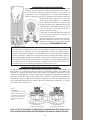
APPLIANCE PRESSURE REGULATOR CONVERSION
The unit appliance pressure regulator must be set to match the type gas supply used. If
converting from natural gas to LP gas, the appliance pressure regulator must be conver-
ted to regulate LP gas. If converting from LP gas to natural gas, the appliance pressure
regulator must be converted to regulate natural gas.
To convert the appliance pressure regulator from one gas to another: remove the cap,
push down and turn counter-clockwise. Turn the cap over and reinstall it, follow the NAT
or LP indication (g. 6).
NOTE: THE GAS TYPE YOU ARE CONVERTING TO MUST BE VISIBLE ON THE TOP OF
THE INSTALLED APPLIANCE PRESSURE REGULATOR CAP.
Pressure regulator
natural/town gas adjustment
(low outlet pressure)
Fig. 6
ATTENTION
The regulator is pre adjusted
for both values. Aside from
the turning of the plug (1),
there is no further customer
adjustment necessary.
Pressure regulator lpg
adjustment
(high outlet pressure)
Fig. 5-A
Fig. 5-B

-14-
SERVICE - PARTS INFORMATION
When your cooktop requires service or replacement parts, contact your dealer or autho-
rized service agency. Please give the complete model and serial number of the cooktop
which is located on the cooktop model number plate.
Should you fail to locate the required replacement parts locally, please contact the
Nationwide service organization (for Canada and the U.S.A.):
Foster Service Center
7575 E Redield Rd #129, Scottsdale, AZ 85260
Telephone (888) 639-6001
E-mail: [email protected]
Fax: (480)998-7877
For Massachusetts installations:
1. Shut-off valve must be a “T” handle gas cock
2. Flexible gas connector must not be longer than 36 inches
3. Not approved for installation in a bedroom or a bathroom unless unit is direct
vent
CHECK OF GAS PRESSURE AFTER THE INSTALLATION OF THE PRESSURE REGULATOR
The gas pressure in the cooktop’s manifold should be checked by a qualied installer,
after the pressure regulator has been installed and tested. To do this, a 1/8 NPT thread
is provided directly onto the pressure regulator. Connect a proper metering device to the
thread in order to measure the pressure. In order to check the pressure regulator, the
inlet pressure should be at least 1 in. water column more than the regulated manifold
pressure.

-15-
Fig. 7
LOW SETTING VALVE ADJUSTEMENT
The low setting should produce a stable ame when tur-
ning the knob from max to min. The ame should be
1/8 inch (3,2 mm) or lower and must be stable on all
ports on low setting. To adjust: operate burner on max for
about ve minutes to properly heat the burner itself. Turn
knob back to min; remove knob, and insert a small at
tip screwdriver into the centre of the valve stem. Adjust
the ame size by turning adjustment screw in either di-
rection, while holding the stem to prevent it from rotating
(g. 7).
Flame must be of sufcient size to be stable on all burner ports. If ame adjustment is
needed, adjust only on the low setting. Never adjust ame size on higher setting.
When a two-way gas tap is present there are two screws for minimum gas ow adjustment.
NOTE: all gas adjustment should be done by qualied service personnel only
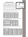
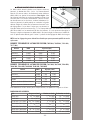
COOKTOP TECHNICAL DATA (7055 962, 7245 962, 7216 942, 7217 942)
Burner BTU/hr Injector (mm)
Natural Propane
Auxiliary 2.800 0,80 0,50
Semi-rapid 5.100 1,10 0,65
Rapid 7.600 1,30 0,82
Triple crown 11.000 1,60 0,95
COOKTOP TECHNICAL DATA (7637 900, 7647 900, 7638 900, 7648 900, 7639 900,
7649 900, 7640 900, 7650 900)
Burner BTU/hr Injector (mm)
Natural Propane
Auxiliary 5.000 1,05 0,63
Semi-rapid 9.100 1,45 0,86
Rapid 10.750 1,55 0,92
Double crown (inside burner)
15.500
0,90 0,53
Double crown (external crown) 1,70 1,00
To identify the right nozzle for each burner, please refer to the gure embedded on the
nozzle itself.
DIMENSIONS OF THE APPLIANCES
Mod. Width in (mm) Height in (mm) Depth in (mm)
7055 962 33
55
/
64
(860) 1
49
/
64
(45) 19
11
/
16
(500)
7245 962 34
3
/
8
(873) 2
3
/
32
(53) 20
13
/
64
(513)
7216 942-7217 942 54
31
/
64
(1384) 2
9
/
16
(65) 13
31
/
32
(355)
7637 900-7647 900 32
9
/
32
(820) 2
53
/
64
(72) 22
3
/
64
(560)
7638 900-7648 900 41
37
/
64
(1056) 2
53
/
64
(72) 22
3
/
64
(560)
7639 900-7649 900 45
7
/
16
(1154) 2
53
/
64
(72) 22
3
/
64
(560)
7640 900-7650 900 42
33
/
64
(1080) 2
53
/
64
(72) 19
19
/
64
(490)
Fig. 7

-16-
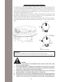
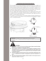
INSTRUCTION GUIDE FOR GAS COOKTOP
For models with single action automatic ignition, place a pan on the burner grate. Push
in and turn the knob counterclockwise to the max setting. A clicking sound will be he-
ard and the burner will ignite, g. 8. The ignitors of all the burners will spark when any
control knob is operated. Keep the knob pushed in until the burner ignites, then turn
the knob to the desired ame size, g. 9.
For models equipped with both electronic ignition and safety device, follow the same
procedure, but keep pushing in for at least 4 seconds until the thermocouple is hot
enough. Then release the knob; the burner should remain on.
If the burner does not light within 4 seconds, turn the burner off. Check to see that the
cap is positioned correctly on the burner base and the igniter is clean and dry, then try
again.
!
CAUTION:
1) Do not store or use gasoline or other ammable vapours, liquids or items in the vicinity
of this or any other appliance.
2) Do not obstruct the ow of combustion and ventilation air by blocking the room vents
or air intakes. Restriction of air ow to the gas appliance prevents proper performance
and increases carbon monoxide emission to unsafe levels.
3) Continuously use of the appliance may need extra ventilation, this can be solved by just
opening a window or increasing exhaust power of a cooking hood.
4) To prevent are ups do not use the cooktop without all burner caps properly positioned.
5) To prevent are ups all grates must be properly positioned on the cooktop whenever the
cooktop is in use. Each of the four feet must be placed into the corresponding dimples
!
Fig. 8
Fig. 8
17
OFF indicator
HIGT
(MAX)
LOW (MIN)
MAX 1
MAX 2
MAX 1
MIN 2
MAX 1
OFF 2
MIN 1
OFF 2
1 INSIDE BURNER
2 EXTERNAL CROWNS
OFF indicator
Fig. 9
Burner control knobs
WARNING
NEVER use this appliance as a space heater to heat or warm the room.
Doing so may result in carbon monoxide poisoning and overheating of the cooktop.

-17-
!
in the cooktop’s steel surface. Do not use a grate if the rubber feet are missing or da-
maged.
6) Without power supply, the cooktop won’t ignite. In this case, to ignite the cooktop, use
a match or a lighter, taking care to put the knob on the minimum gas ow position.
However, should the power supply fail during cooking, the cooktop will continue to
work properly. This means that the ame won’t go out, and that the safety thermocouple
will also continue to work properly, as they do not need electrical power to function.
However, please beware that the cooker hood may not work without power, and thus fail
to aspire the fumes.
COOKWARE
To achieve optimum surface cooking performance, select heavy gauge, at, smooth
bottom pans that conform to the diameter of the cooking area as well as straight sides.
Remember to use pans with at bottoms and handles that are easily grasped and stay
cool. To minimize burns, ignition of ammable materials and spillage due to uninten-
tional contact with the utensil, do not extend handles over adjacent surfaces burners.
Always turn pan handles toward the side or back of the appliance, not out into the room
where they may be easily hit or reached by small children.
NOTES FOR COOKWARE ON GAS BURNERS
We recommend the following pan size for the different sizes of burner.
BURNER TYPE COOKING PAN BOTTOM SIZE
Auxiliary
from 3 in (7.6 cm) to 6 in (15.25 cm)
Semi-rapid
from 6 in (15.25 cm) to 8 in (20.3 cm)
Rapid
from 8 in (20.3 cm) to 10 in (25.4 cm)
Double crown, triple crown
from 10 in (25.4 cm) to 11 in (28 cm)
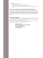
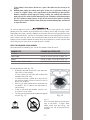
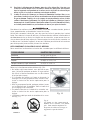
Burner operational notes (g. 10):
• A properly adjusted burner with clean ports will
light within a few seconds.
If using natural gas the ame will be blue with
a deeper blue inner cone.
• If the burner ame is yellow or is noisy the air/
gas mixture maybe incorrect. Contact a service
technician to adjust.
• With LP gas, some yellow tips on the ames are
acceptable. This is normal and adjustment is
not necessary.
• If soot is noticed on pan bottom, contact a ser-
vice technician to adjust.
• The ame should not extend beyond the edge of
the pan (g. 11).
Fig. 10
RIGHT WRONG
Fig. 11
Never extend the flame beyond the outer
edge of the utensil. A higher f
lame
simply wastes heat and energy, and
increases your risk of being bur ned by
the flame.

-18-
MAINTENANCE
CLEANING SAFETY
Turn off all controls and wait for appliance parts to cool before touching or cleaning
them. Do not touch the burner grates or surrounding areas until they have had sufcient
time to cool.
Clean appliance with caution. Use care to avoid steam burns if a wet sponge or cloth
is used to wipe spills on a hot surface. Some cleaners can produce noxious fumes if
applied to a hot surface.
BURNERS
Take off the removable parts and put them for 10 minutes in a soapy warm water. Even-
tual stubborn soils can be removed by using a nonabrasive pad or a plastic scouring
pad.
SURFACE CLEANING
This is easily done using a damp cloth and a non-abrasive detergent, wipe using a soft
dry cloth. For stainless steel parts with stubborn soils, use only plastic scrubbing pad or
a sponge with vinegar and warm water.
Because of many new cleaning products introduced in the marketplace each year, it is
not possible to list all products that can be safety be used to clean this appliance. Read
carefully the cleaner manufacturer’s instructions to be sure the cleaner can be safely
used on this appliance. To determine if a cleaning product is safe, test a small incon-
spicuous area using a very light pressure to see if the surface may scratch or discolour.
This is particularly important for porcelain enamel, highly polished, shiny, painted or
plastic surfaces.
ABNORMAL OPERATION
Any of the following are considered to be abnormal operation and may require servi-
cing:
• Burner ame with yellow tips.
• Soot on pan bottom.
• Difcult burner ignition.
• Burners fail to remain lighted.
• Burner will ame out.
• Difculty in turning gas valves.
NOTES: control regularly the correct functioning of gas valves.
In case of abnormal functioning of these devices, you must immediately call a qualied
technical assistance service.
PROBLEM SOLVER
Before calling for service
• Make sure that the gas shut off valve is in the ON position and the gas supply to
the house in not shut off.
• Make sure the burner caps are properly positioned and the burner ports are not
clogged. Clear ports with a wire if clogged.
• Make sure the igniters are clean and dry.
• Make sure that there is no draft in the room.
• Check the power supply. It should be properly grounded with the correct polarity.
Check that the unit is plugged in and the circuit breaker is not tripped.
• When the electrical power connection has been activated at the rst power up or
reconnected after an outage, the igniters may spark several times even though
all burner knobs are in the off position.
!

-19-
WHAT IS COVERED:
FOSTER guarantees its products for a period of
24 months from the date of original purchase
by nal customer. The purchase must be ve-
ried with a valid receipt issued by the dealer
(receipt, invoice or delivery note) that identies
the purchased product, date of purchase and /
or delivery of the same.
The buyer must report any esthetical defect wi-
thin the rst month of purchase of the product.
The warranty covers manufacturing defects to
all components except for the external piping
and / or any accessories.
WHAT IS NOT COVERED:
• Damage caused during installation of the
product (reversing doors, removing screws or
brackets, adjusting feet, burners, etc.)
• Damage derived from the connection of the
power, gas, water and/or electricity supply.
• Damage to knobs, handles, plastic parts, re-
movable panels, lamps, glass parts and exter-
nal rubber tubes.
• Damaged caused from accident, alteration,
misuse, abuse, re, ood, acts of God, impro-
per installation or use of products not appro-
ved by Foster.
• Damage to external components on which
the consumer may intervene directly during
use and / or maintenance, and which may be
subject to wear.
• The formation of rust and stains on the steel
due to the use of unsuitable cleaning agents.
• Any functional defect indicated by the user
and not conrmed during the process of ve-
rication by the technician. In this case the
intervention fee will be charged in full to the
consumer.
• Any parts that are Damaged from transportation
not carried out by a Foster approved carrier.
• Incorrect installation or maintenance, insuf-
cient or excessive electrical ow, plumbing or
gas abnormalities, insufciency of the chim-
neys, and poor fuel quality.
• Failure to follow the Foster instruction manual.
• Repair by unauthorized personnel.
• This warranty applies to appliances used in
residential application; it does not cover their
use in commercial situations, which are not
allowed for this product.
• Travel fees and associated charges incurred
when the product is installed in a location
with limited or restricted access (i.e., isolated
geographic regions located beyond 50 miles
from the nearest Foster dealer).
• Also not included are service visits to:
a) Educate the customer in the proper use
and care of the product.
b) Correct the installation. The customer is re-
sponsible for providing electrical wiring and/or
gas installation and other connecting facilities.
c) Reset circuit breakers or replace home fuses
Should the appliance be sold by the original
purchaser during the warranty period, the new
owner continues to be protected until the expi-
ration date of the original purchaser’s warranty
period. During the warranty period, FOSTER will
replace, or repair free of charge, all components
that are defective in origin, leaving unchanged
the deadline and the warranty acquired at the
time of purchase. The repair is free of char-
ge provided it is carried out by an authorized
FOSTER Technical Assistance Centre. If the
equipment is repaired at one of the Authorised
Service Centres indicated by the manufacturer
and in the case of replacement of the product,
shipping will be free of charge. In cases whe-
re repair at home is declined, transport to and
from the assistance centre will not be paid for or
provided by FOSTER. Once the warrantee time
has elapsed, the warranty becomes void and as-
sistance will be made by debiting the cost of
the replaced parts, and the costs of labour and
transportation, according to the rates in force.
Authorized technicians will be sent in due time
by FOSTER, with the desire of offering the best
service available. FOSTER is not liable for any
damages, direct or indirect, caused to people,
objects and pets for failure to follow all the in-
structions given in the instruction booklet and
from damages resulting from the forced su-
spension of the use thereof. FOSTER will not
be liable for damages arising from any repairs
made by unqualied staff untrained by the ma-
nufacturer. This warranty applies to appliances
used in residential application; it does not cover
their use in commercial situations.
This warranty is for products purchased and
retained in the 50 states of the U.S.A., the Di-
strict of Columbia and the following provinces
of Canada: Quebec, Ontario, Alberta, and
British Columbia.
FOSTER DOES NOT ASSUME ANY RESPONSILITY
FOR INCIDENTAL OR CONSEQUENTIAL DAMAGES.
Some states do not allow the exclusion or limi-
tation of incidental or consequential damages,
so the above limitation or exclusion may not
apply to you. This warranty gives you specic
legal rights and you may also have other rights
which may vary from state to state or province
to province.
Foster Service Center
7575 E Redield Rd #129, Scottsdale, AZ 85260
Telephone (888) 639-6001
E-mail: [email protected]
Fax: (480)998-7877
GENERAL CONDITIONS OF GUARANTEE

La page est en cours de chargement...
La page est en cours de chargement...
La page est en cours de chargement...
La page est en cours de chargement...
La page est en cours de chargement...
La page est en cours de chargement...
La page est en cours de chargement...
La page est en cours de chargement...
La page est en cours de chargement...
La page est en cours de chargement...
La page est en cours de chargement...
La page est en cours de chargement...
La page est en cours de chargement...
La page est en cours de chargement...
La page est en cours de chargement...
La page est en cours de chargement...
La page est en cours de chargement...
La page est en cours de chargement...
La page est en cours de chargement...
La page est en cours de chargement...
-
 1
1
-
 2
2
-
 3
3
-
 4
4
-
 5
5
-
 6
6
-
 7
7
-
 8
8
-
 9
9
-
 10
10
-
 11
11
-
 12
12
-
 13
13
-
 14
14
-
 15
15
-
 16
16
-
 17
17
-
 18
18
-
 19
19
-
 20
20
-
 21
21
-
 22
22
-
 23
23
-
 24
24
-
 25
25
-
 26
26
-
 27
27
-
 28
28
-
 29
29
-
 30
30
-
 31
31
-
 32
32
-
 33
33
-
 34
34
-
 35
35
-
 36
36
-
 37
37
-
 38
38
-
 39
39
-
 40
40


Foster N7640VNA-B Manuel utilisateur
- Taper
- Manuel utilisateur
- Ce manuel convient également à
dans d''autres langues
- English: Foster N7640VNA-B User manual
Documents connexes
Autres documents
-
Amana AKS3020 Manuel utilisateur
-
Candy CHG93WX/1 Manuel utilisateur
-
Summit GCJ536SS Manuel utilisateur
-
Bertazzoni PROF366QBXT Le manuel du propriétaire
-
Bertazzoni PM363I0X DL 3de7698693d87ce34b0436f43164
-
Bertazzoni PROF305CTXV Guide d'installation
-
-
-