
Operating Instructions
Betriebsanleitung
Mode d'emploi
Manual de Instrucciones
GB
D
F
E
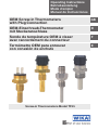
Screw-in Thermometers Model TF35
OEM Screw-in Thermometers
with Plug Connection
OEM-Einschraub-Thermometer
mit Steckeranschluss
Sonde de température OEM à visser
avec raccordement du connecteur
Termómetro OEM para enroscar
con conexión de enchufe

2
11442042.03 02/2010 GB/D/F/E
WIKA Operating Instructions Screw-in Thermometers, Model TF35
GB
D
F
E
Operating Instructions Model TF35 Page 3 - 14
Betriebsanleitung Typ TF35 Seite 15 - 26
Mode d'emploi Type TF35 Page 27 - 38
Manual de Instrucciones Modelo TF35
Página 39 - 50
© WIKA Alexander Wiegand SE & Co. KG 2010
Prior to starting any work, read the operating instructions!
Keep for later use!
Vor Beginn aller Arbeiten Betriebsanleitung lesen!
Zum späteren Gebrauch aufbewahren!
Lire le mode d'emploi avant de commencer toute opération !
A conserver pour une utilisation ultérieure !
¡Leer el manual de instrucciones antes de comenzar cualquier trabajo!
¡Guardar el manual para una eventual consulta posterior!

WIKA Operating Instructions Screw-in Thermometers, Model TF35 3
11442042.03 02/2010 GB/D/F/E
GB
Contents
1. General information 4
2. Safety 5
3. Specications 8
4. Design and function 9
5. Transport, packaging and storage 10
6. Commissioning, operation 11
7. Maintenance and cleaning 12
8. Dismounting, return and disposal 12
Contents

4 WIKA Operating Instructions Screw-in Thermometers, Model TF35
11442042.03 02/2010 GB/D/F/E
GB
1. General information
1. General information
The screw-in thermometer described in the operating instructions has been
designed and manufactured using state-of-the-art technology.
All components are subject to stringent quality and environmental criteria
during production. Our management systems are certied to ISO 9001 and
ISO 14001.
These operating instructions contain important information on handling the
screw-in thermometer. Working safely requires that all safety instructions
and work instructions are observed.
Observe the relevant local accident prevention regulations and general
safety regulations for the screw-in thermometer's range of use.
The operating instructions are part of the instrument and must be kept in the
immediate vicinity of the screw-in thermometer and readily accessible to
skilled personnel at any time.
Skilled personnel must have carefully read and understood the operating
instructions, prior to beginning any work.
The manufacturer's liability is void in the case of any damage caused by
using the product contrary to its intended use, non-compliance with these
operating instructions, assignment of insuciently qualied skilled person-
nel or unauthorised modications to the screw-in thermometer.
The general terms and conditions, contained in the sales documentation,
shall apply.
Subject to technical modications.
Further information:
- Internet address: www.wika.de / www.wika.com
- Relevant data sheet: TE 67.10
- Application consultant: Tel.: (+49) 9372/132-0
Fax: (+49) 9372/132-406
E-Mail: [email protected]

WIKA Operating Instructions Screw-in Thermometers, Model TF35 5
11442042.03 02/2010 GB/D/F/E
GB
1. General information / 2. Safety
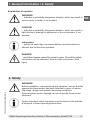
Explanation of symbols
WARNING!
... indicates a potentially dangerous situation, which can result in
serious injury or death, if not avoided.
CAUTION!
... indicates a potentially dangerous situation, which can result in
light injuries or damage to equipment or the environment, if not
avoided.
Information
... points out useful tips, recommendations and information for
ecient and trouble-free operation.
DANGER!
...identies hazards caused by electric power. Should the safety
instructions not be observed, there is a risk of serious or fatal
injury.
2. Safety
WARNING!
Before installation, commissioning and operation, ensure that the
appropriate thermometer has been selected in terms of measu-
ring range, design and specic measuring conditions.
Serious injuries and/or damage can occur should these not be
observed.
Further important safety instructions can be found in the individu-
al chapters of these operating instructions.

6 WIKA Operating Instructions Screw-in Thermometers, Model TF35
11442042.03 02/2010 GB/D/F/E
GB
2. Safety
2.1 Intended use
The Model TF35 screw-in thermometer with plug connection is designed for
temperature measurement.
The screw-in thermometer has been designed and built solely for the intended
use described here, and may only be used accordingly.
The technical specications contained in these operating instructions must be
observed. Should the instrument be improperly handled or operated outside
of its technical specications, it has to be taken out of service immediately and
inspected by an authorised WIKA service engineer.
The manufacturer shall not be liable for claims of any type based on operation
contrary to the intended use.
2.2 Personnel qualication
WARNING!
Risk of injury should qualication be insucient!
Improper handling can result in considerable injury and damage
to equipment.
The activities described in these operating instructions
may only be carried out by skilled personnel who have the
qualications described below.
Keep unqualied personnel away from hazardous areas.
Skilled personnel
Skilled personnel are understood to be personnel who, based on their techni-
cal training, knowledge of measurement and control technology and on their
experience and knowledge of country-specic regulations, current standards
and directives, are capable of carrying out the work described and indepen-
dently recognising potential hazards.
Special operating conditions require further appropriate knowledge, e.g. of
aggressive media.

WIKA Operating Instructions Screw-in Thermometers, Model TF35 7
11442042.03 02/2010 GB/D/F/E
GB
2. Safety
2.3 Special hazards
WARNING!
For hazardous media such as oxygen, acetylene, ammable or
toxic gases or liquids, and refrigeration plants, compressors,
etc., in addition to all standard regulations, the appropriate
existing codes or regulations must also be followed.
WARNING!
Protection from electrostatic discharge (ESD) required.
The proper use of grounded work surfaces and personal wrist
straps is required when working with exposed circuitry (printed
circuit boards), in order to to prevent static discharge from
damaging sensitive electronic components.
To ensure safe working on the instrument, the operating compa-
ny must ensure
that suitable rst-aid equipment is available and aid is
provided whenever required.
that the operating personnel are regularly instructed in all
topics regarding work safety, rst aid and environmental
protection and knows the operating instructions and, in parti-
cular, the safety instructions contained therein.
DANGER!
Danger of death caused by electric current
Upon contact with live parts, there is a direct danger of death.
Electrical instruments may only be installed and mounted by
skilled electrical personnel.
Operation using a defective power supply unit (e.g. short
circuit from the mains voltage to the output voltage) may result
in life-threatening voltages at the screw-in thermometer!
WARNING!
Residual media in dismounted instruments can result in a risk
to persons, the environment and the equipment. Take sucient
precautionary measures.

8 WIKA Operating Instructions Screw-in Thermometers, Model TF35
11442042.03 02/2010 GB/D/F/E
GB
2. Safety / 3. Specications
Do not use this screw-in thermometer in safety or Emergency
Stop devices. Incorrect use of the screw-in thermometer can
result in injury.
Should a failure occur, aggressive media with extremely high
temperature and under high pressure or vacuum may be present
at the screw-in thermometer.
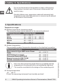
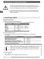
3. Specications
Temperature ranges
Medium temperature (measuring range)
The measuring range mainly depends on the measuring element:
Measuring element Measuring range
NTC -40 ... +130 °C
Pt100 -50 ... +200 °C / -50 ... +300 °C
Pt1000 -50 ... +200 °C / -50 ... +300 °C
Ni1000 -50 ... +200 °C
KTY -50 ... +150 °C
Ambient temperature
The permissible ambient temperature depends on the electrical connection:
Electrical connection Ambient temperature
Plug connector type AMP Junior Power
Timer
-40 ... +150 °C
FASTON blade terminals -40 ... +150 °C
Connector Deutsch DT04-2P -40 ... +150 °C
Bayonet connector DIN 72 585 -40 ... +140 °C
Circular connector M12 x 1 -40 ... +100 °C
Due to its short immersion length there is a possibility that the
temperature at the plug will rise to an inadmissibly high level.
This must be considered in the design of the measuring point.
Storage temperature
-40 … +85 °C
Protect the measuring instrument from humidity and dust!

WIKA Operating Instructions Screw-in Thermometers, Model TF35 9
11442042.03 02/2010 GB/D/F/E
GB
3. Specications / 4. Design and function
Vibration resistance
Depending on the installation situation, medium, temperature and insertion
length vibration resistance in accordance with DIN EN 60 751, can be as high as
10 g.
Shock resistance
up to 500 g, depending on installation situation, medium and temperature
Working pressure
max. 600 bar, depending on medium, temperature and thermowell design
Electrical connection
Plug, AMP Junior Power Timer
FASTON blade terminal 6.3 x 0.8 mm
FASTON blade terminal 4.8 x 0.8 mm
Circular connector, M12 x 1
Connector, Deutsch DT04-2P
Bayonet connector, DIN 72 585
Ingress protection
IP 66 / IP 67 once connected (provided installation has been carried out in the
correct manner)
For further specications see WIKA Data Sheet TE 67.10 and the order
documentation.
4. Design and function
4.1 Description
The Model TF35 screw-in thermometer consists of a thermowell with integrated
measuring element and a built-in connector. The screw-in thermometer can be
screwed in directly into the process.
Each electrical component is protected against splash water.
Electrical connection is made via the connector.
The Model TF35 screw-in thermometer has a high shock- and vibration-
resistance. The vibration resistance of the standard version is up to 10 g. The
shock resistance exceeds the requirements of DIN EN 60 751.
4.2 Scope of delivery
Cross-check scope of delivery with delivery note.

10 WIKA Operating Instructions Screw-in Thermometers, Model TF35
11442042.03 02/2010 GB/D/F/E
GB
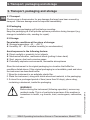
5. Transport, packaging and storage
5. Transport, packaging and storage
5.1 Transport
Check screw-in thermometer for any damage that may have been caused by
transport. Obvious damage must be reported immediately.
5.2 Packaging
Do not remove packaging until just before mounting.
Keep the packaging as it will provide optimum protection during transport (e.g.
change in installation site, sending for repair).
5.3 Storage
Permissible conditions at the place of storage:
Storage temperature: -40 ... +85 °C
Humidity: 35 ... 85 % relative humidity (no condensation)
Avoid exposure to the following factors:
Direct sunlight or proximity to hot objects
Mechanical vibration, mechanical shock (putting it down hard)
Soot, vapour, dust and corrosive gases
Potentially explosive environments, ammable atmospheres
Store the instrument in its original packaging in a location that fulls the
conditions listed above. If the original packaging is not available, pack and store
the instrument as described below:
1. Wrap the instrument in an antistatic plastic lm.
2. Place the instrument, along with shock-absorbent material, in the packaging.
3. If stored for a prolonged period of time (more than 30 days), place a bag,
containing a desiccant, inside the packaging.
WARNING!
Before storing the instrument (following operation), remove any
residual media. This is of particular importance if the medium is
hazardous to health, e.g. caustic, toxic, carcinogenic, radioactive,
etc.

WIKA Operating Instructions Screw-in Thermometers, Model TF35 11
11442042.03 02/2010 GB/D/F/E
GB
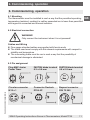
6. Commissioning, operation
6. Commissioning, operation
6.1 Mounting
The thermometer must be installed in such a way that the permitted operating
temperature (ambient, medium) is neither exceeded nor is lower than permitted
with regard to convected and thermal radiation.
6.2 Electrical connection
WARNING!
Only connect the instrument when it is not powered!
Cables and Wiring
Fine gauge stranded cables are supplied with ferrule-ends
The cable used must comply with the relevant requirements with respect to
stability and temperature
The connecting cable must be run in such a way that the possibility of
mechanical damage is eliminated
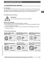
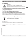
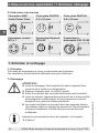
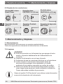
6.3 Pin assignment
Plug AMP Junior
Power Timer
FASTON blade terminal
6.3 x 0.8 mm
FASTON blade terminal
4.8 x 0.8 mm
Circular connector
M12 x 1
Connector Deutsch
DT04-2P
Bayonet connector
DIN 72 585

12 WIKA Operating Instructions Screw-in Thermometers, Model TF35
11442042.03 02/2010 GB/D/F/E
GB
7. Maintenance, cleaning / 8. Dismounting, return, ...
7. Maintenance and cleaning
7.1 Maintenance
This screw-in thermometer is maintenance-free.
Repairs must only be carried out by the manufacturer.
7.2 Cleaning
CAUTION!
Before cleaning, switch o the instrument and disconnect it
correctly from the power supply.
Clean the instrument with a moist cloth.
Electrical connections must not come into contact with
moisture.
Wash or clean the dismounted instrument before returning it,
in order to protect sta and the environment from exposure to
residual media.
Residual media in dismounted instruments can result in a risk
to persons, the environment and equipment.
Take sucient precautionary measures.
For information on returning the instrument see chapter "8.2
Return".
8. Dismounting, return and disposal
WARNING!
Residual media in dismounted instruments can result in a risk to
persons, the environment and equipment.
Take sucient precautionary measures.
8.1 Dismounting
WARNING!
Risk of burns!
Let the instrument cool down suciently before dismounting it!
When dismounting it, there is a risk that dangerously hot
pressure media may escape.
Only disconnect the screw-in thermometer once the system has been depres-
surised!

WIKA Operating Instructions Screw-in Thermometers, Model TF35 13
11442042.03 02/2010 GB/D/F/E
GB
8. Dismounting, return and disposal
8.2 Return
WARNING!
Strictly observe when shipping the instrument:
All instruments delivered to WIKA must be free from any kind of
hazardous substances (acids, bases, solutions, etc.).
When returning the instrument, use the original packaging or a suitable
transport package.
To avoid damage:
1. Wrap the instrument in an antistatic plastic lm.
2. Place the instrument, along with the shock-absorbent material, in the
packaging.
Place shock-absorbent material evenly on all sides of the shipping box.
3. If possible, place a bag, containing a desiccant, inside the packaging.
4. Label the shipment as transport of a highly sensitive measuring instrument.
Enclose the completed return form with the instrument.
The return form is available on the internet:
www.wika.de / Service / Return
8.3 Disposal
Incorrect disposal can put the environment at risk.
Dispose of instrument components and packaging materials in an environ-
mentally compatible way and in accordance with the country-specic waste
disposal regulations.

14 WIKA Operating Instructions Screw-in Thermometers, Model TF35
11442042.03 02/2010 GB/D/F/E
GB

WIKA Betriebsanleitung Einschraub-Thermometer, Typ TF35 15
D
11442042.03 02/2010 GB/D/F/E
Inhalt
1. Allgemeines 16
2. Sicherheit 17
3. Technische Daten 20
4. Aufbau und Funktion 21
5. Transport, Verpackung und Lagerung 22
6. Inbetriebnahme, Betrieb 23
7. Wartung und Reinigung 24
8. Demontage, Rücksendung und Entsorgung 24
Inhalt

WIKA Betriebsanleitung Einschraub-Thermometer, Typ TF3516
D
11442042.03 02/2010 GB/D/F/E
1. Allgemeines
1. Allgemeines
Das in der Betriebsanleitung beschriebene Einschraub-Thermometer wird
nach den neuesten Erkenntnissen konstruiert und gefertigt.
Alle Komponenten unterliegen während der Fertigung strengen Qualitäts-
und Umweltkriterien. Unsere Managementsysteme sind nach ISO 9001 und
ISO 14001 zertiziert.
Diese Betriebsanleitung gibt wichtige Hinweise zum Umgang mit dem
Einschraub-Thermometer. Voraussetzung für sicheres Arbeiten ist die
Einhaltung aller angegebenen Sicherheitshinweise und Handlungsan-
weisungen.
Die für den Einsatzbereich des Einschraub-Thermometers geltenden
örtlichen Unfallverhütungsvorschriften und allgemeinen Sicherheitsbestim-
mungen einhalten.
Die Betriebsanleitung ist Produktbestandteil und muss in unmittelbarer Nähe
des Einschraub-Thermometers für das Fachpersonal jederzeit zugänglich
aufbewahrt werden.
Das Fachpersonal muss die Betriebsanleitung vor Beginn aller Arbeiten
sorgfältig durchgelesen und verstanden haben.
Die Haftung des Herstellers erlischt bei Schäden durch bestimmungswidrige
Verwendung, Nichtbeachten dieser Betriebsanleitung, Einsatz ungenü-
gend qualizierten Fachpersonals sowie eigenmächtiger Veränderung am
Einschraub-Thermometer.
Es gelten die allgemeinen Geschäftsbedingungen in den Verkaufsunter-
lagen.
Technische Änderungen vorbehalten.
Weitere Informationen:
- Internet-Adresse: www.wika.de / www.wika.com
- zugehöriges Datenblatt: TE 67.10
- Anwendungsberater: Tel.: (+49) 9372/132-0
Fax: (+49) 9372/132-406
E-Mail: [email protected]

WIKA Betriebsanleitung Einschraub-Thermometer, Typ TF35 17
D
11442042.03 02/2010 GB/D/F/E
1. Allgemeines / 2. Sicherheit
Symbolerklärung
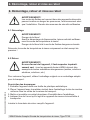
WARNUNG!
… weist auf eine möglicherweise gefährliche Situation hin, die
zum Tod oder zu schweren Verletzungen führen kann, wenn sie
nicht gemieden wird.
VORSICHT!
… weist auf eine möglicherweise gefährliche Situation hin, die
zu geringfügigen oder leichten Verletzungen bzw. Sach- und
Umweltschäden führen kann, wenn sie nicht gemieden wird.
Information
… hebt nützliche Tipps und Empfehlungen sowie Informationen
für einen ezienten und störungsfreien Betrieb hervor.
GEFAHR!
…kennzeichnet Gefährdungen durch elektrischen Strom. Bei
Nichtbeachtung der Sicherheitshinweise besteht die Gefahr
schwerer oder tödlicher Verletzungen.
2. Sicherheit
WARNUNG!
Vor Montage, Inbetriebnahme und Betrieb sicherstellen, dass
das richtige Thermometer hinsichtlich Messbereich, Ausführung
und spezischen Messbedingungen ausgewählt wurde.
Bei Nichtbeachten können schwere Körperverletzungen und/
oder Sachschäden auftreten.
Weitere wichtige Sicherheitshinweise benden sich in den
einzelnen Kapiteln dieser Betriebsanleitung.

WIKA Betriebsanleitung Einschraub-Thermometer, Typ TF3518
D
11442042.03 02/2010 GB/D/F/E
2. Sicherheit
2.1 Bestimmungsgemäße Verwendung
Das Einschraub-Thermometer mit Steckeranschluss Typ TF35 dient zur
Temperaturmessung.
Das Einschraub-Thermometer ist ausschließlich für den hier beschriebenen
bestimmungsgemäßen Verwendungszweck konzipiert und konstruiert und darf
nur dementsprechend verwendet werden.
Die technischen Spezikationen in dieser Betriebsanleitung sind einzuhalten.
Eine unsachgemäße Handhabung oder ein Betreiben des Einschraub-Thermo
-
meters außerhalb der technischen Spezikationen macht die sofortige Stilllegung
und Überprüfung durch einen autorisierten WIKA-Servicemitarbeiter erforderlich.
Ansprüche jeglicher Art aufgrund von nicht bestimmungsgemäßer Verwendung
sind ausgeschlossen.
2.2 Personalqualikation
WARNUNG!
Verletzungsgefahr bei unzureichender Qualikation!
Unsachgemäßer Umgang kann zu erheblichen Personen- und
Sachschäden führen.
Die in dieser Betriebsanleitung beschriebenen Tätigkeiten nur
durch Fachpersonal nachfolgend beschriebener Qualikation
durchführen lassen.
Unqualiziertes Personal von den Gefahrenbereichen fernhal-
ten.
Fachpersonal
Das Fachpersonal ist aufgrund seiner fachlichen Ausbildung, seiner Kenntnisse
der Mess- und Regelungstechnik und seiner Erfahrungen sowie Kenntnis der
landesspezischen Vorschriften, geltenden Normen und Richtlinien in der
Lage, die beschriebenen Arbeiten auszuführen und mögliche Gefahren selbst-
ständig zu erkennen.
Spezielle Einsatzbedingungen verlangen weiteres entsprechendes Wissen,
z. B. über agressive Medien.

WIKA Betriebsanleitung Einschraub-Thermometer, Typ TF35 19
D
11442042.03 02/2010 GB/D/F/E
2. Sicherheit
2.3 Besondere Gefahren
WARNUNG!
Bei gefährlichen Messstoen wie z. B. Sauersto, Acetylen,
brennbaren oder giftigen Stoen, sowie bei Kälteanlagen,
Kompressoren etc. müssen über die gesamten allgemeinen
Regeln hinaus die einschlägigen Vorschriften beachtet werden.
WARNUNG!
Schutz vor elektrostatischer Entladung (ESD) erforderlich!
Die ordnungsgemäße Verwendung geerdeter Arbeitsächen und
persönlicher Armbänder ist bei Arbeiten mit oenen Schaltkrei-
sen (Leiterplatten) erforderlich, um die Beschädigung empnd-
licher elektronischer Bauteile durch elektrostatische Entladung
zu vermeiden.
Für ein sicheres Arbeiten am Gerät muss der Betreiber sicherstellen,
dass eine entsprechende Erste-Hilfe-Ausrüstung vorhanden
ist und bei Bedarf jederzeit Hilfe zur Stelle ist.
dass das Bedienpersonal regelmäßig in allen zutreenden
Fragen von Arbeitssicherheit, Erste-Hilfe und Umweltschutz
unterwiesen wird, sowie die Betriebsanleitung und insbeson-
dere die darin enthaltenen Sicherheitshinweise kennt.
GEFAHR!
Lebensgefahr durch elektrischen Strom
Bei Berührung mit spannungsführenden Teilen besteht unmittel-
bare Lebensgefahr.
Einbau und Montage des elektrischen Gerätes dürfen nur
durch das Elektrofachpersonal erfolgen.
Bei Betrieb mit einem defekten Netzgerät (z. B. Kurzschluss
von Netzspannung zur Ausgangsspannung) können am
Einschraub-Thermometer lebensgefährliche Spannungen
auftreten!
WARNUNG!
Messstoreste in ausgebauten Geräten können zur Gefährdung
von Personen, Umwelt und Einrichtung führen.
Ausreichende Vorsichtsmaßnahmen ergreifen.

WIKA Betriebsanleitung Einschraub-Thermometer, Typ TF3520
D
11442042.03 02/2010 GB/D/F/E
2. Sicherheit / 3. Technische Daten
Dieses Einschraub-Thermometer nicht in Sicherheits- oder in
Not-Aus-Einrichtungen benutzen. Fehlerhafte Anwendungen des
Einschraub-Thermometers können zu Verletzungen führen.
Am Einschraub-Thermometer können im Fehlerfall aggressive
Medien mit extremer Temperatur und unter hohem Druck oder
Vakuum anliegen.
3. Technische Daten
Temperaturbereiche
Mediumstemperatur (Messbereich)
Der Messbereich hängt im Wesentlichen vom Messelement ab:
Messelement Messbereich
NTC -40 ... +130 °C
Pt100 -50 ... +200 °C / -50 ... +300 °C
Pt1000 -50 ... +200 °C / -50 ... +300 °C
Ni1000 -50 ... +200 °C
KTY -50 ... +150 °C
Umgebungstemperatur
Die zulässige Umgebungstemperatur ist abhängig vom elektrischen
Anschluss:
Elektrischer Anschluss Umgebungstemperatur
AMP Junior Power Timer -40 ... +150 °C
FASTON-Flachstecker -40 ... +150 °C
Gerätestecker Deutsch DT04-2P -40 ... +150 °C
Bajonett-Steckverbinder DIN 72 585 -40 ... +140 °C
Rundsteckverbinder M12 x 1 -40 ... +100 °C
Aufgrund der kurzen Baulänge besteht die Möglichkeit, dass die
Temperatur am Stecker auf unzulässig hohe Werte steigt. Dies
muss bei der Ausführung der Messstelle unbedingt berücksich-
tigt werden.
Lagertemperatur
-40 … +85 °C
Messgeräte vor Feuchtigkeit und Staub schützen!
La page est en cours de chargement...
La page est en cours de chargement...
La page est en cours de chargement...
La page est en cours de chargement...
La page est en cours de chargement...
La page est en cours de chargement...
La page est en cours de chargement...
La page est en cours de chargement...
La page est en cours de chargement...
La page est en cours de chargement...
La page est en cours de chargement...
La page est en cours de chargement...
La page est en cours de chargement...
La page est en cours de chargement...
La page est en cours de chargement...
La page est en cours de chargement...
La page est en cours de chargement...
La page est en cours de chargement...
La page est en cours de chargement...
La page est en cours de chargement...
La page est en cours de chargement...
La page est en cours de chargement...
La page est en cours de chargement...
La page est en cours de chargement...
La page est en cours de chargement...
La page est en cours de chargement...
La page est en cours de chargement...
La page est en cours de chargement...
La page est en cours de chargement...
La page est en cours de chargement...
La page est en cours de chargement...
La page est en cours de chargement...
-
 1
1
-
 2
2
-
 3
3
-
 4
4
-
 5
5
-
 6
6
-
 7
7
-
 8
8
-
 9
9
-
 10
10
-
 11
11
-
 12
12
-
 13
13
-
 14
14
-
 15
15
-
 16
16
-
 17
17
-
 18
18
-
 19
19
-
 20
20
-
 21
21
-
 22
22
-
 23
23
-
 24
24
-
 25
25
-
 26
26
-
 27
27
-
 28
28
-
 29
29
-
 30
30
-
 31
31
-
 32
32
-
 33
33
-
 34
34
-
 35
35
-
 36
36
-
 37
37
-
 38
38
-
 39
39
-
 40
40
-
 41
41
-
 42
42
-
 43
43
-
 44
44
-
 45
45
-
 46
46
-
 47
47
-
 48
48
-
 49
49
-
 50
50
-
 51
51
-
 52
52


dans d''autres langues
- español: WIKA TF35 Instrucciones de operación
- Deutsch: WIKA TF35 Bedienungsanleitung